 |
Eastern Sierra Nevada Power Plant Construction California Electric Power Corporation Nevada Power, Milling, & Mining Co. Southern Sierras Power Company |
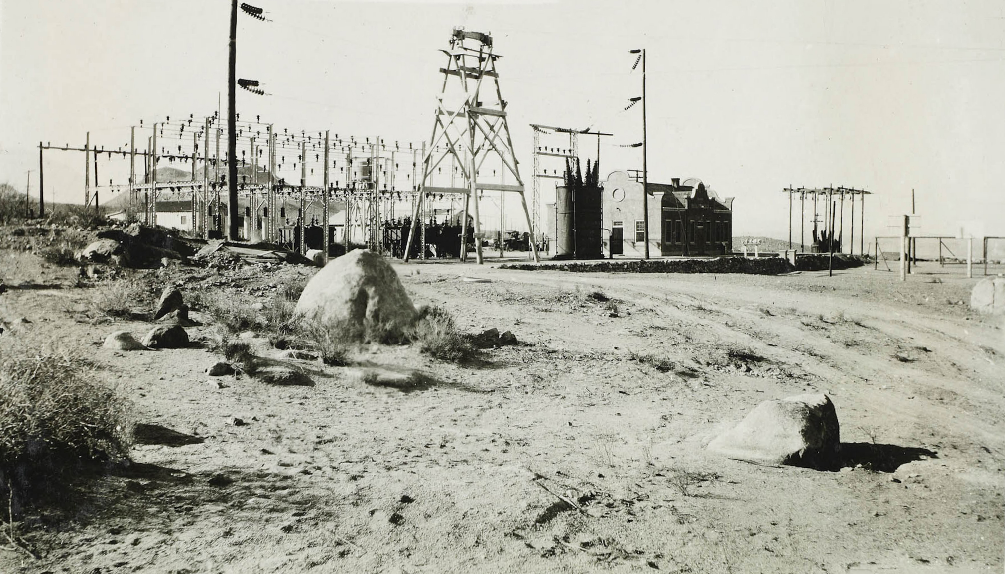
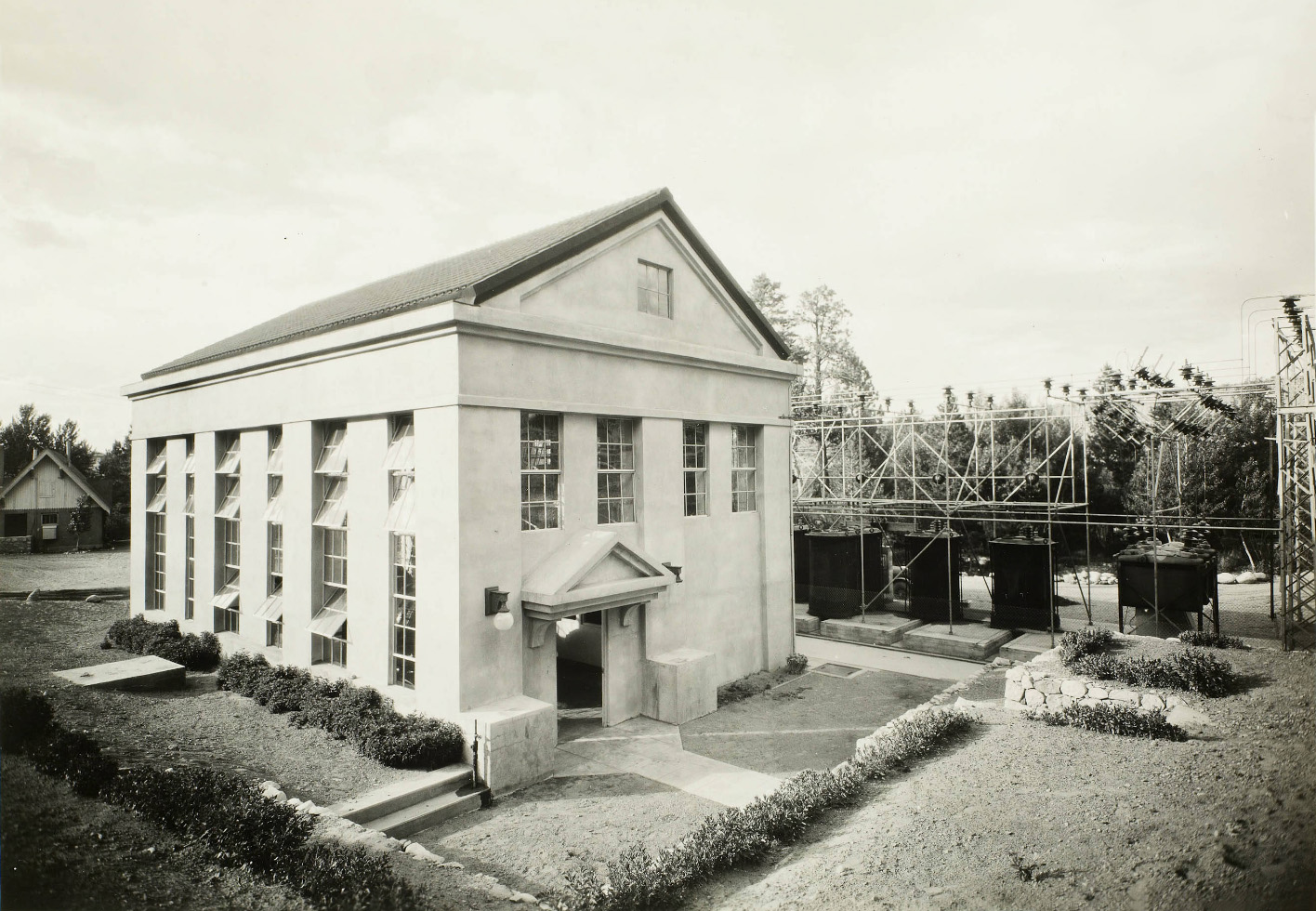
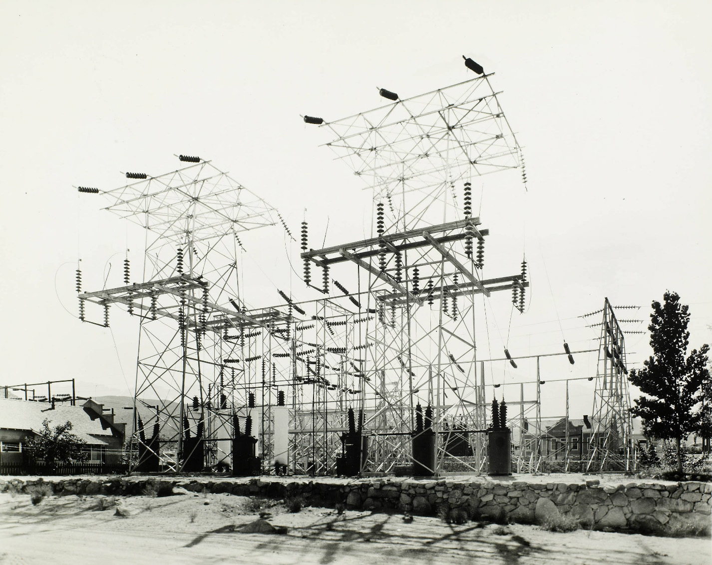
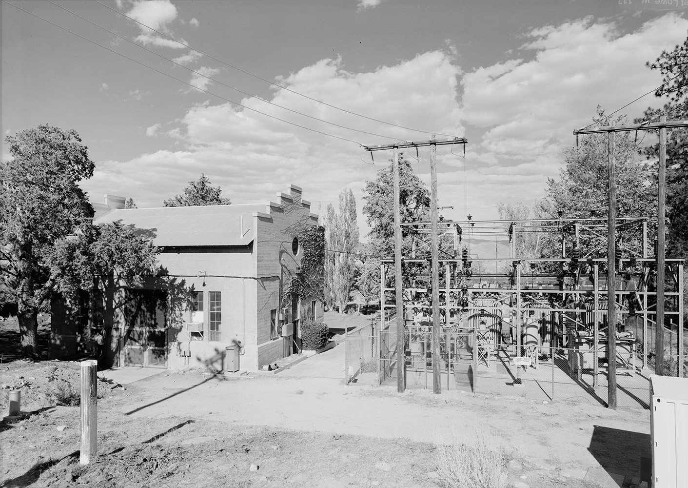
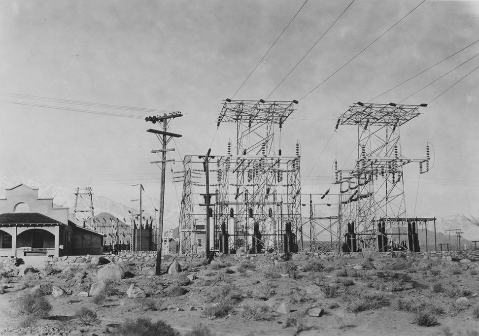
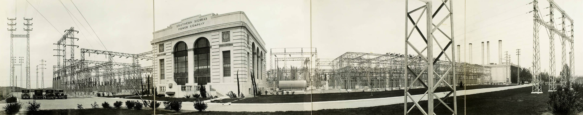 Main Substation of the Southern Sierras Power Company - San Bernardino, CA This is the southern terminus of the 238 mile steel tower transmission line from the Control Station on Bishop Creek. Here current is received from four sources for distribution - from the eleven hydro plants in the North; from the San Bernardino steam-electric generating plant, from the interconnections with the Southern California Edison Company's system, and from the San Diego Consolidated Gas and Electric Company through the Rincon interconnection. Power is distributed here to all points on the System in Southern California and for resale in Arizona and Lower California. This statioin was completed in 1927 |
|
All photos and text are from The Huntington Digital Library unless otherwise noted |

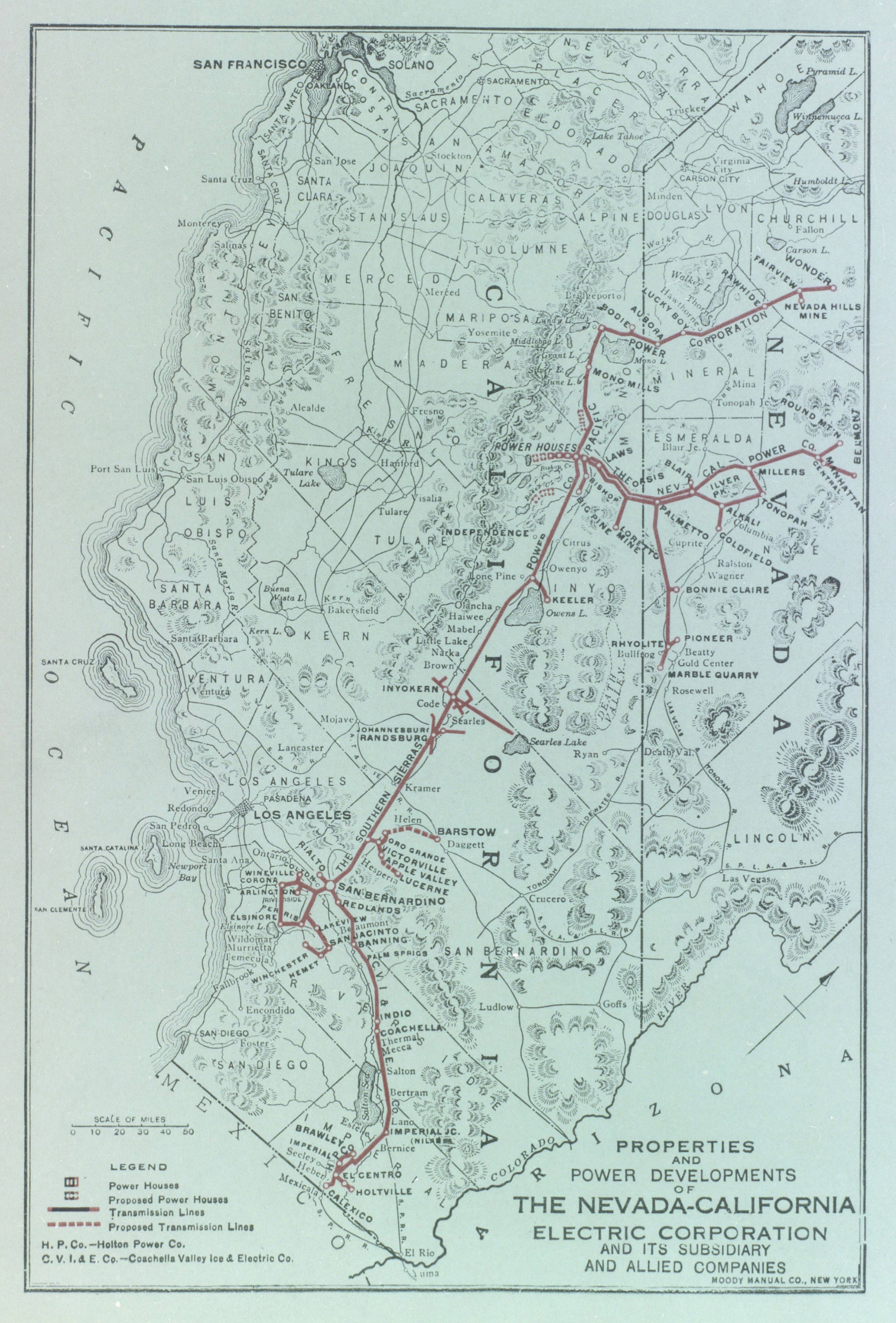
Nevada-California Electric Corporation Power Development Map
Power House Locations |
|
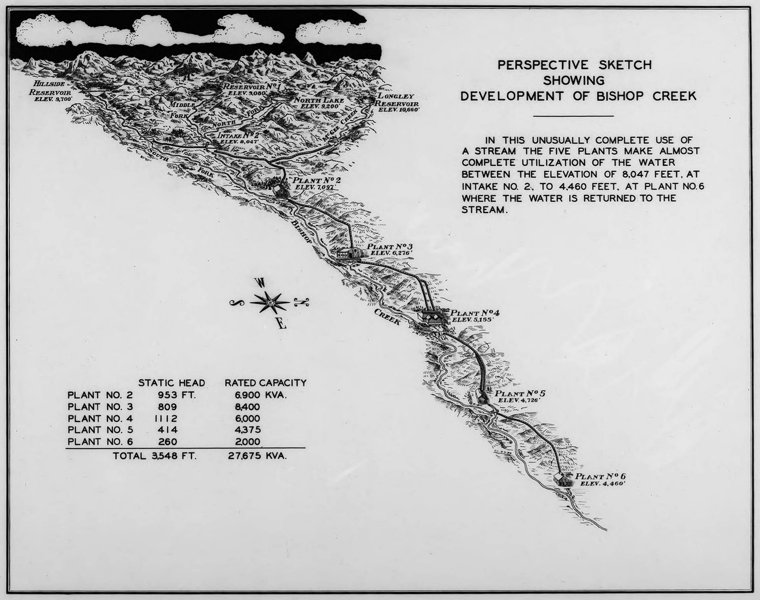 Bishop Creek - Power House No. 2, 3, 4, 5, 6 |
|
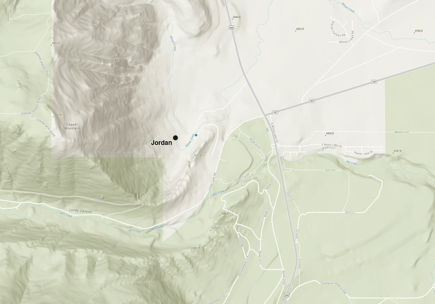 Jordan Powerhouse (Map courtesy of U.S. Energy Information Administration) |
|
 Lundy (Mill Creek) and Poole Powerhouses (Map courtesy of U.S. Energy Information Administration) |
 Rush Creek Powerhouse (Map courtesy of U.S. Energy Information Administration) |
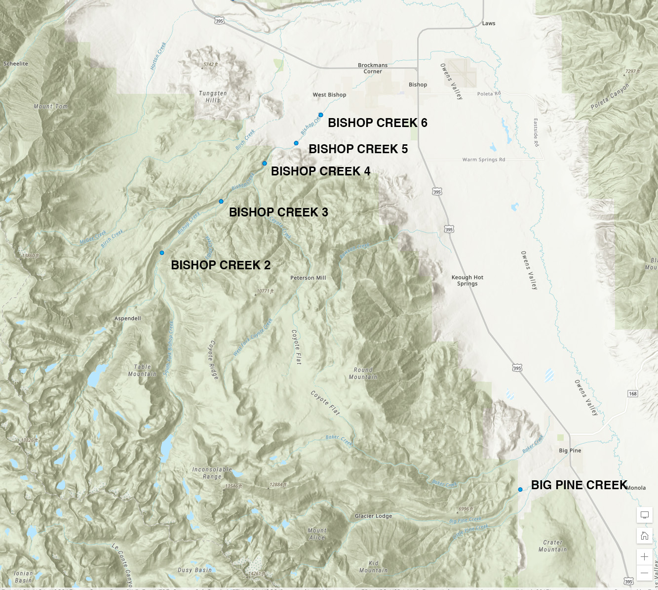 Bishop Creek - Powerhouse No. 2, 3, 4, 5, 6 and Big Pine Creek (Map courtesy of U.S. Energy Information Administration) |
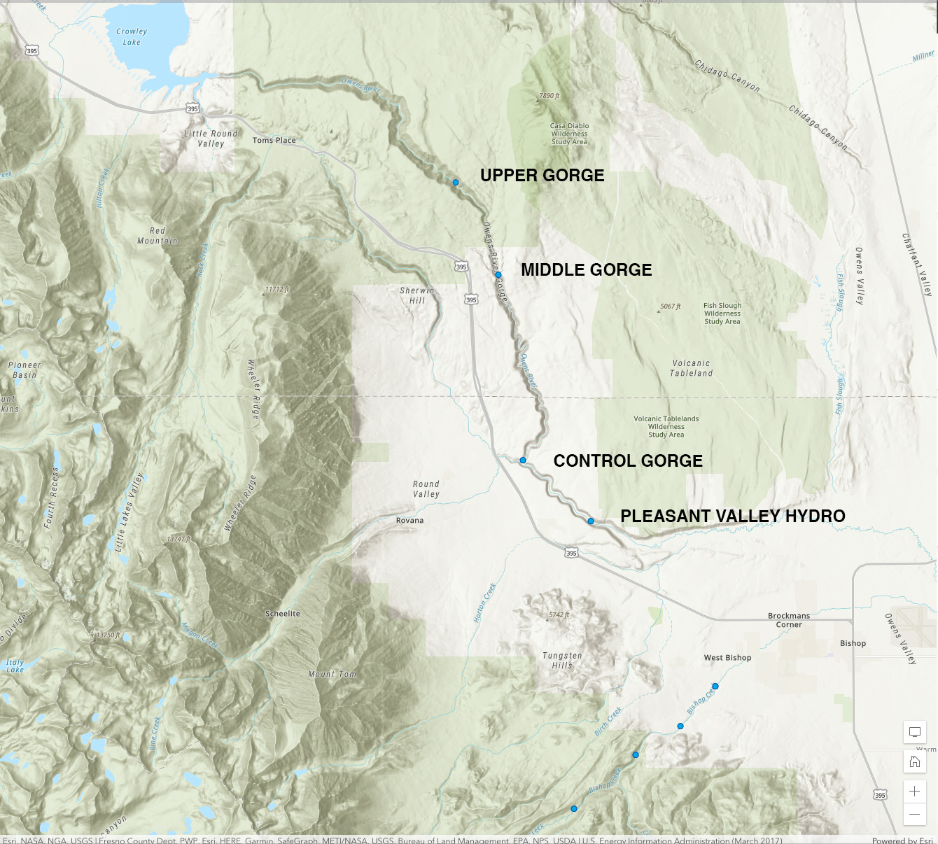 Owens River Gorge Powerhouses and Pleasant Valley (Map courtesy of U.S. Energy Information Administration) |
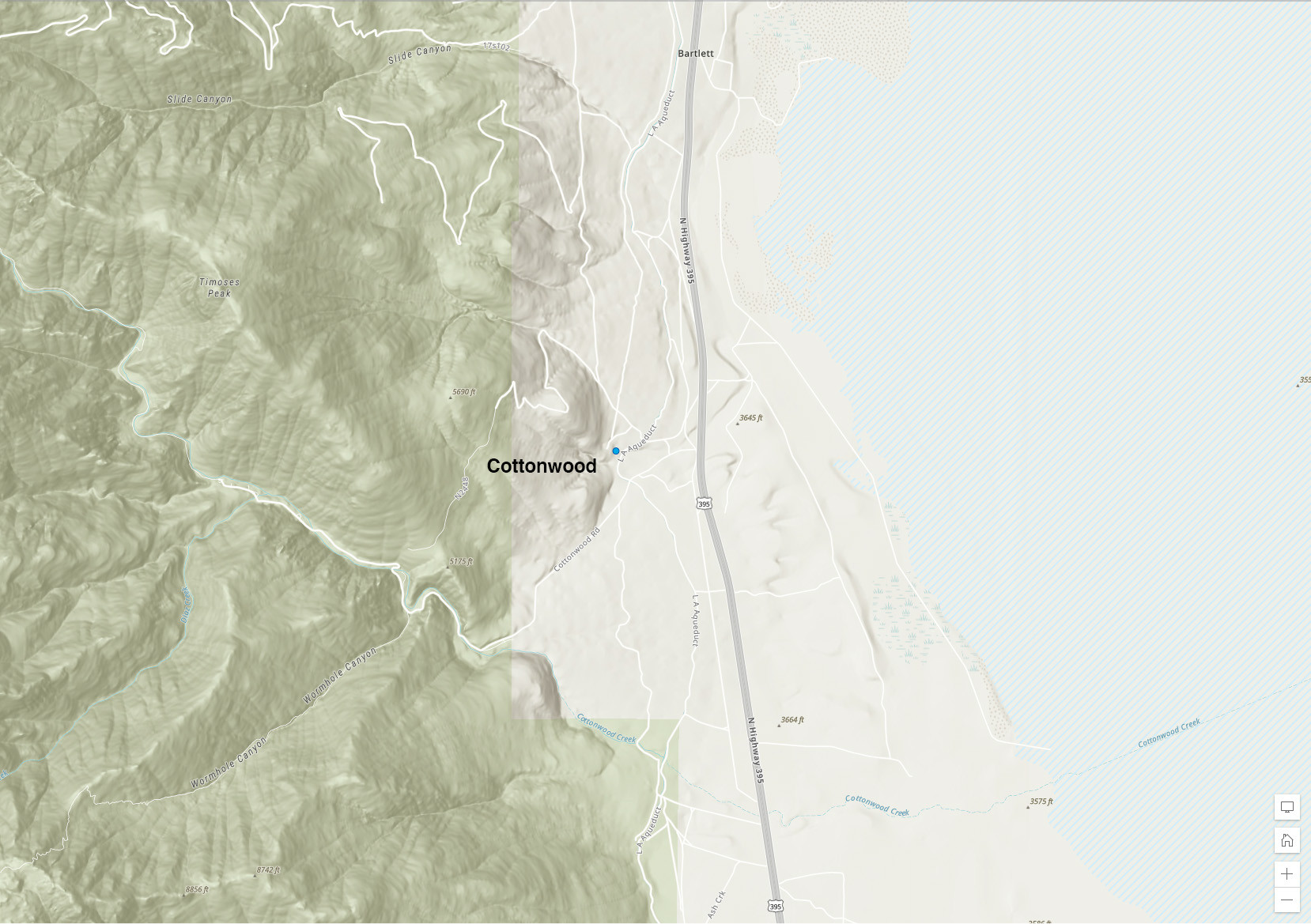 Cottonwood Powerhouse (Map courtesy of U.S. Energy Information Administration) |
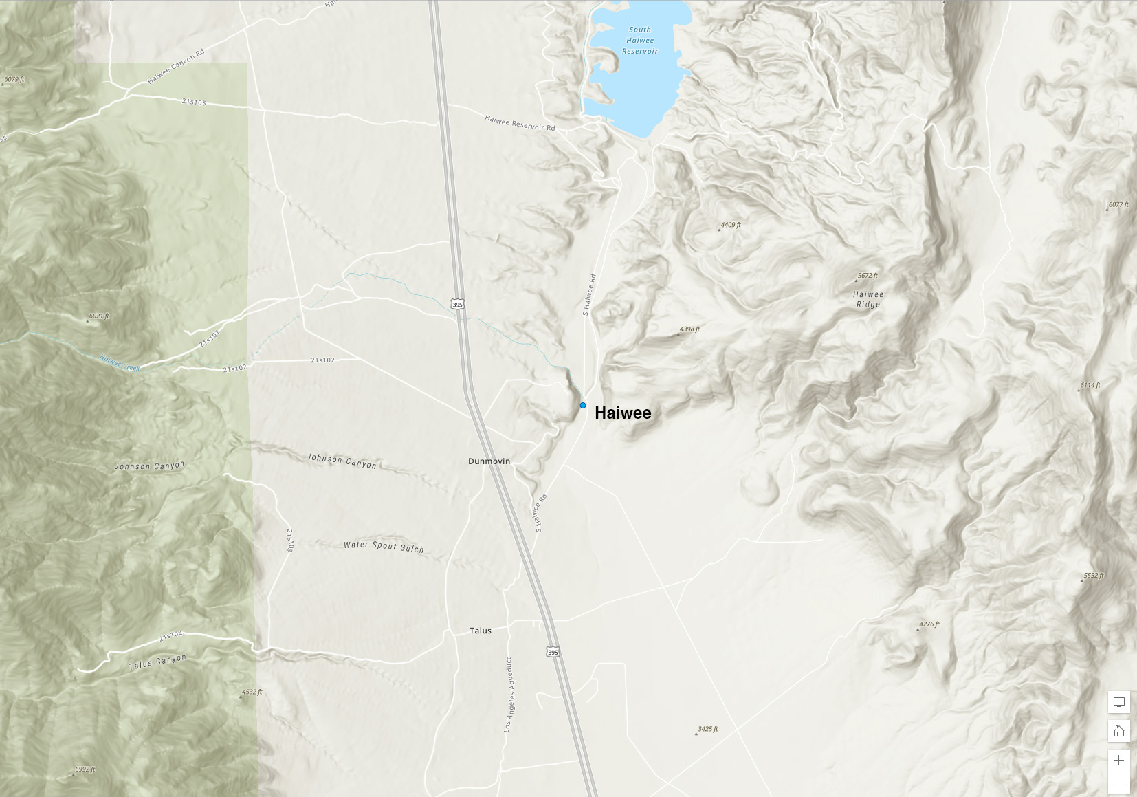 Haiwee Powerhouse (Map courtesy of U.S. Energy Information Administration) |
Hydroelectric Power Developments in Southern California
by Robert Charles Catren
(Photo courtesy of Rick Olson)
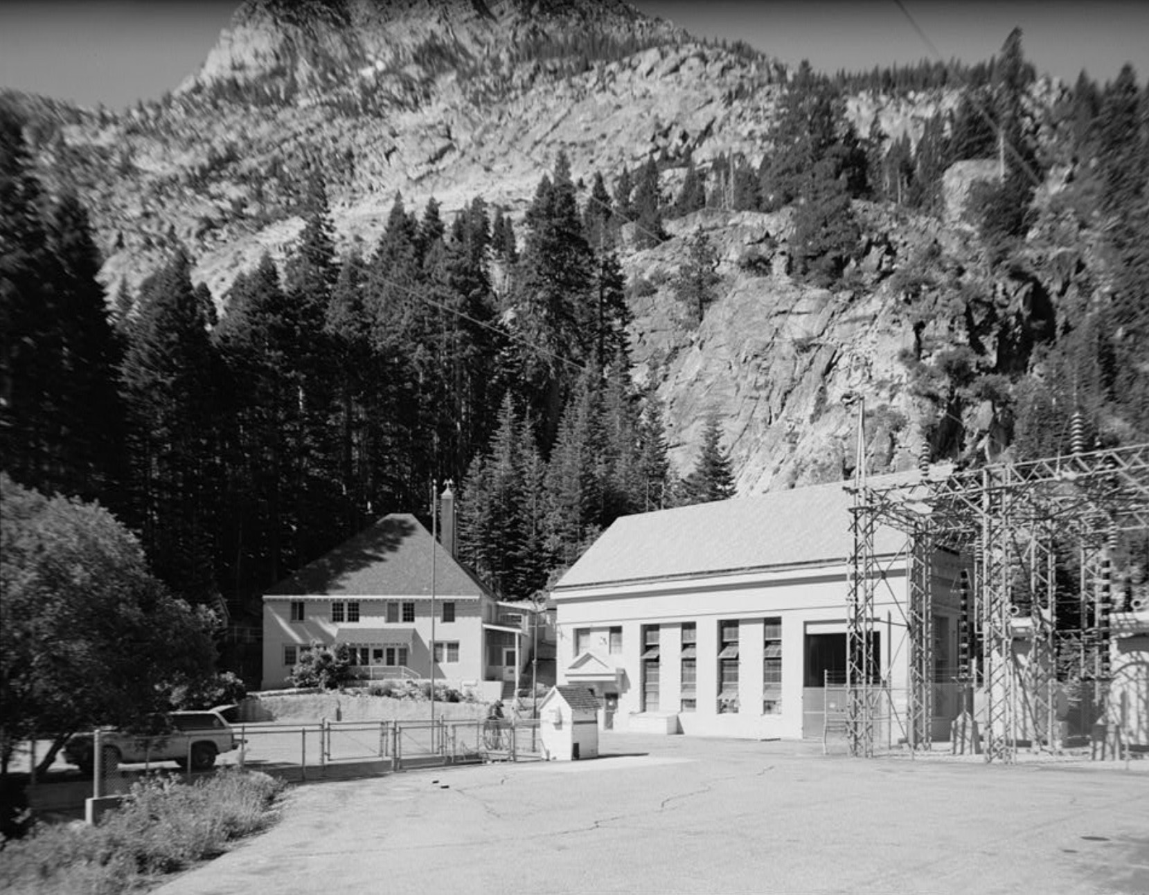
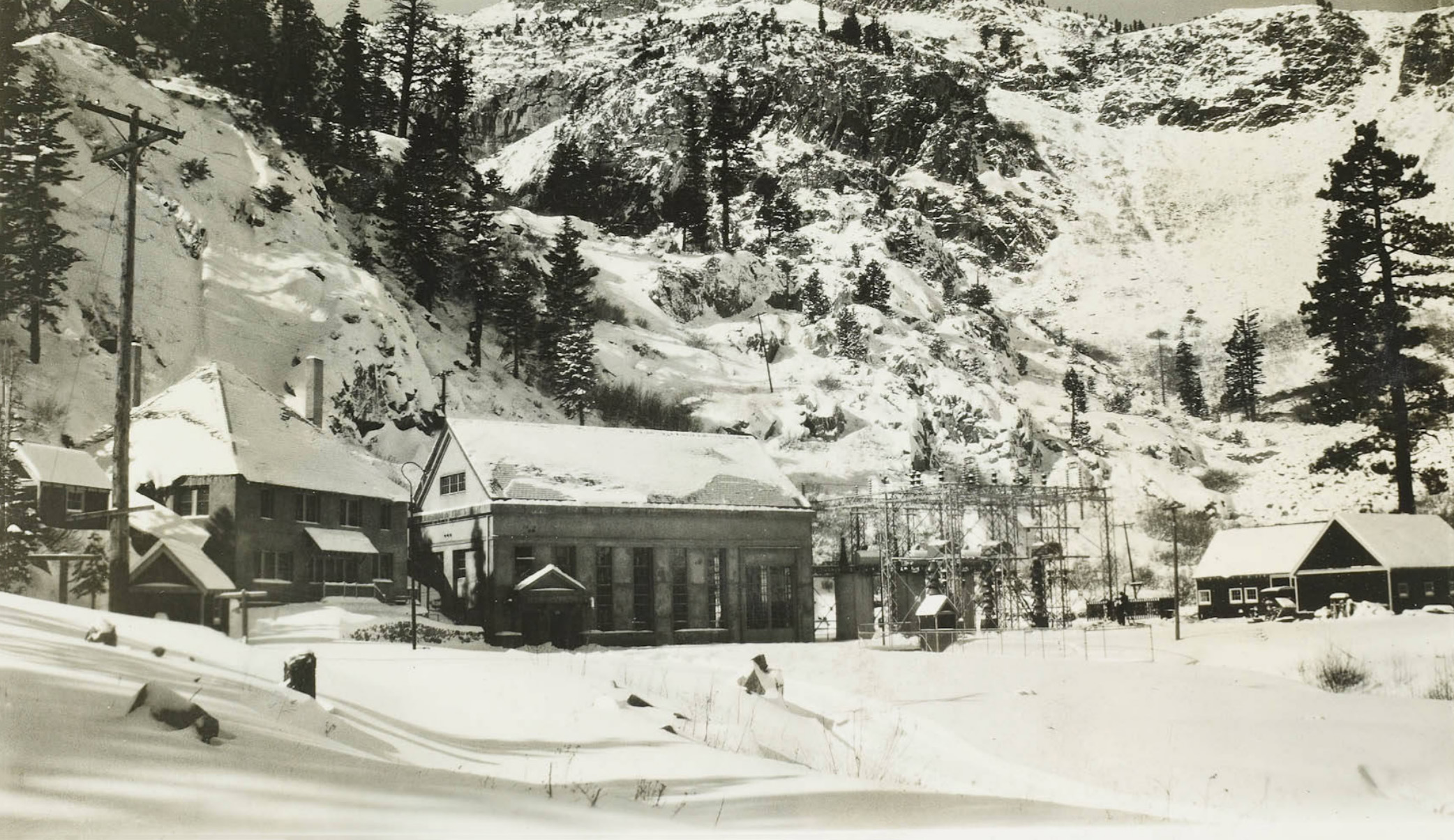
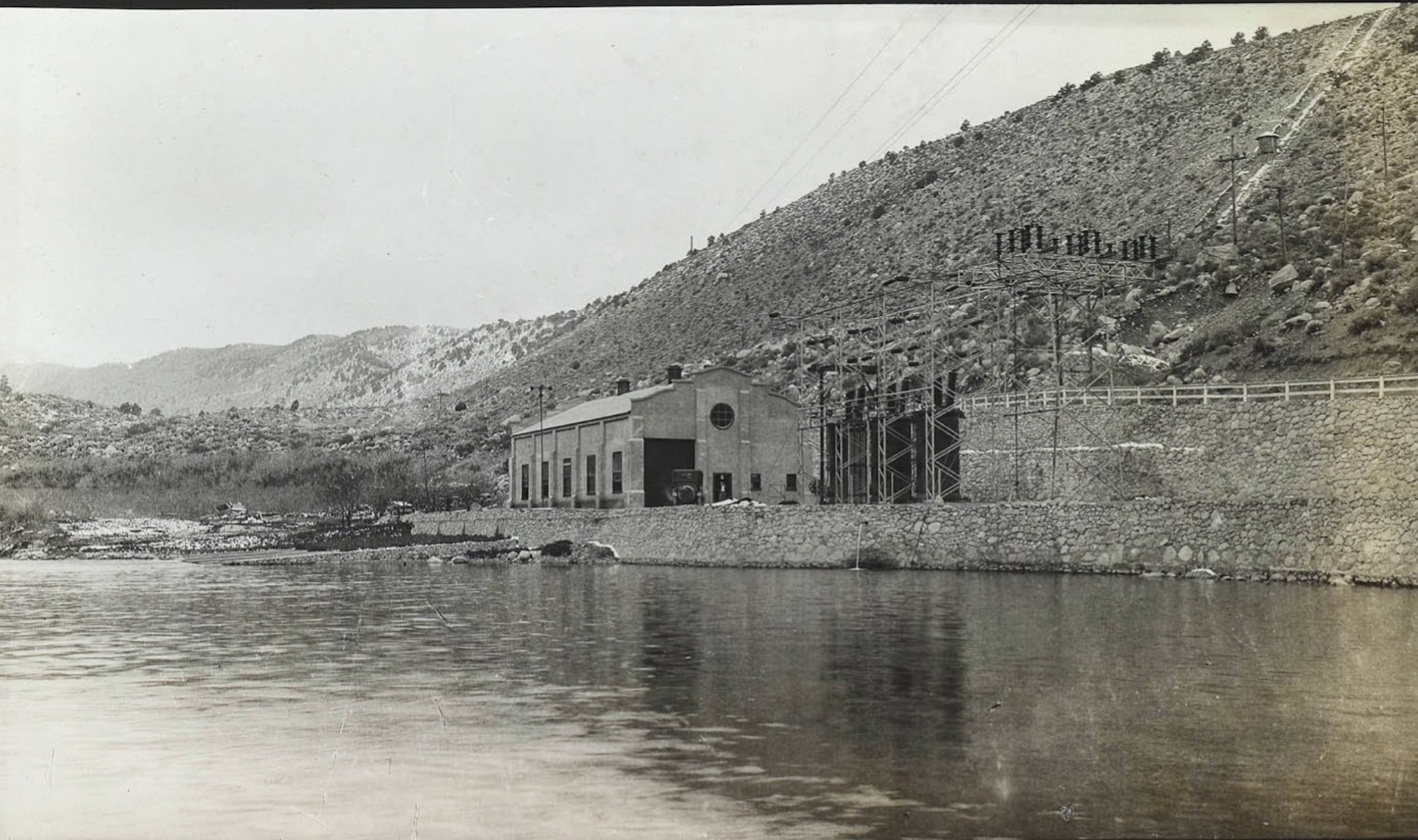
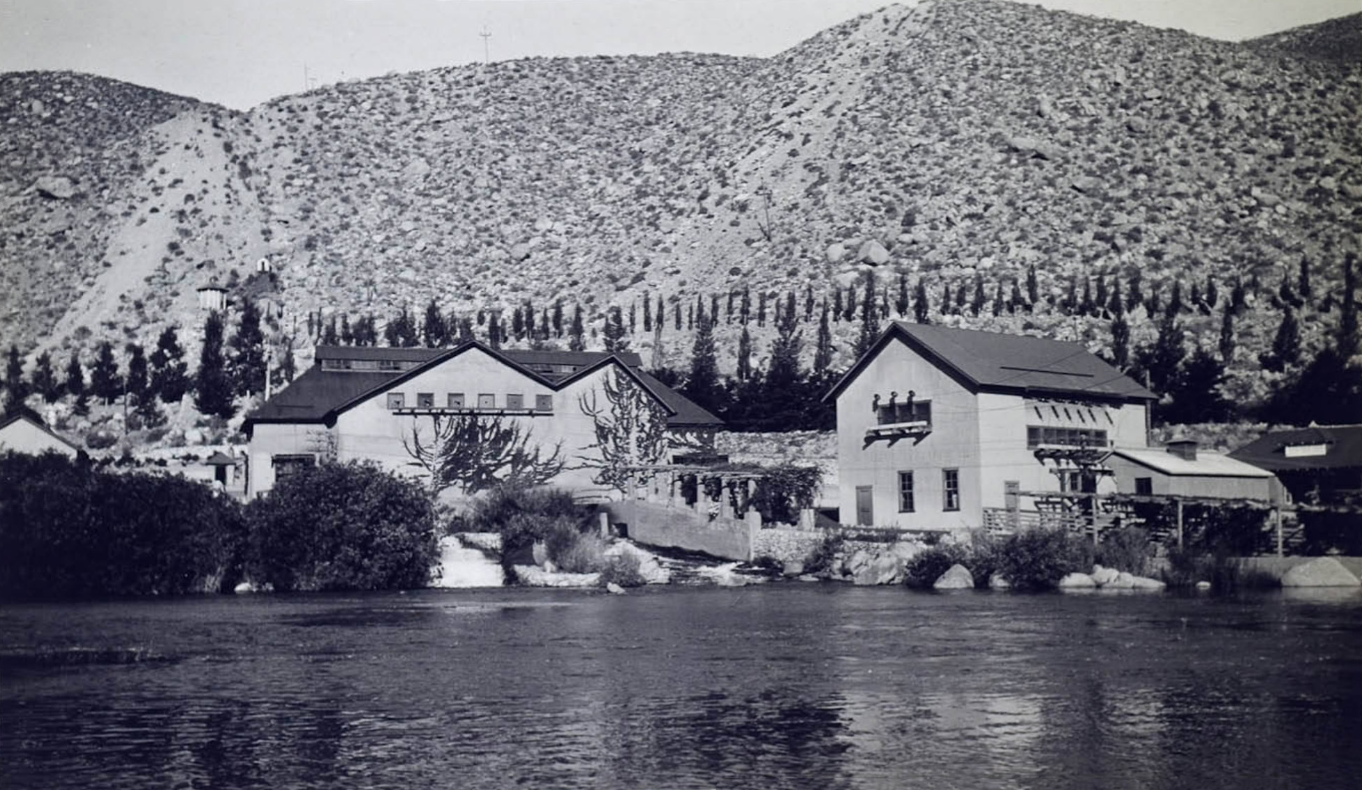
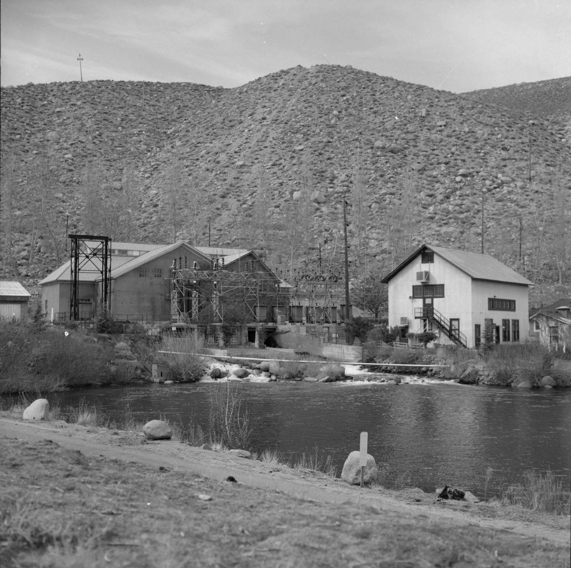
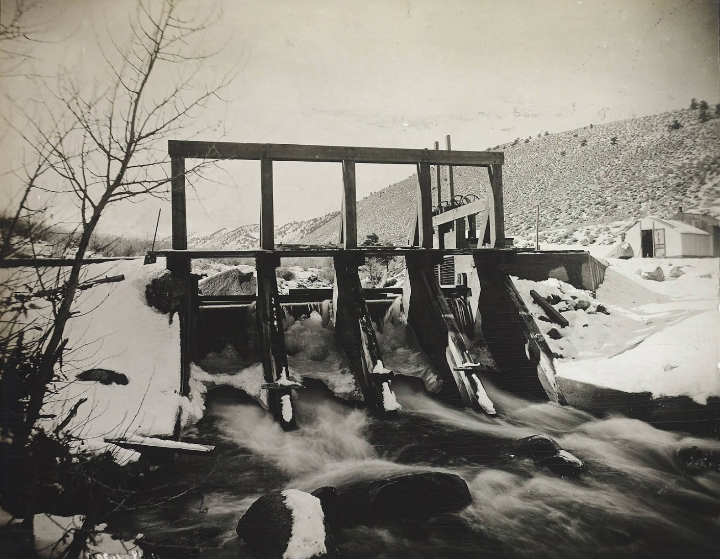
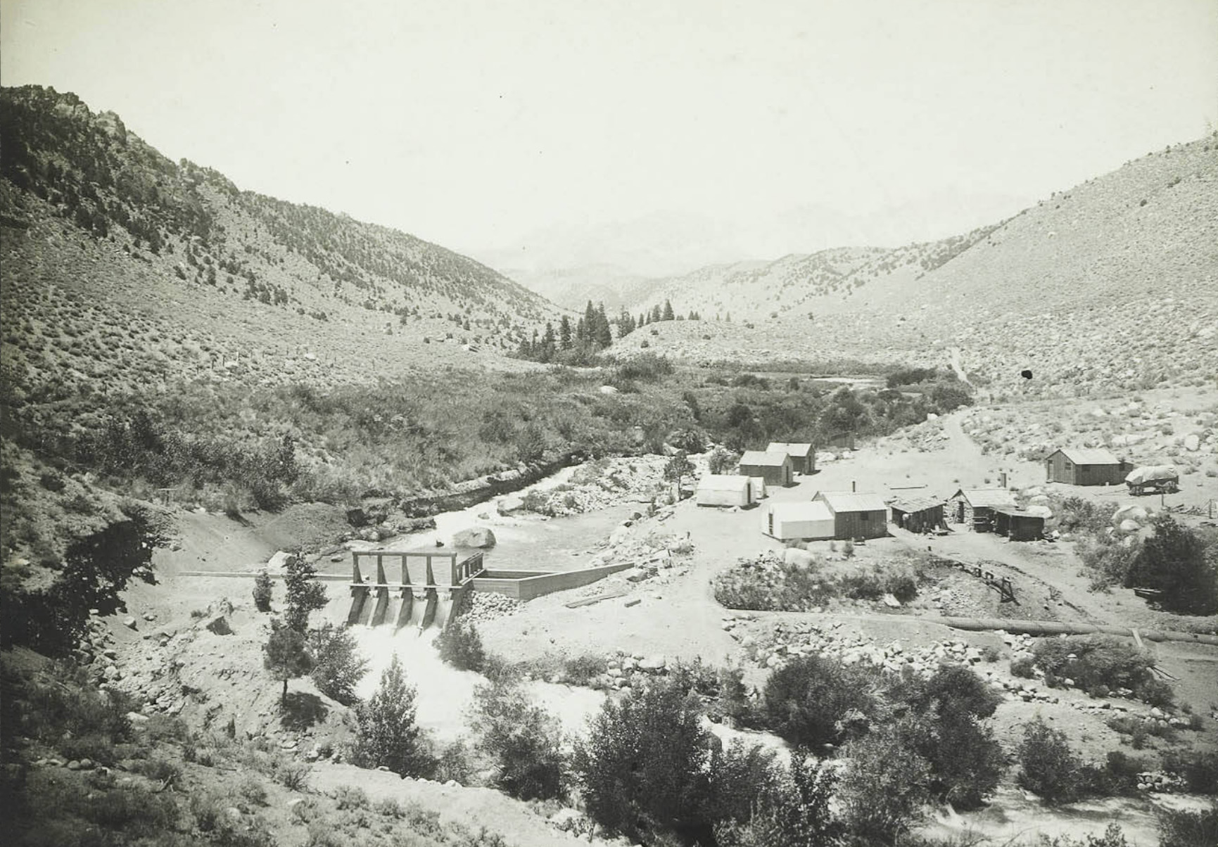
Jordan Powerhouse Mill Creek |
||
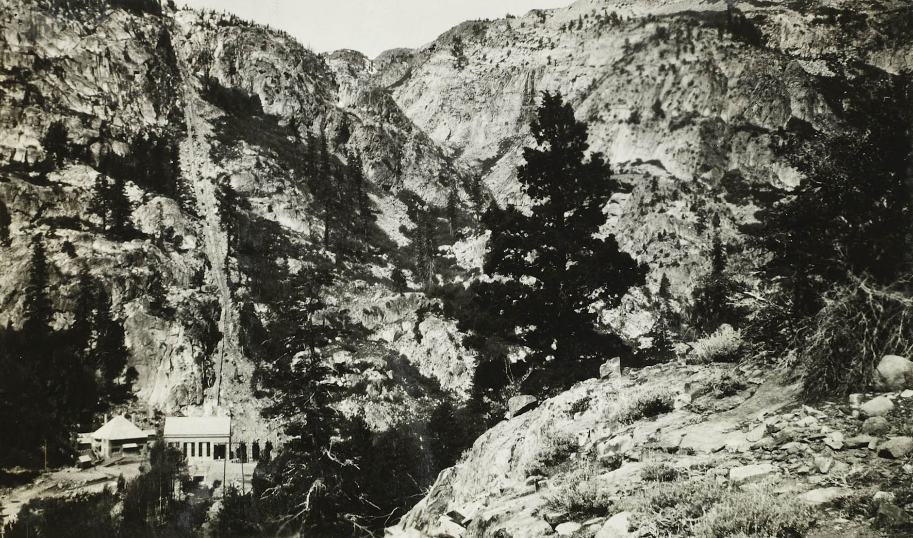
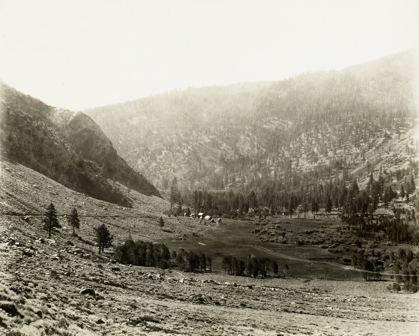
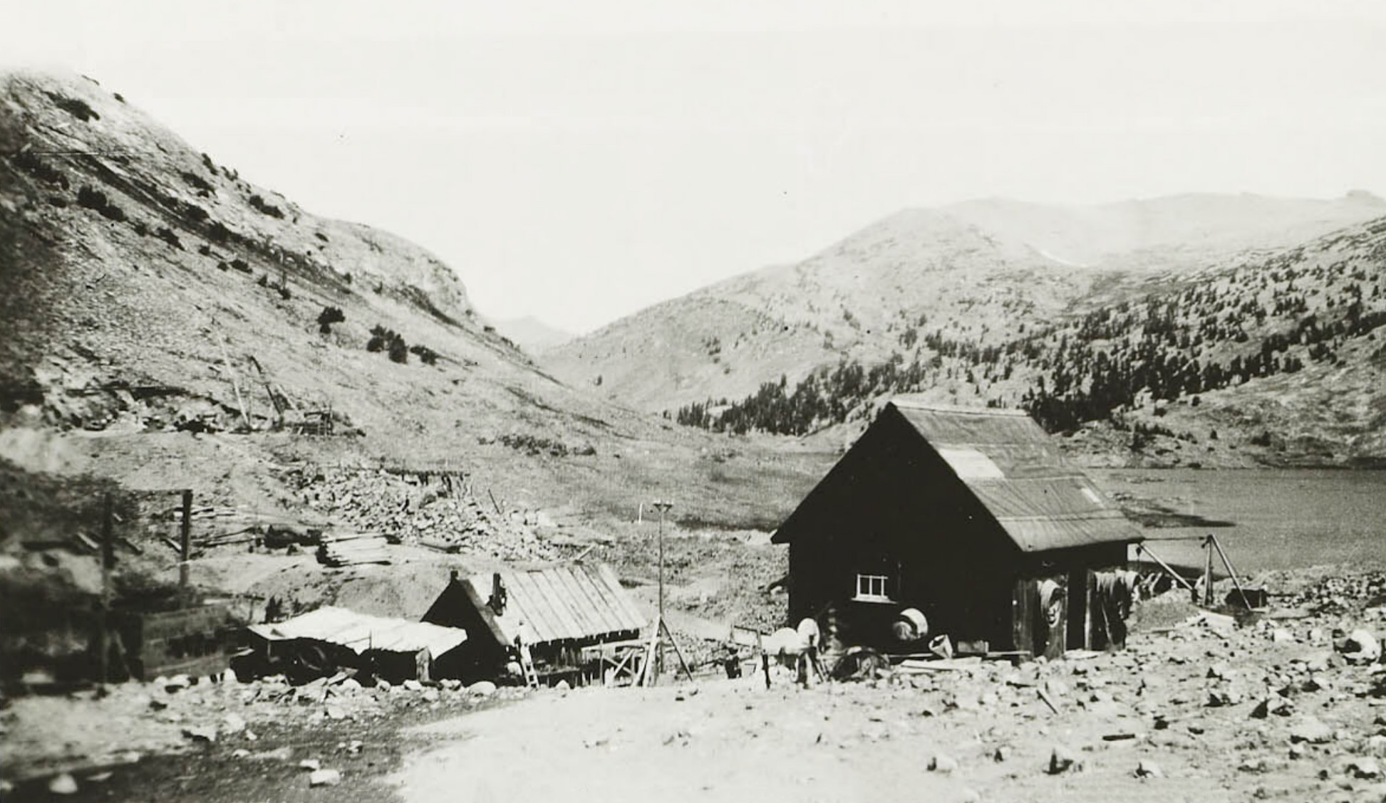
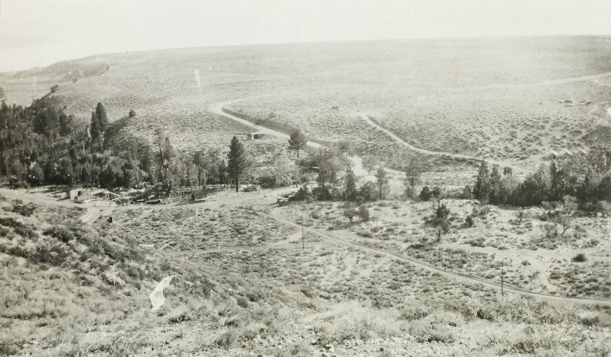
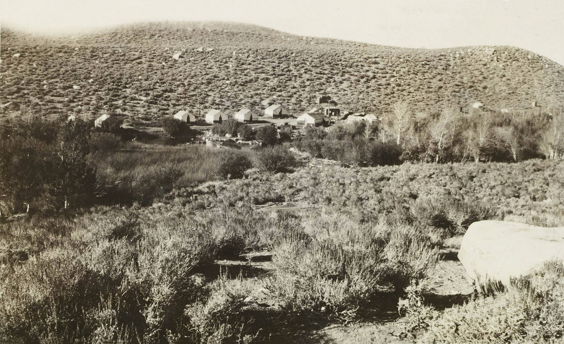
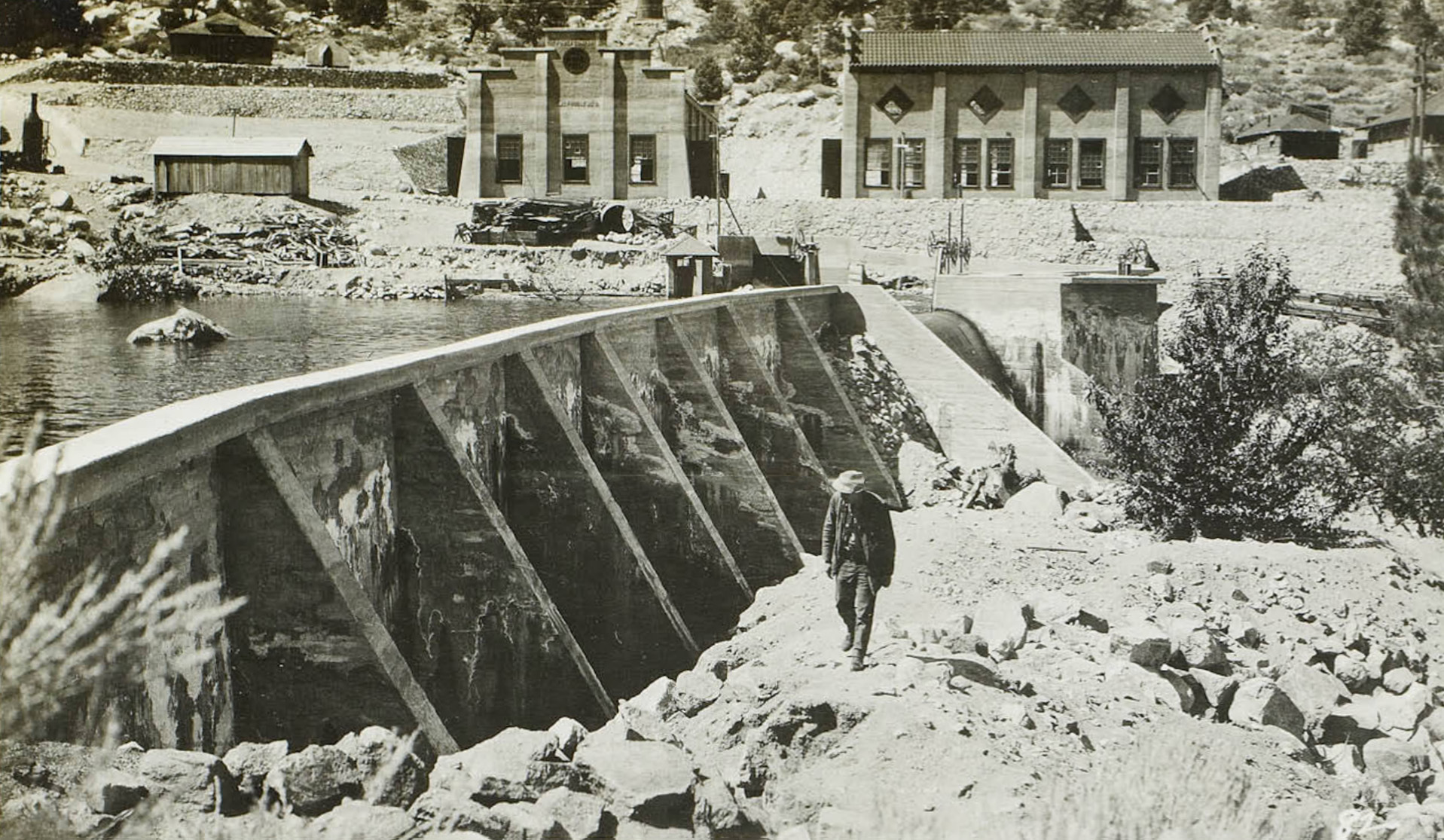
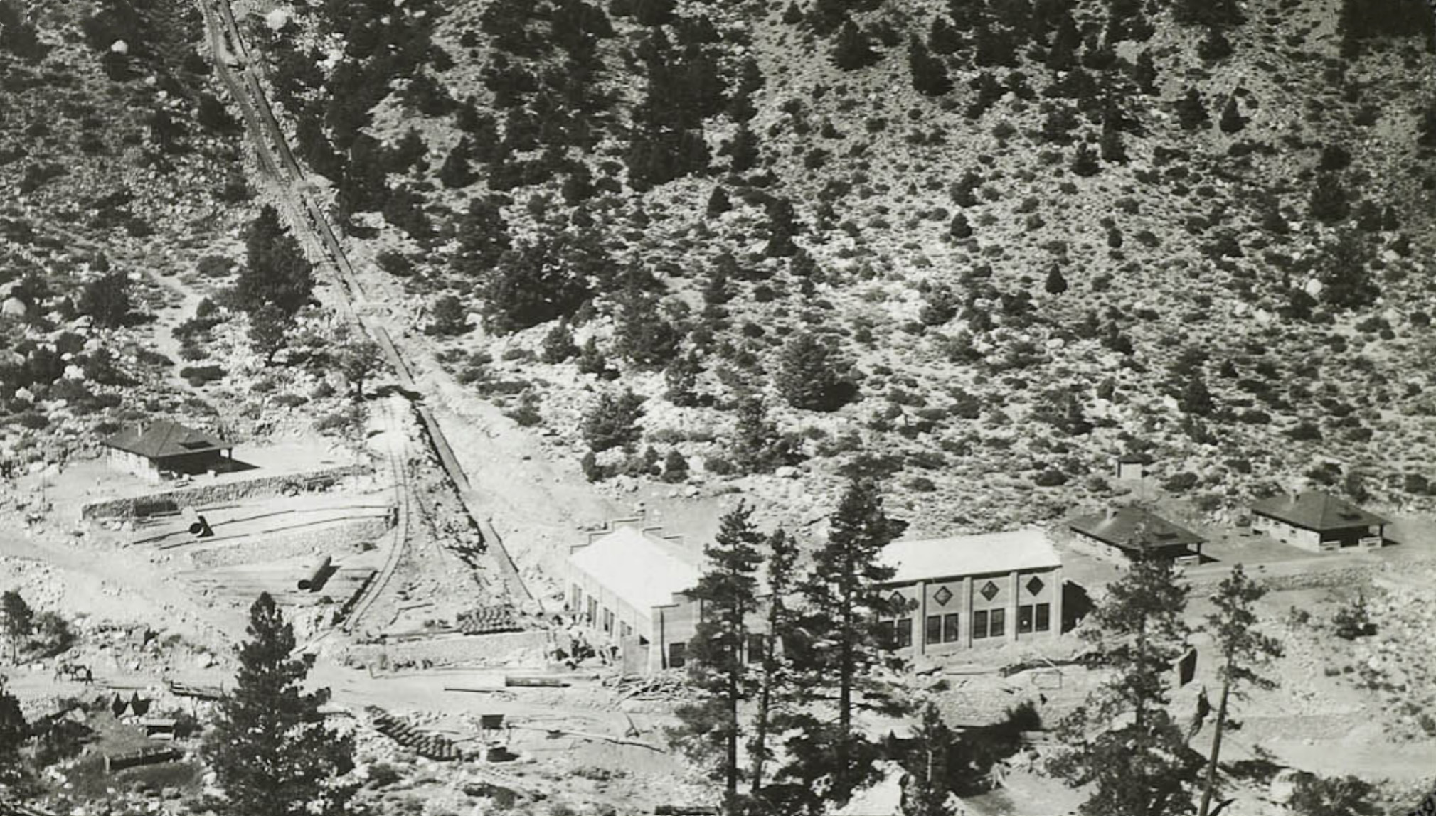
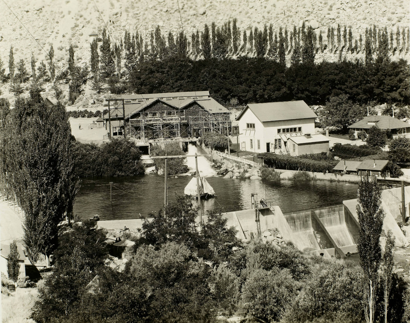
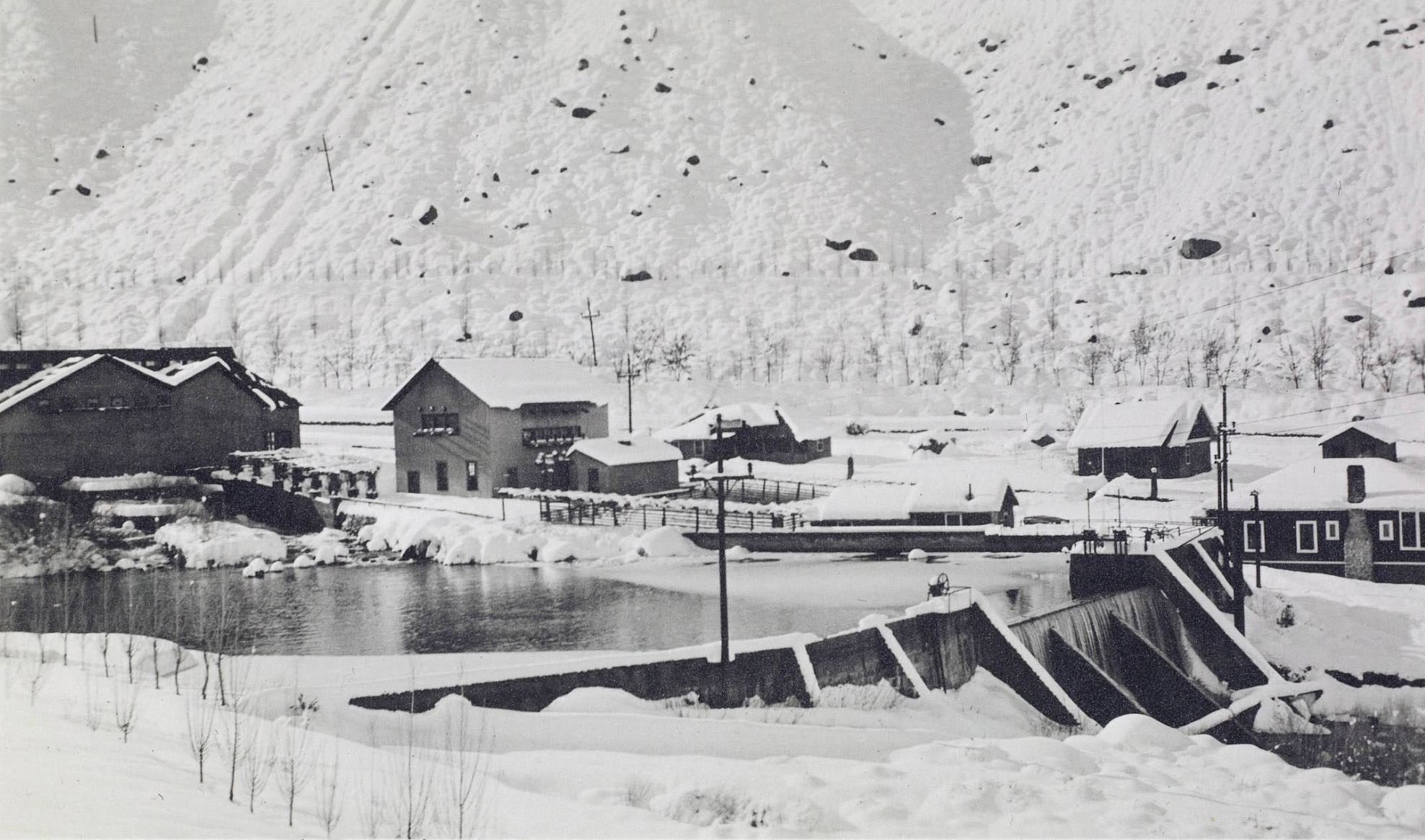
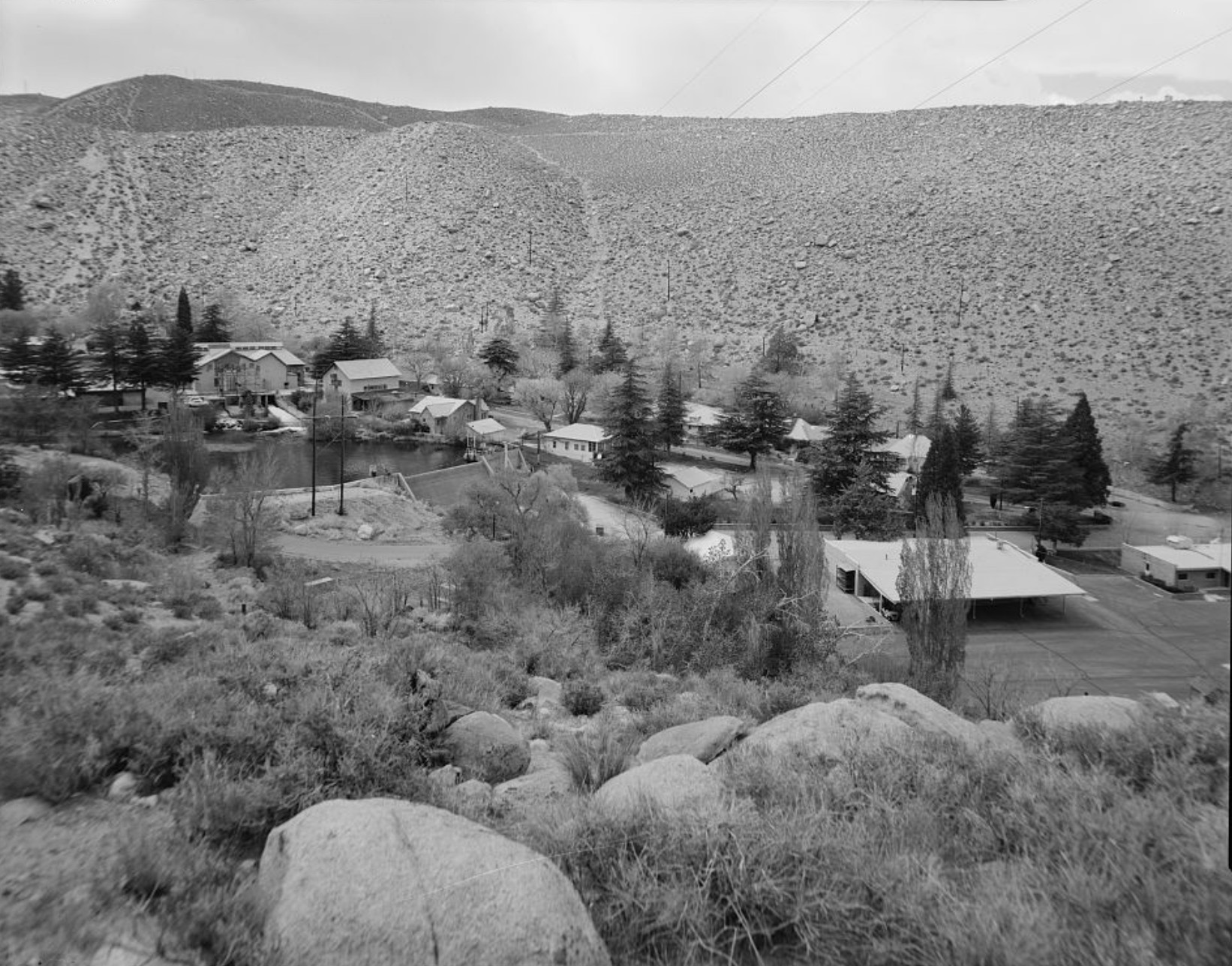
 View of the Jordan Power House Plant and the areas it supplied power to. |
||
Jordan Power House Disaster by Cecil Page Vargo
Avalanche on Copper Mountain (Jordan PH) by Roger Mitchell The Jordan Tragedy by Barbara Moore |
||
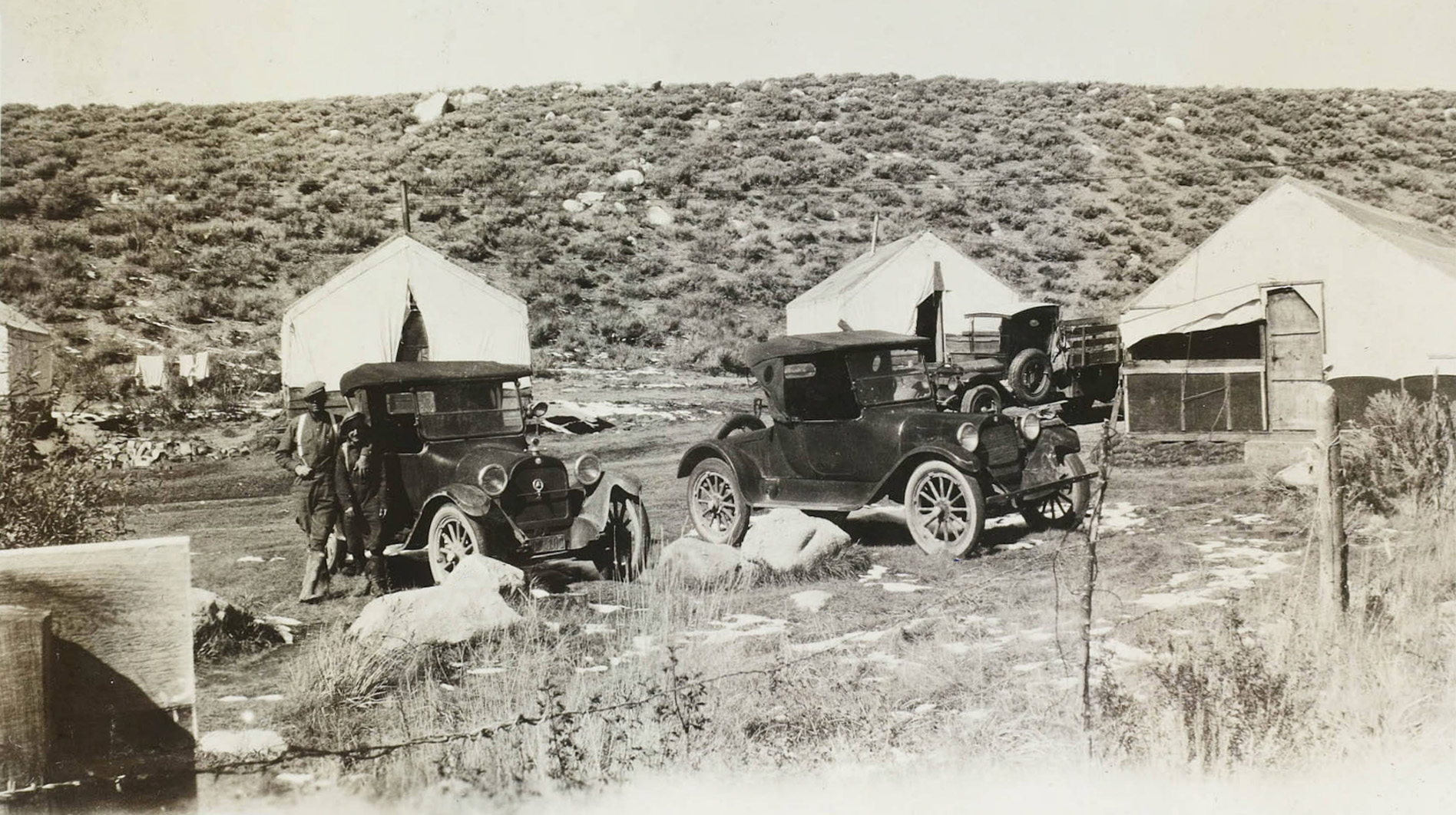
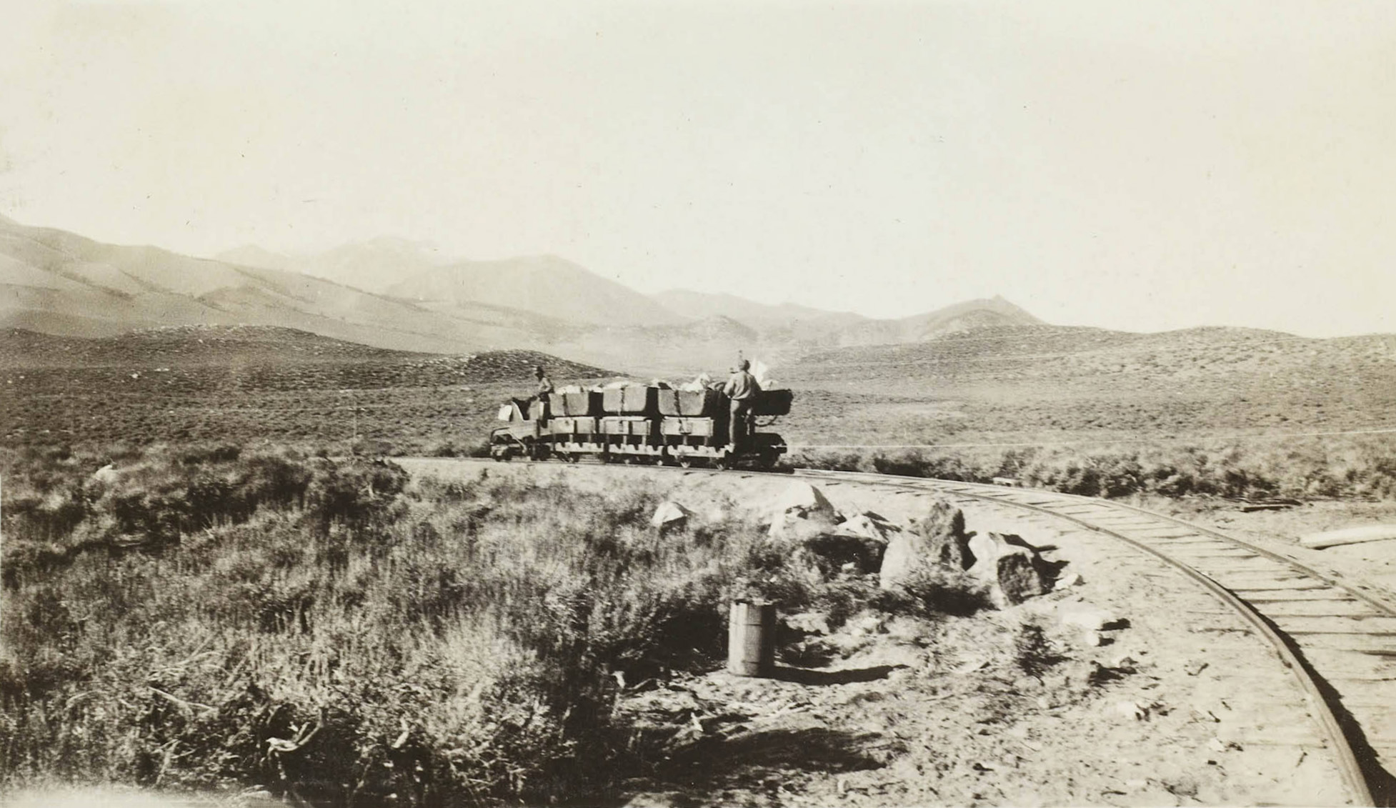
 Jordan Powerhouse survey team after the avalanche heading out to the plant site. |
||
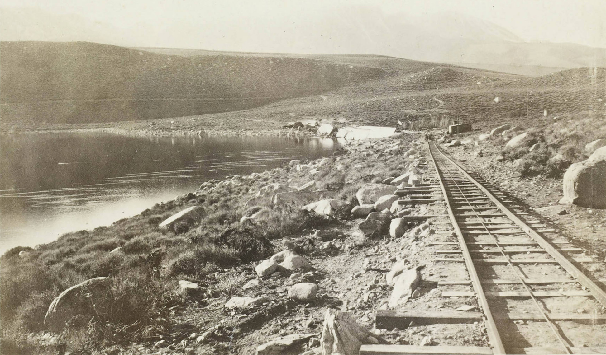
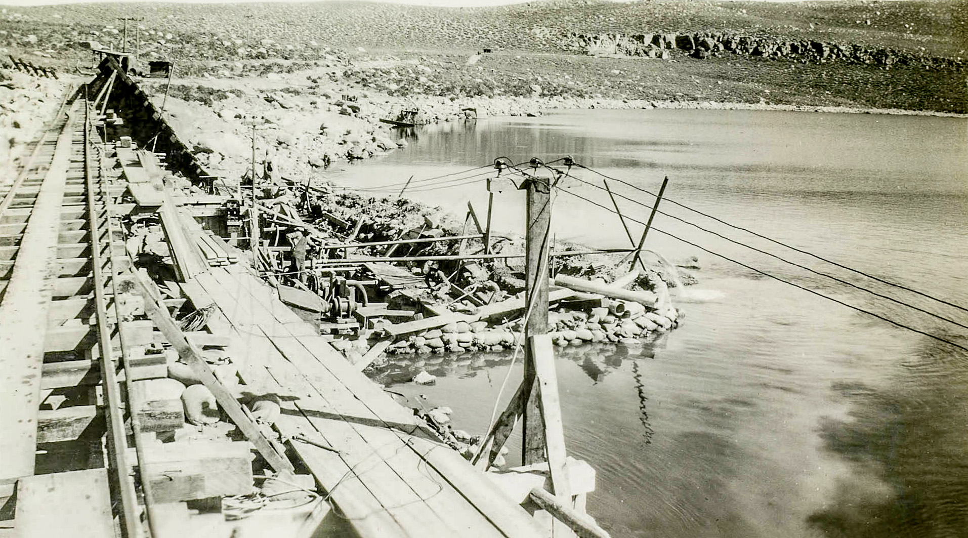
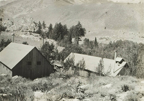
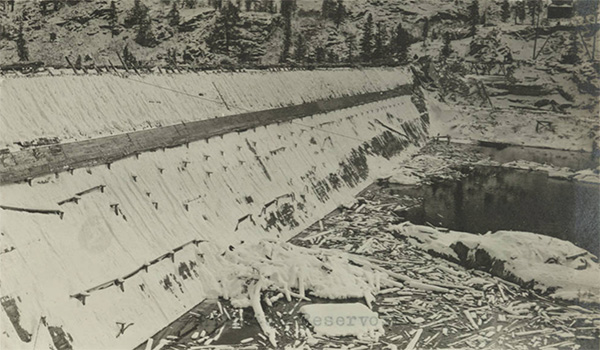
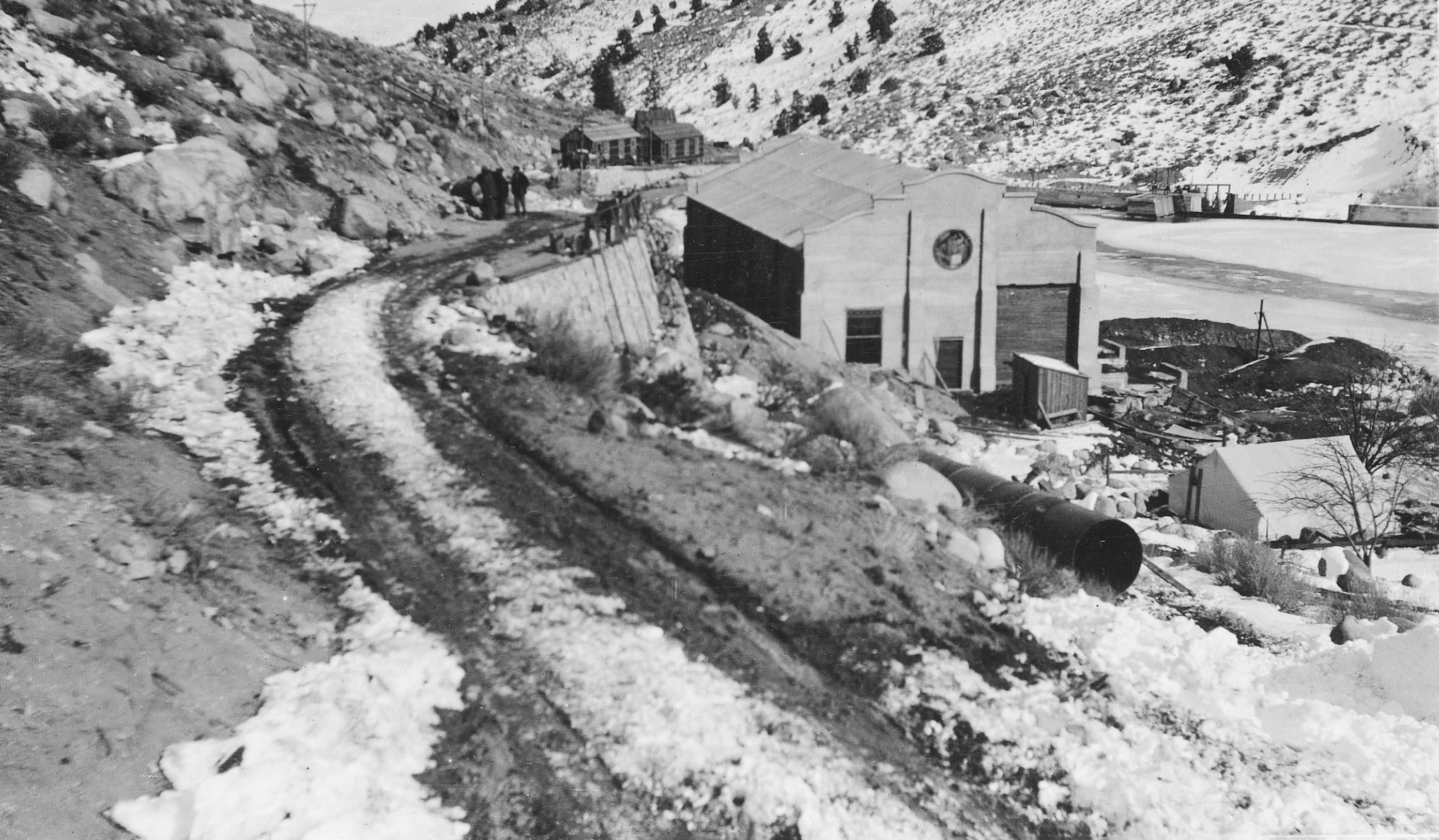
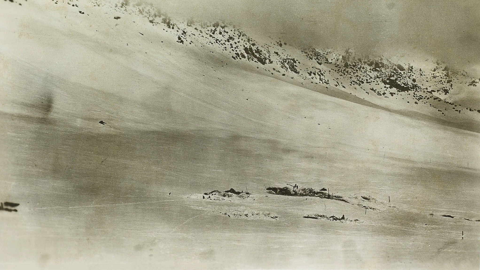 All that remains of the Jordan Powerhouse complex after the avalanche |
||
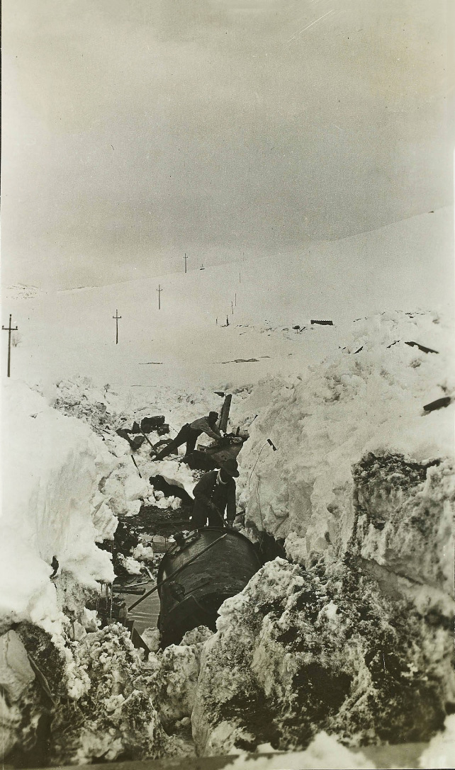
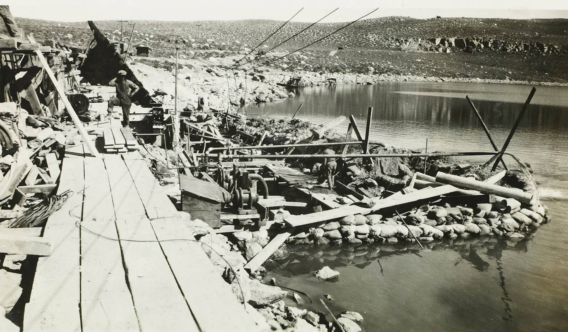
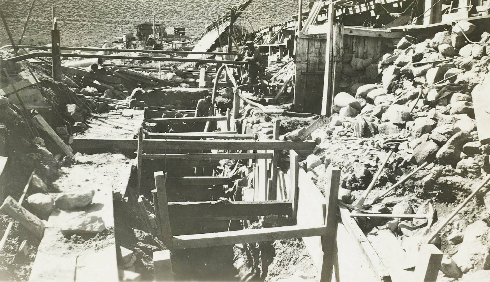
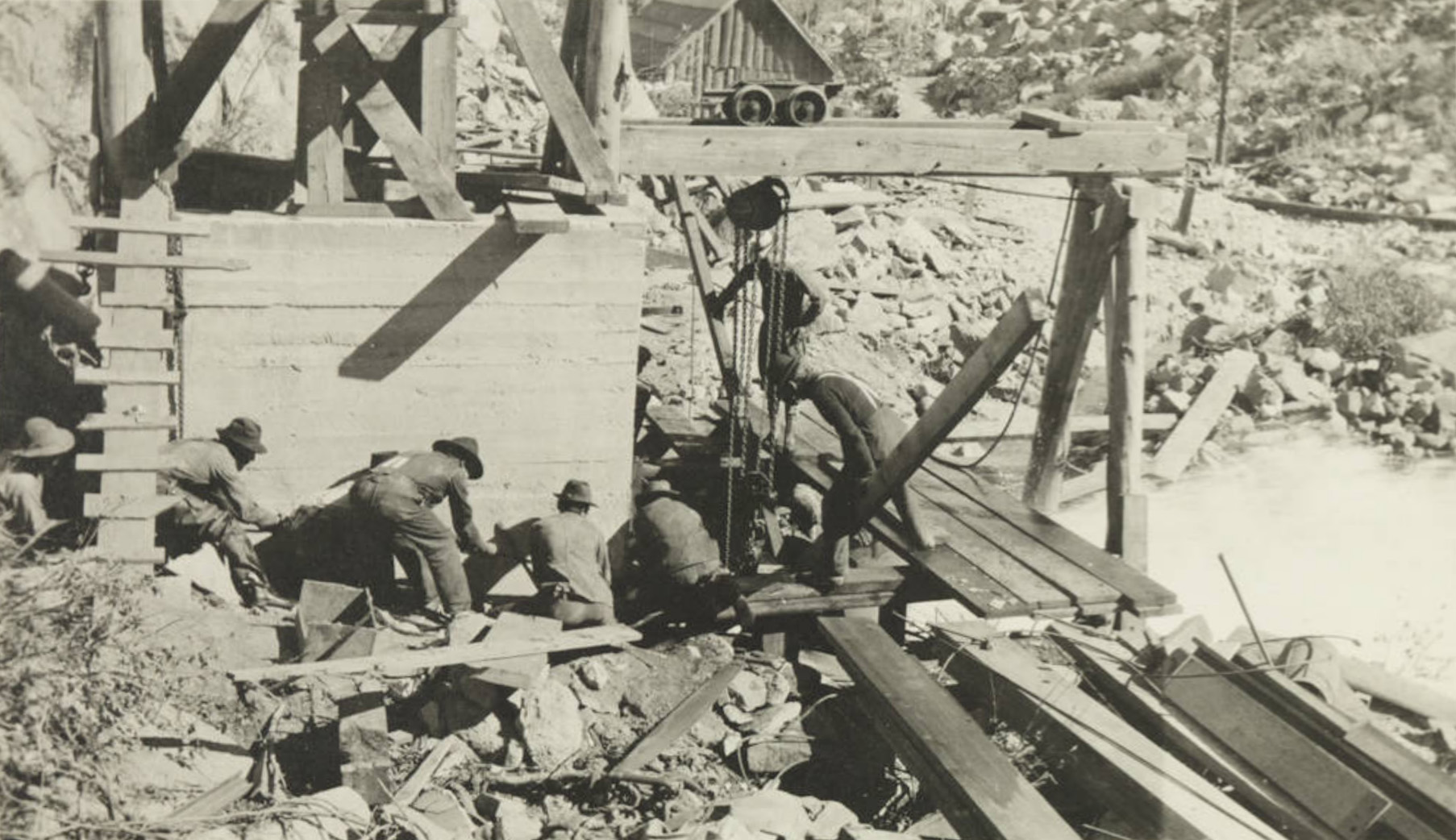
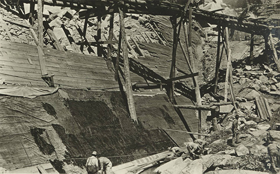
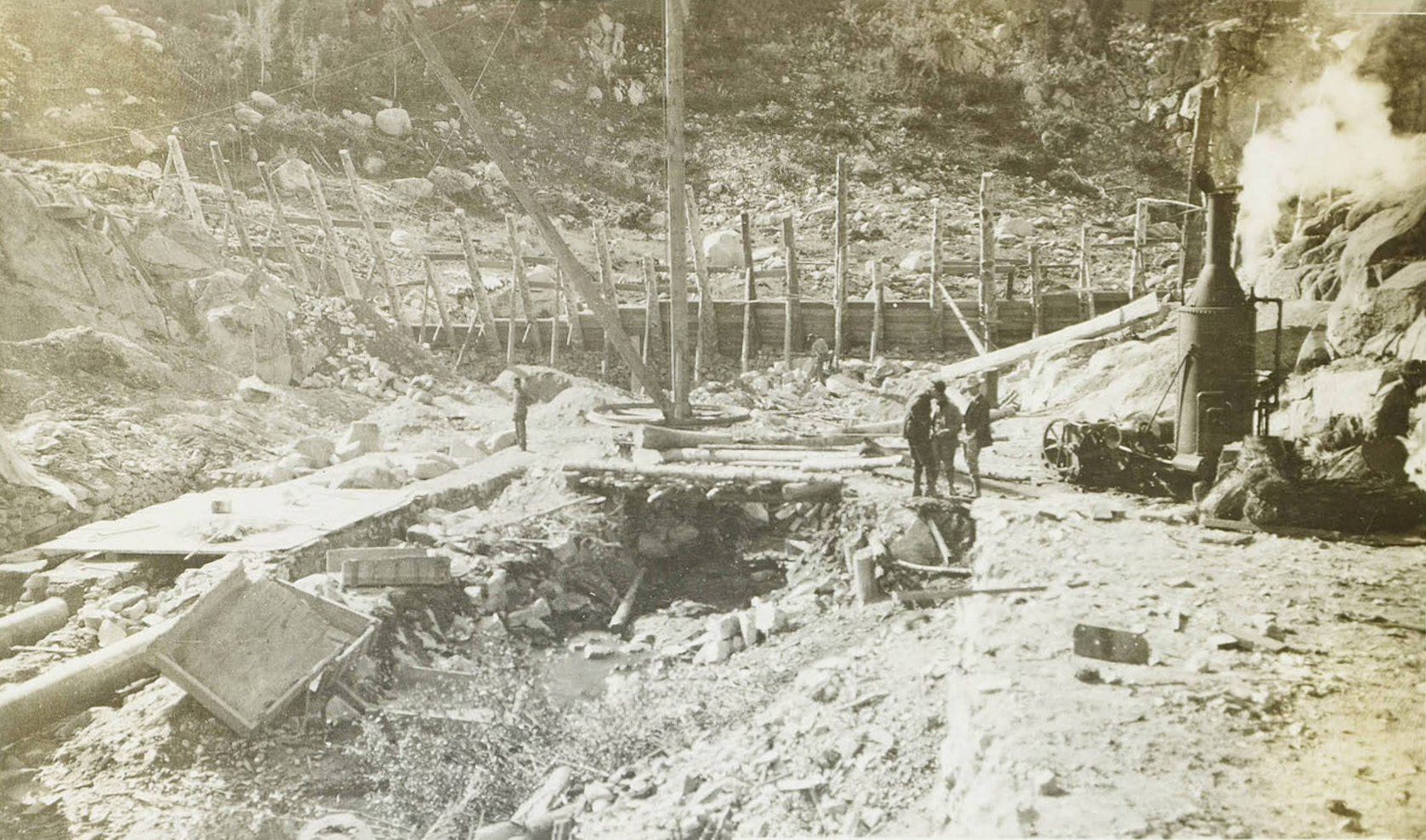
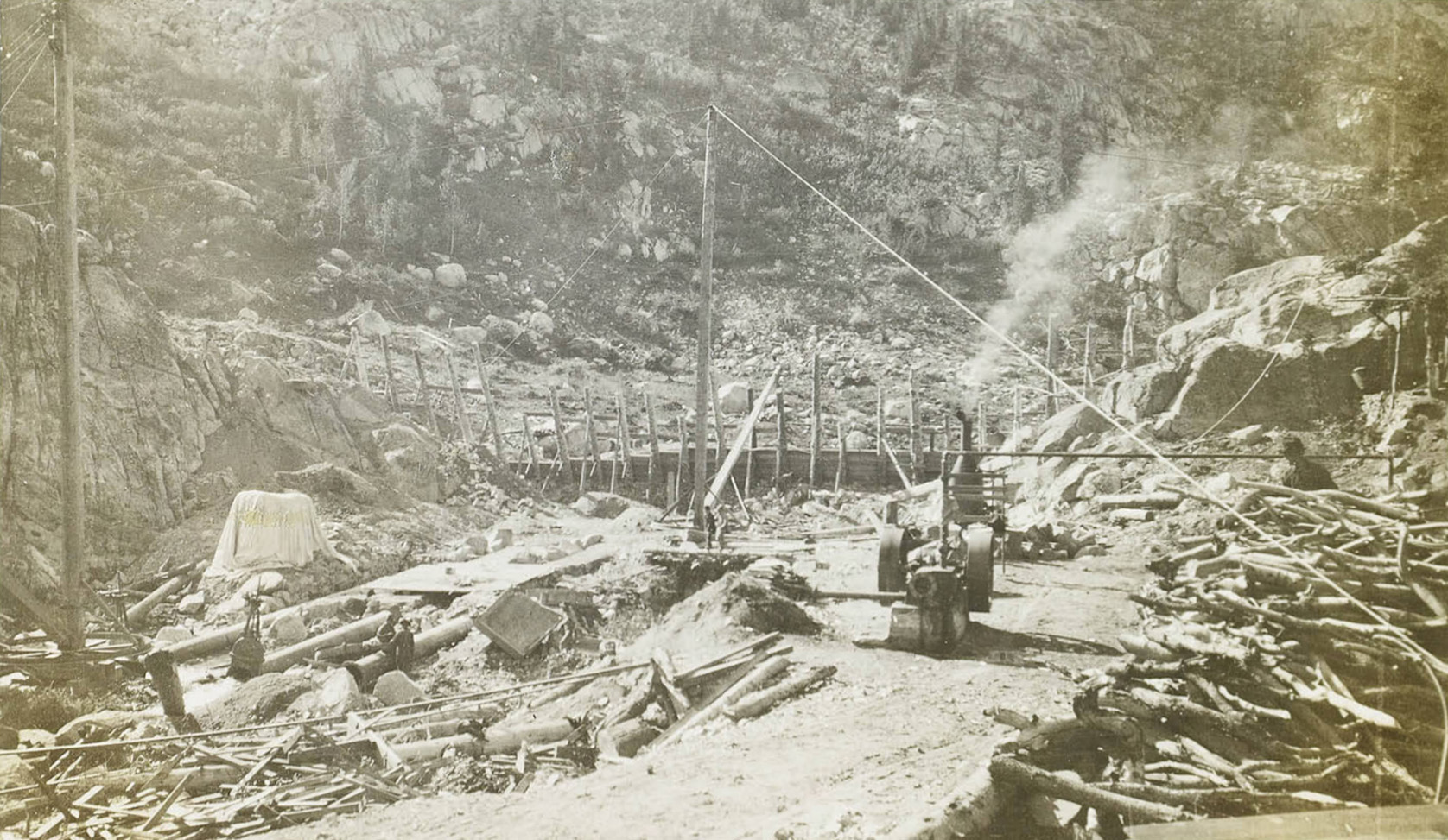
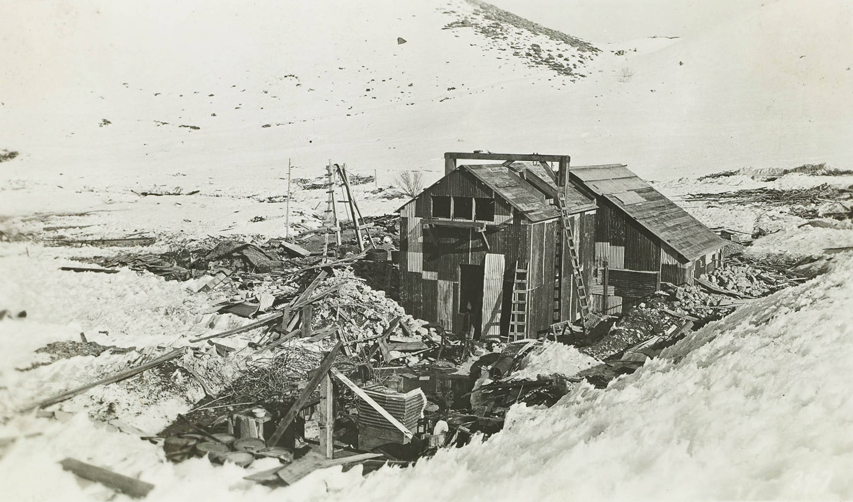 Jordan Powerhouse after avalanche 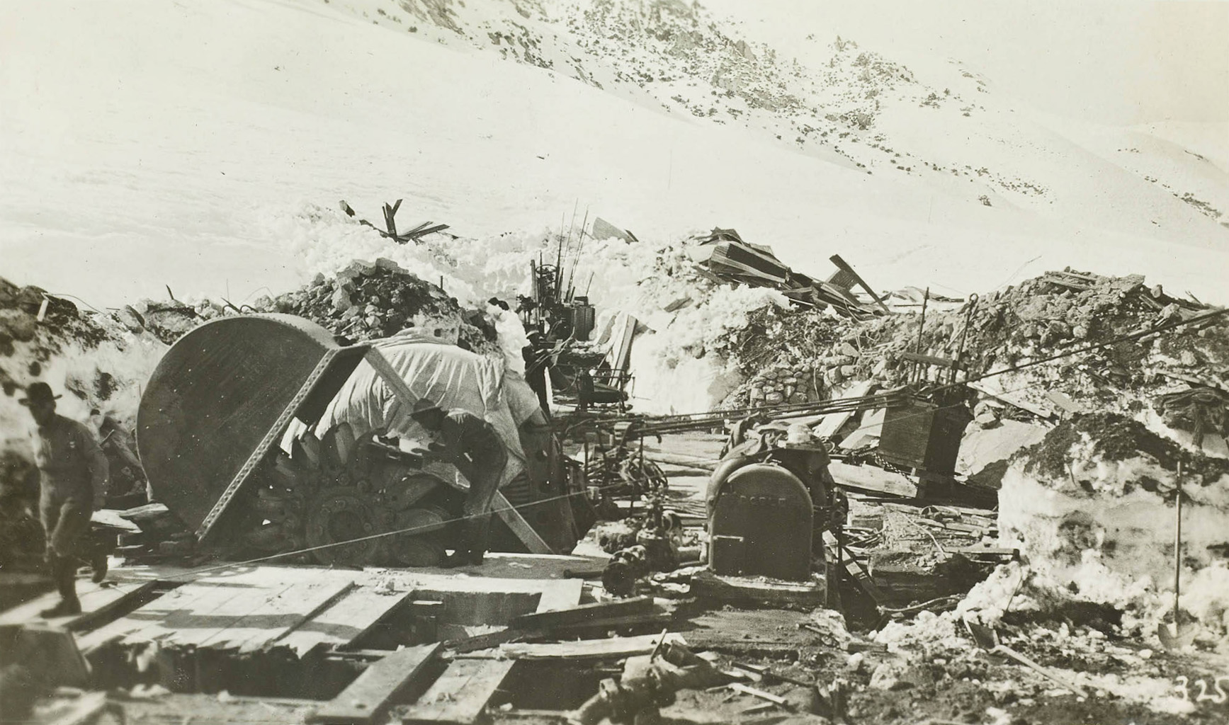 Jordan Powerhouse after avalanche 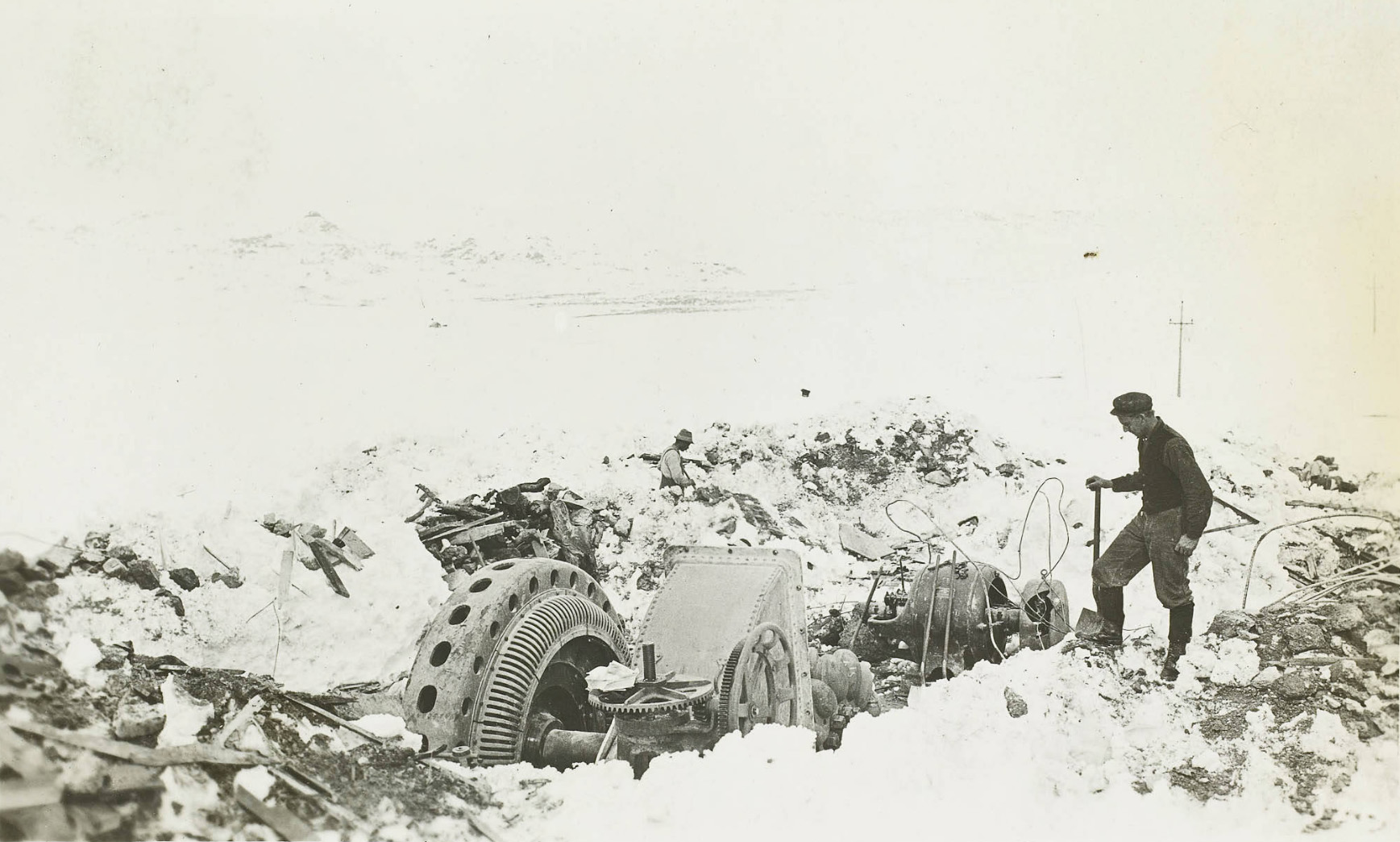 Digging out the remains of the Jordan Powerhouse after the avalanche |
 Joy Hunter ready to gather wild horses, wild burros or cattle. |
|
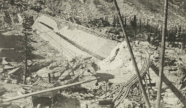
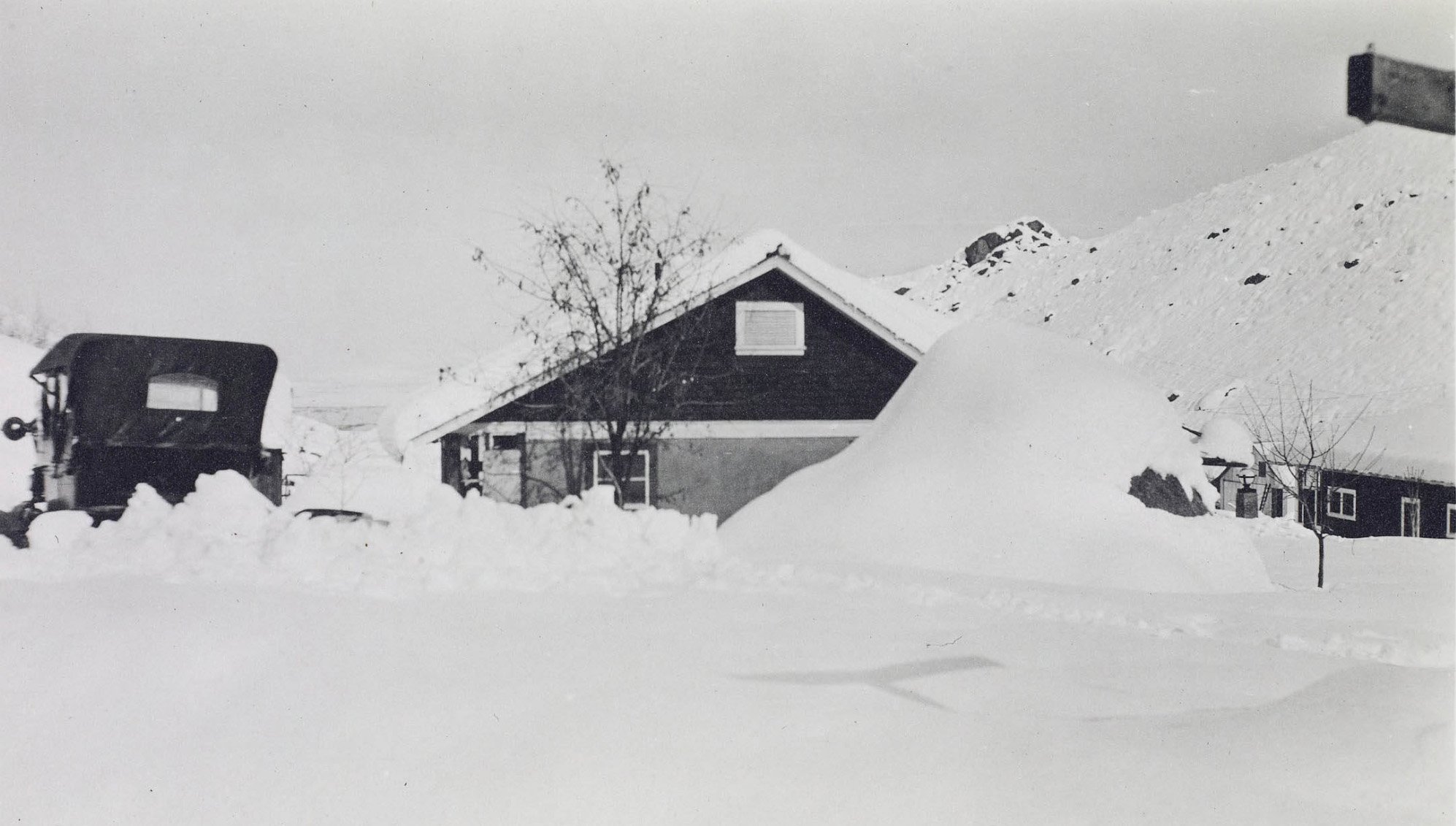
Jordan Powerhouse after avalanche |
||
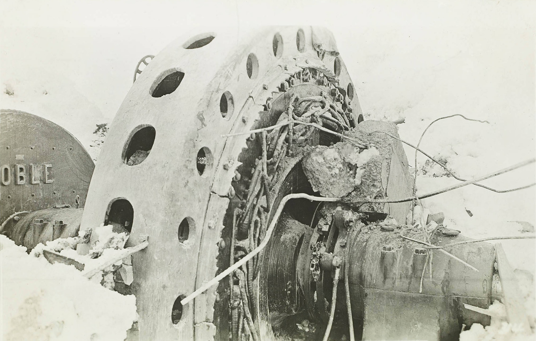 Jordan Powerhouse after avalanche |
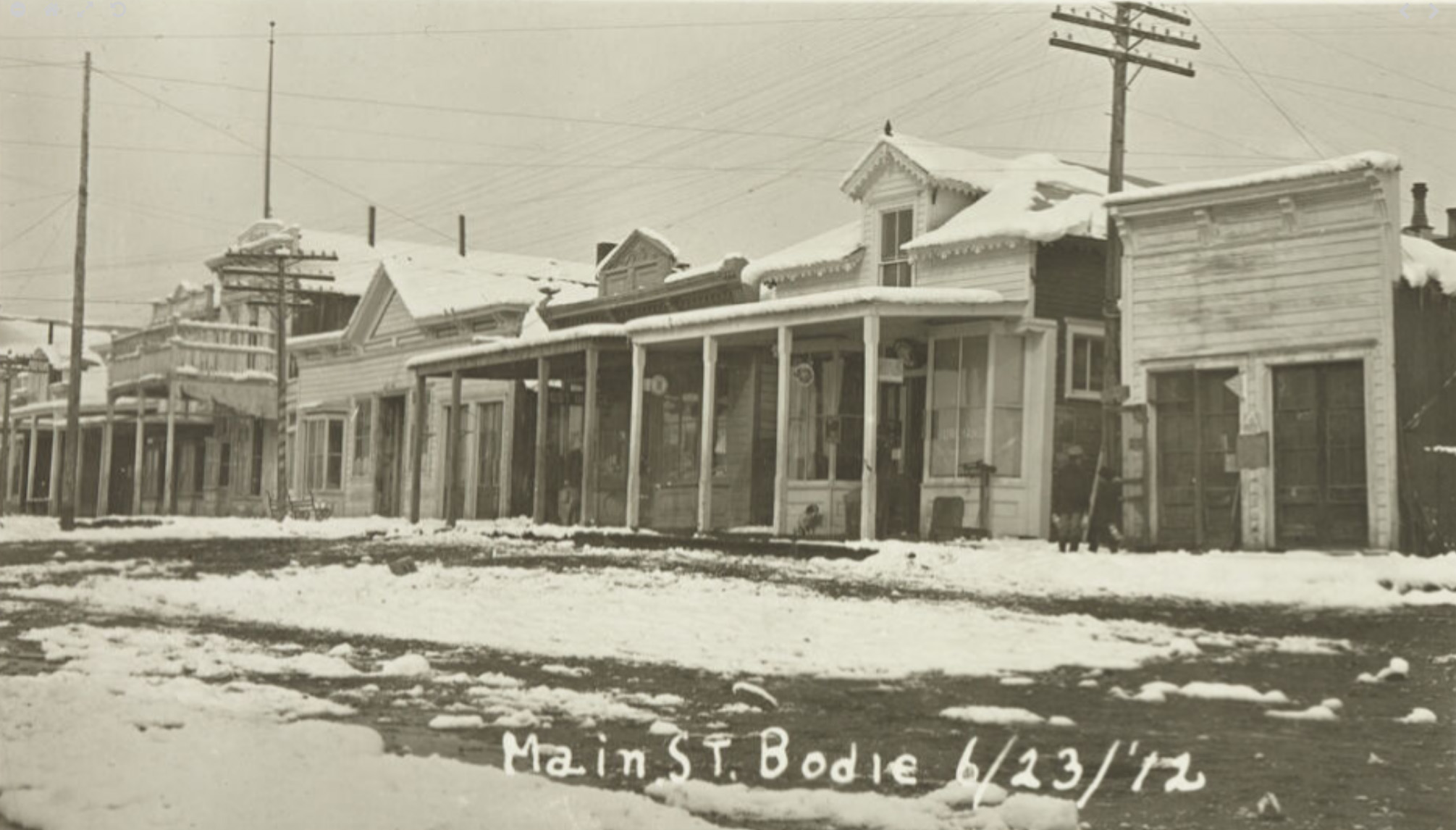 Bodie - 1912 - being supplied electricity by the Jordan Powerhouse |
|
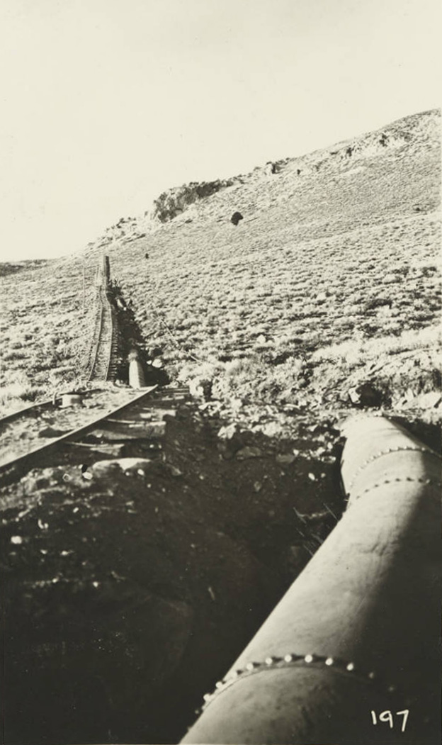
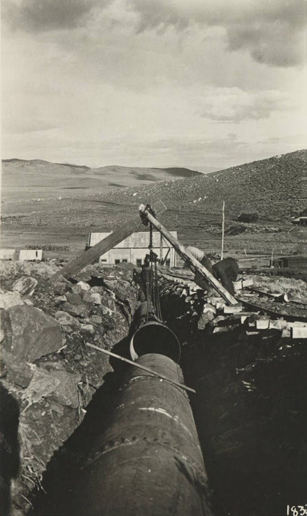
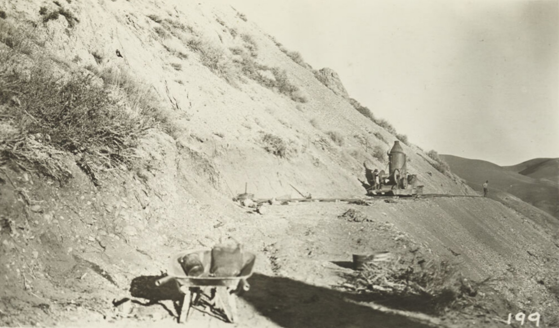
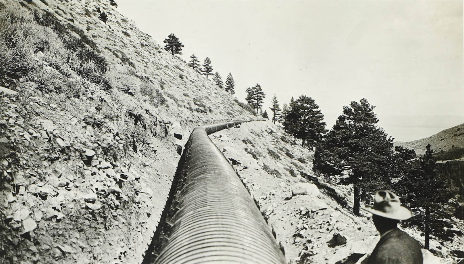
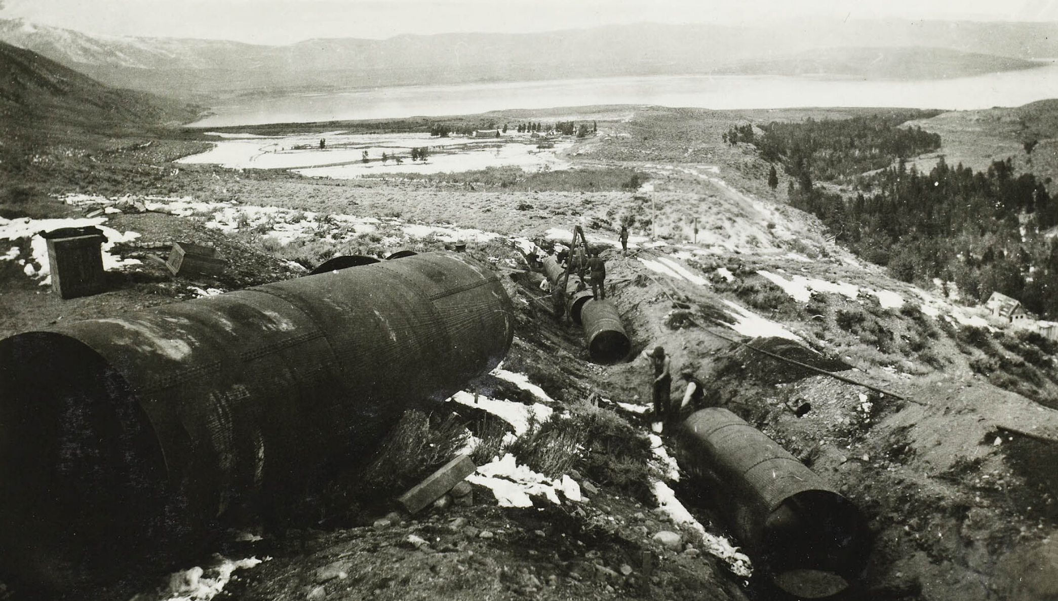
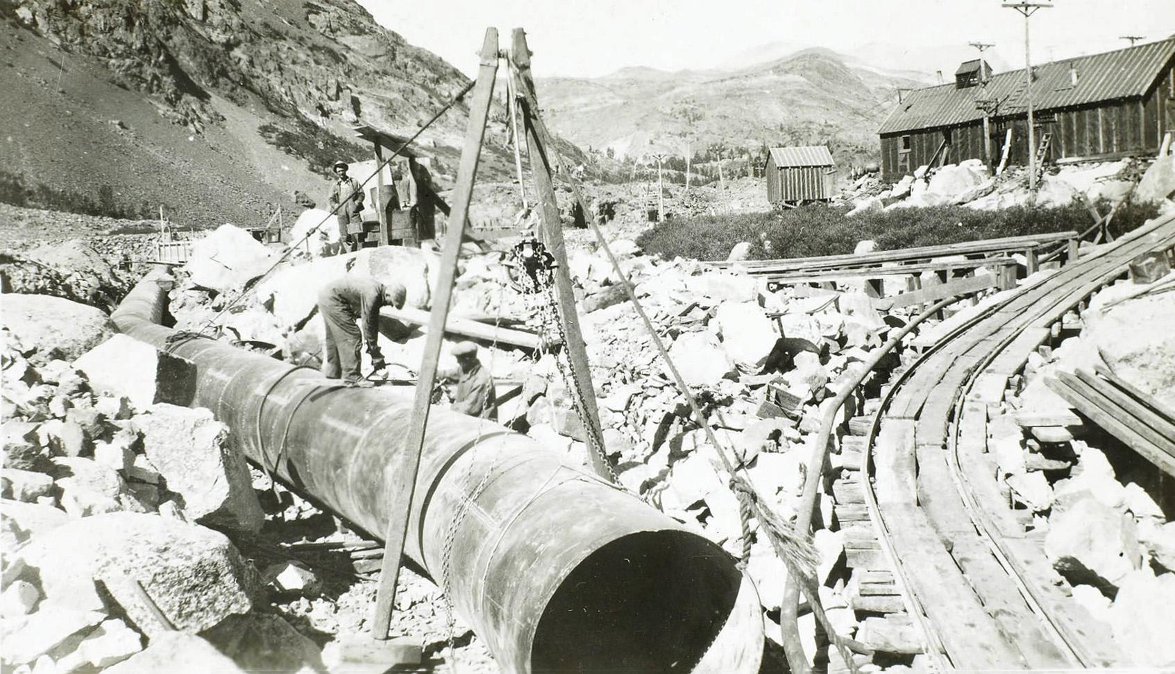
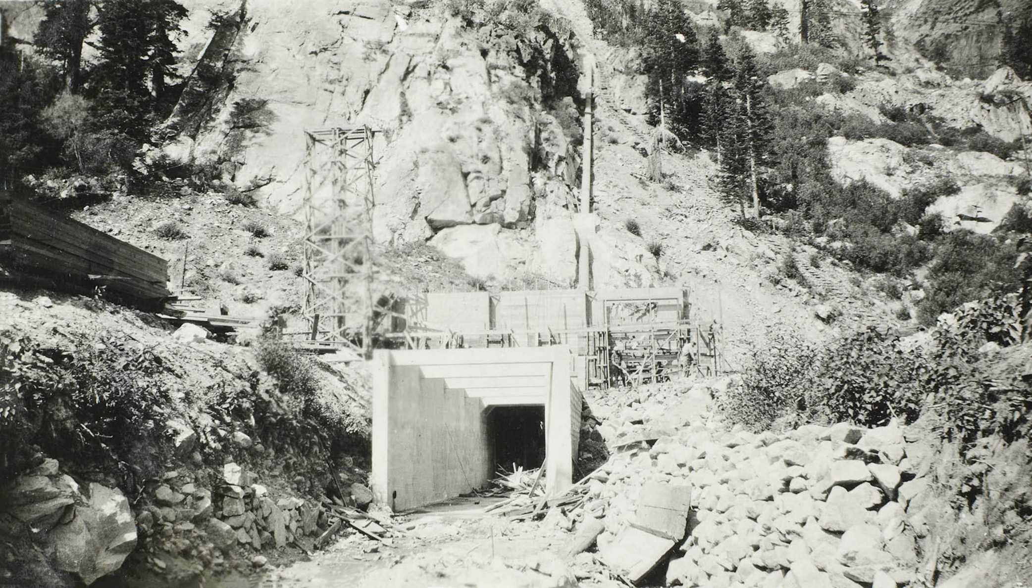
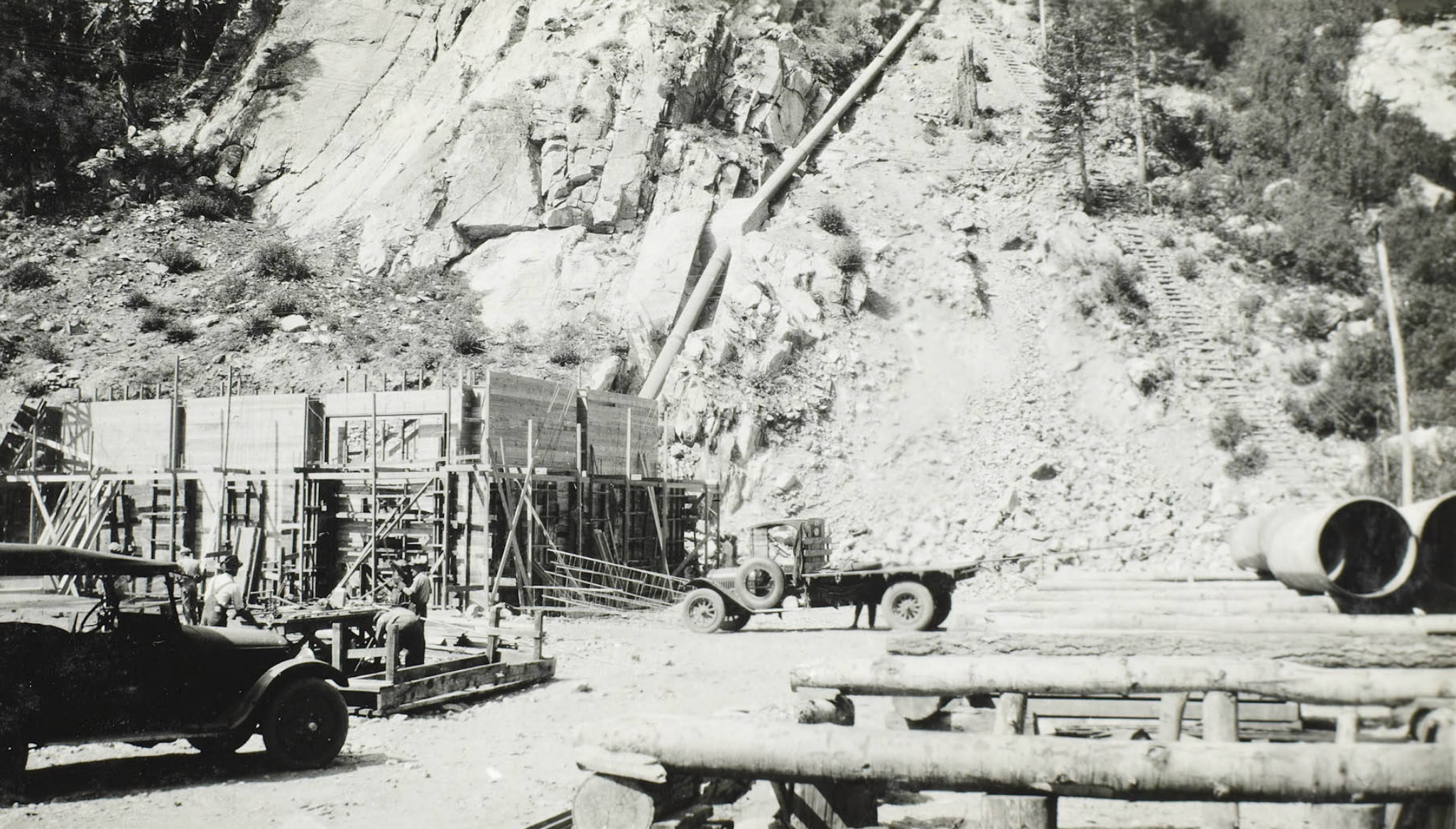
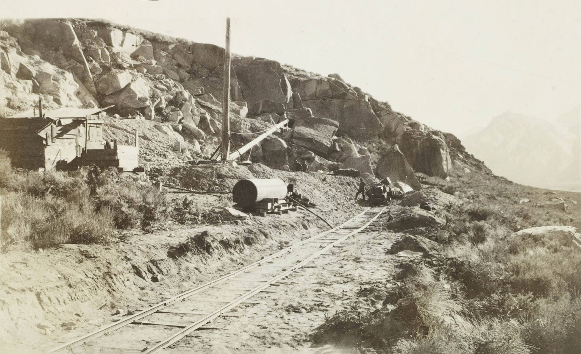
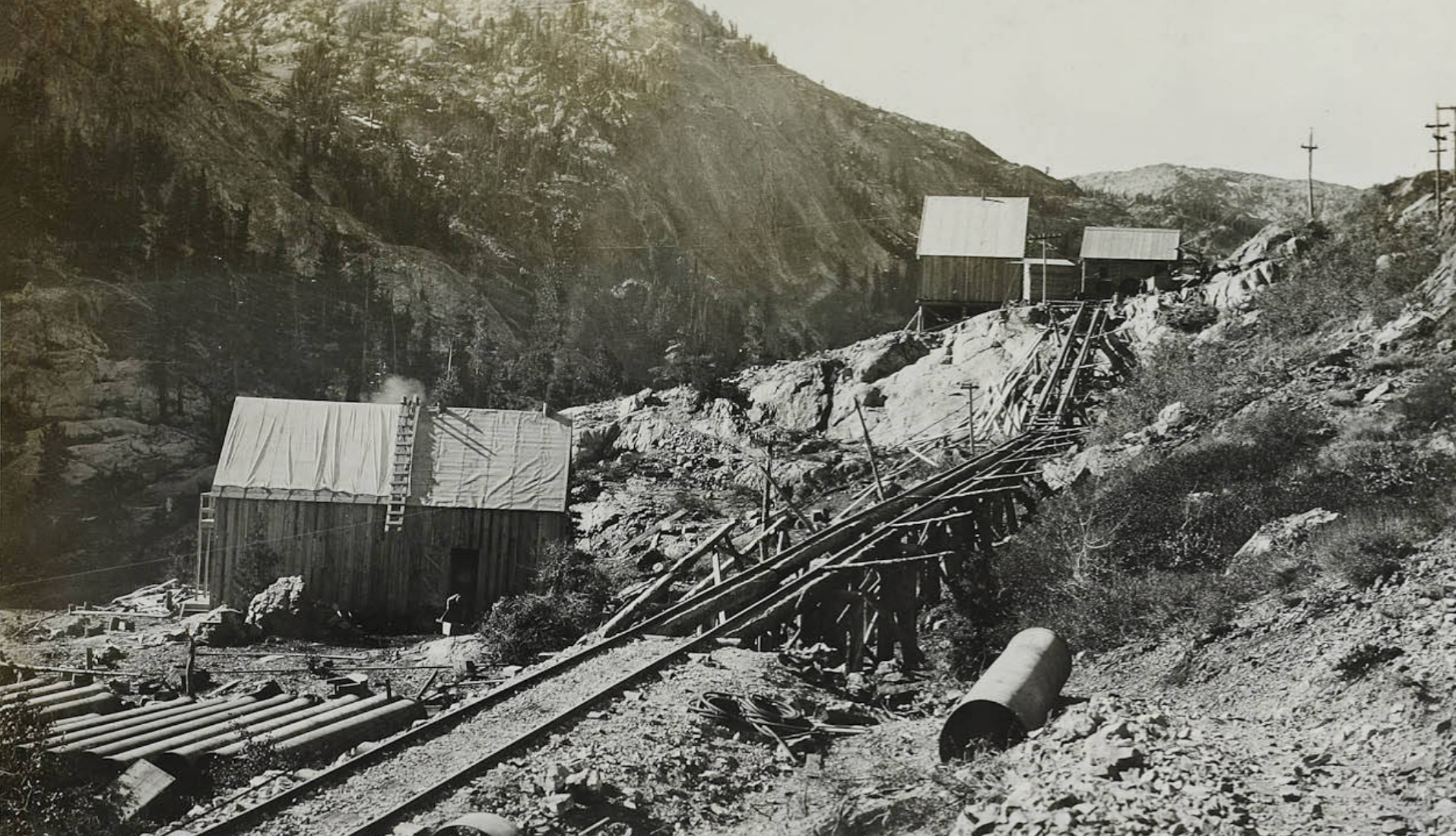
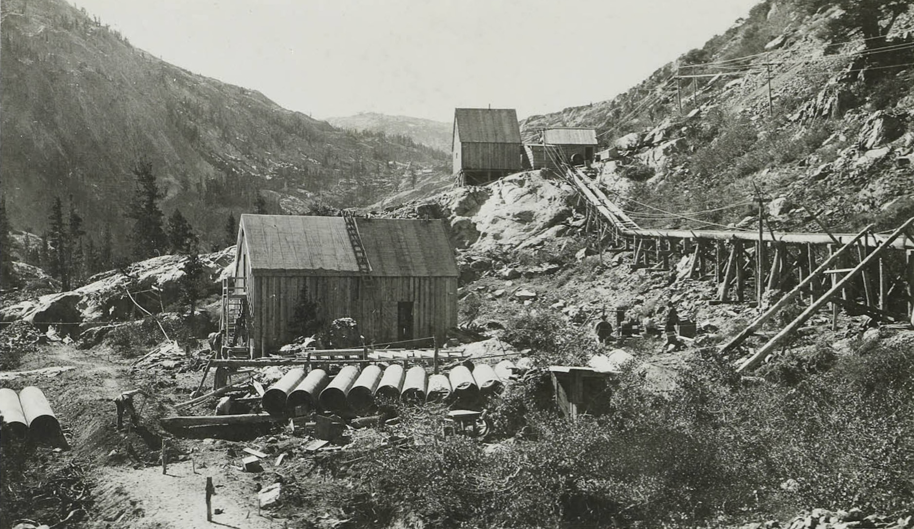
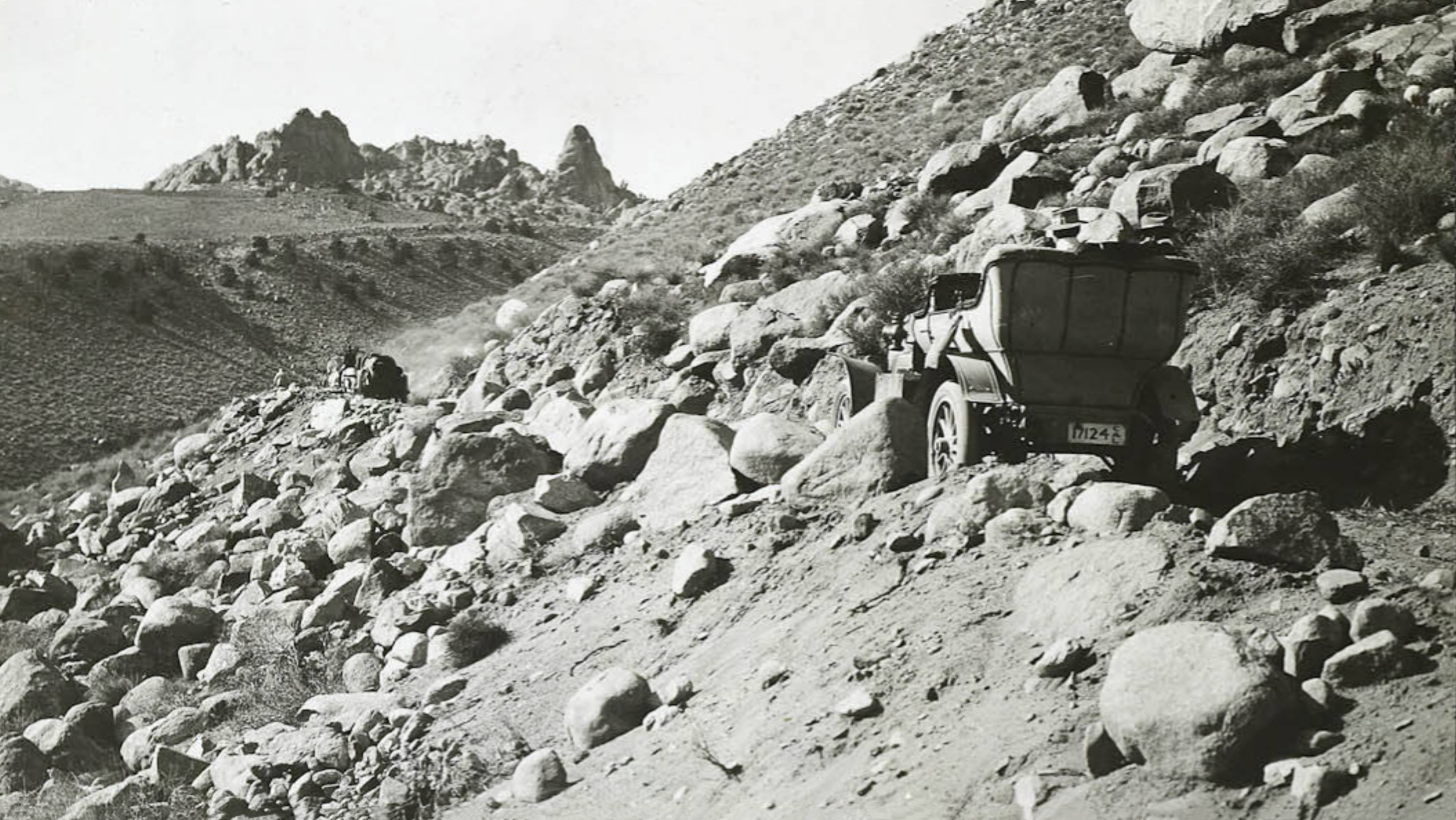
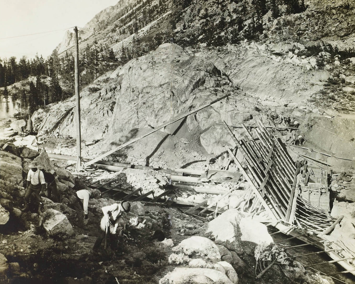
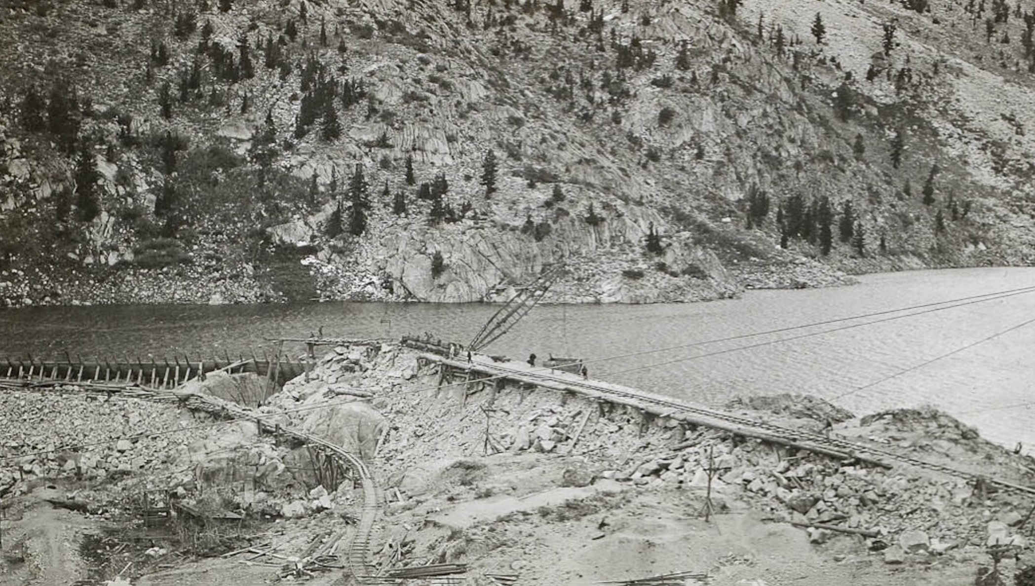
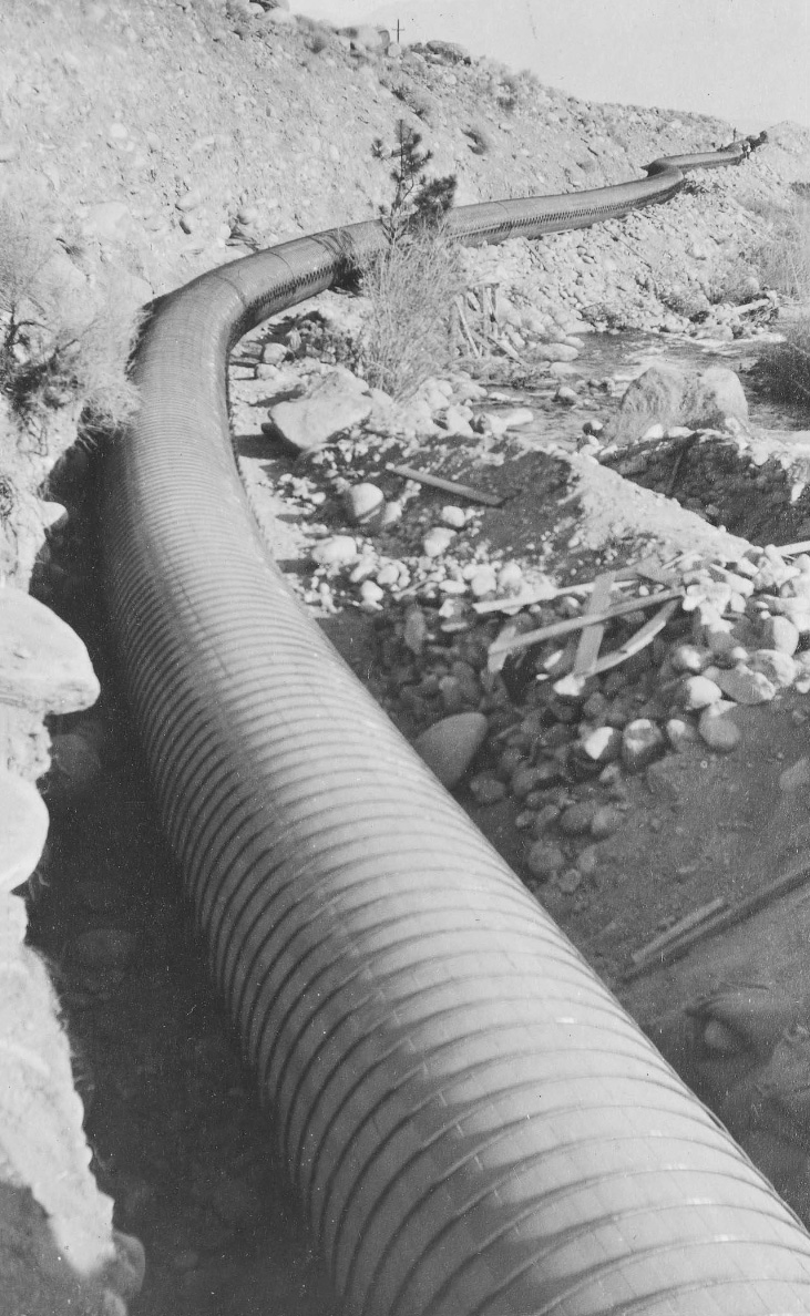
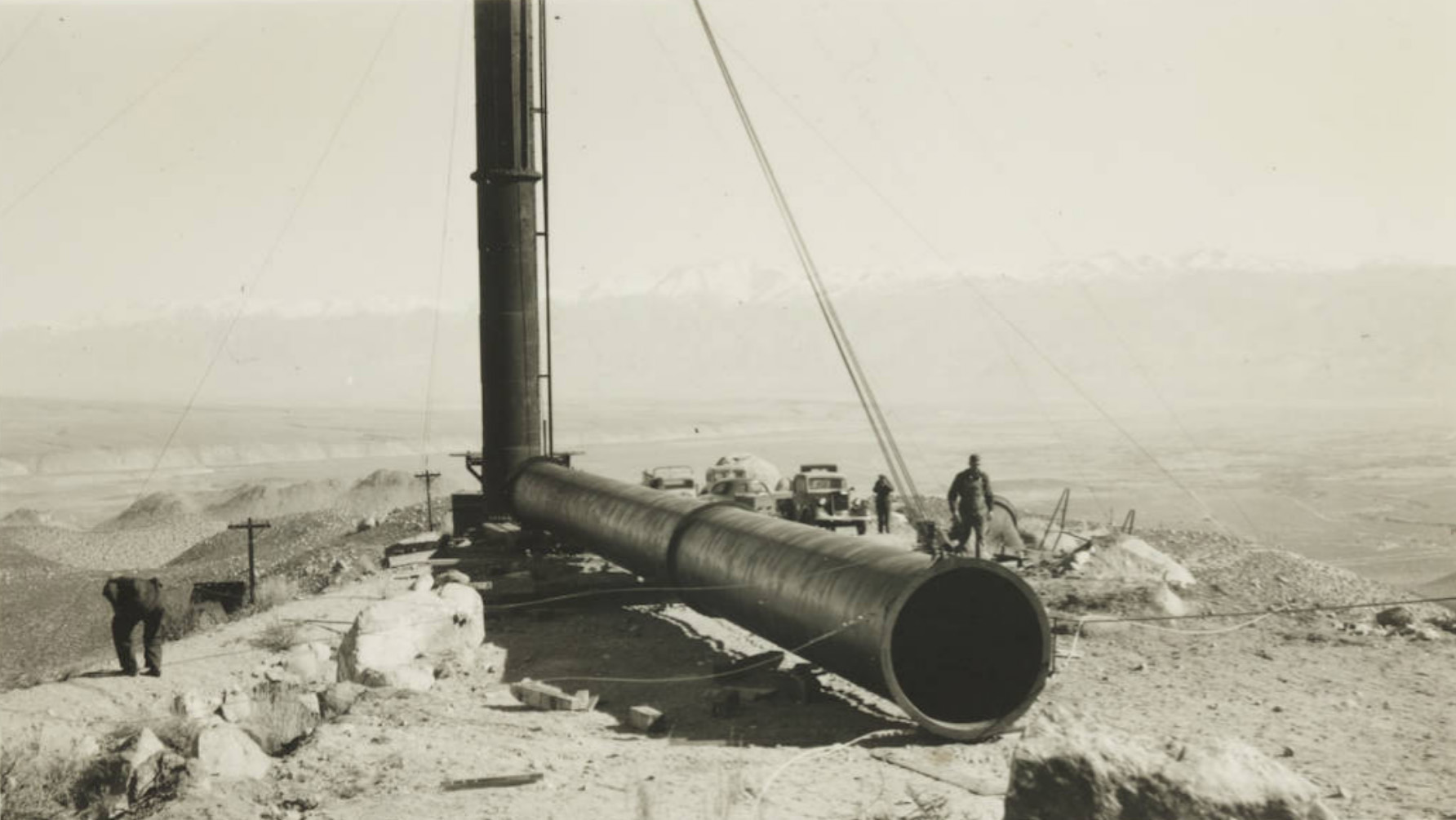
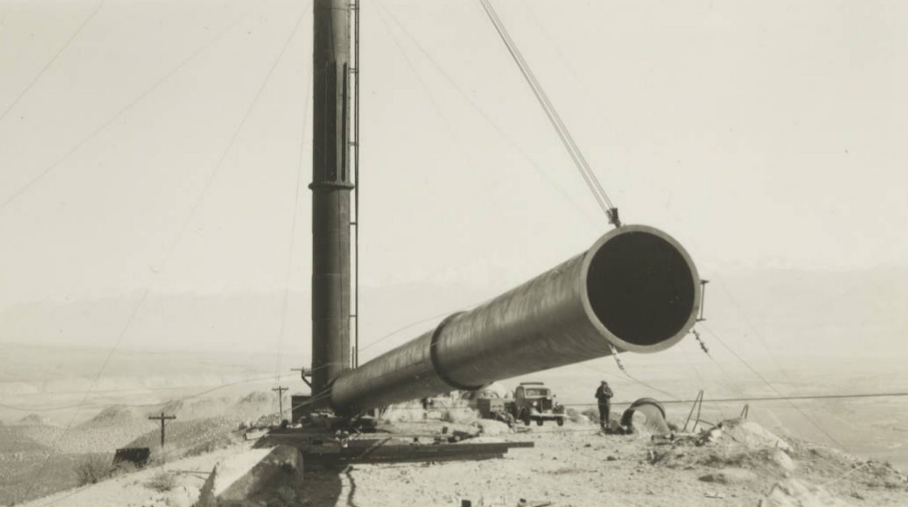
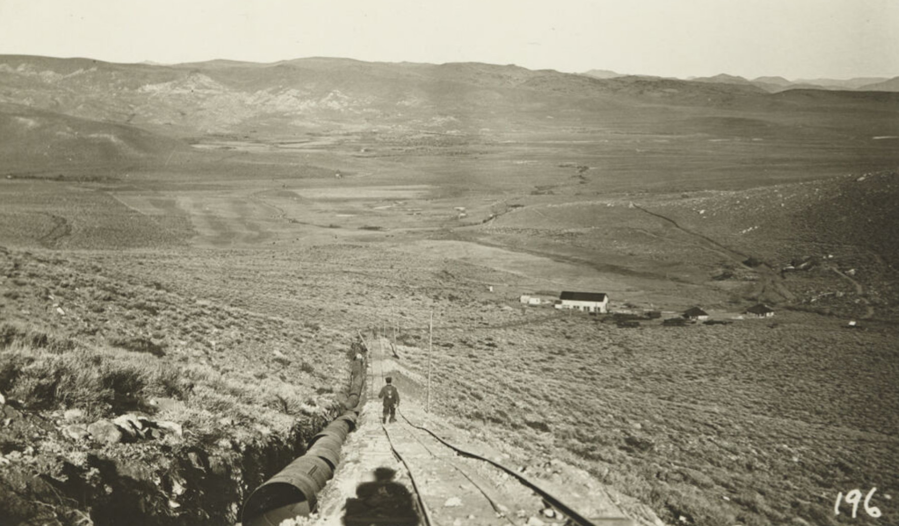 Looking down the steel pipe towards the powerhouse - halfway up the hill near Copper Mountain |
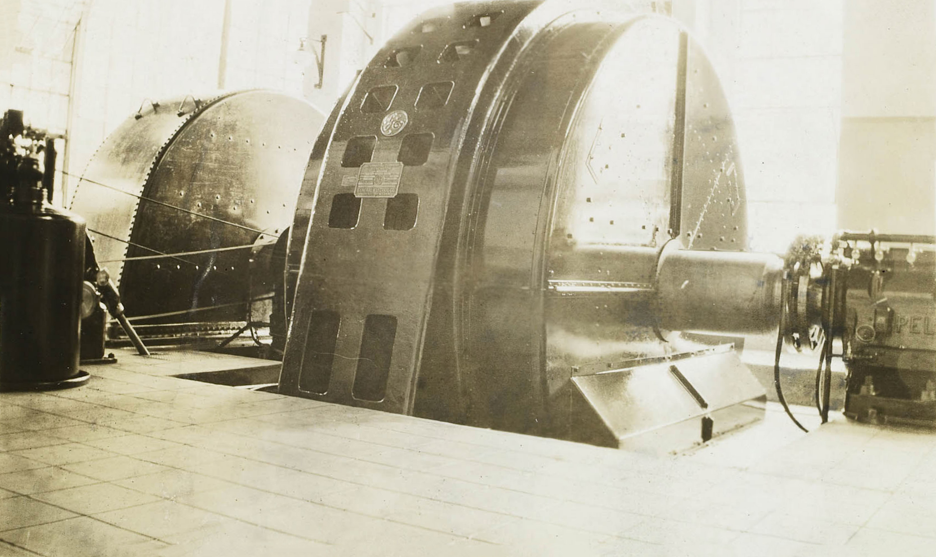
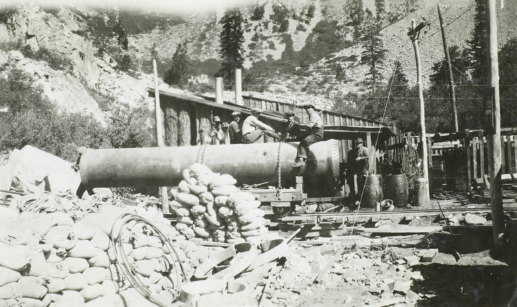
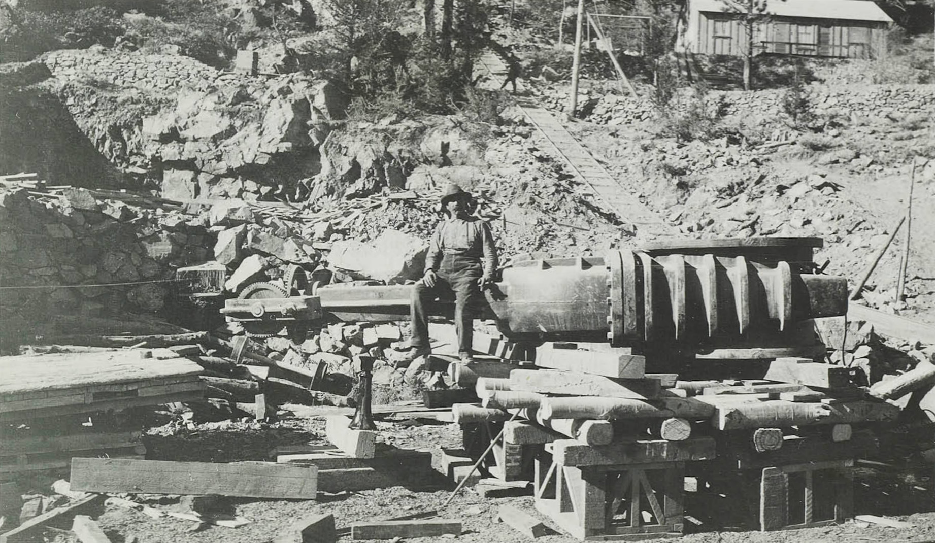
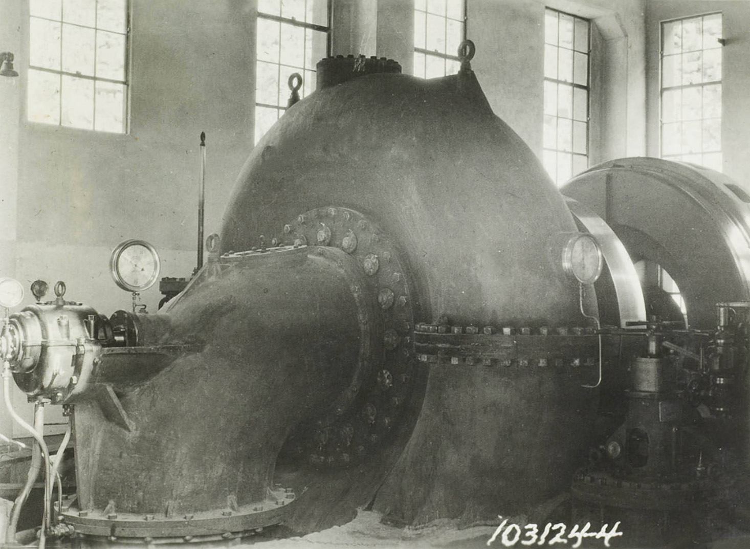
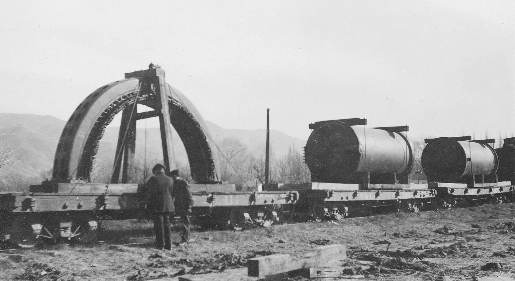
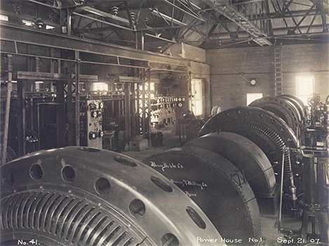
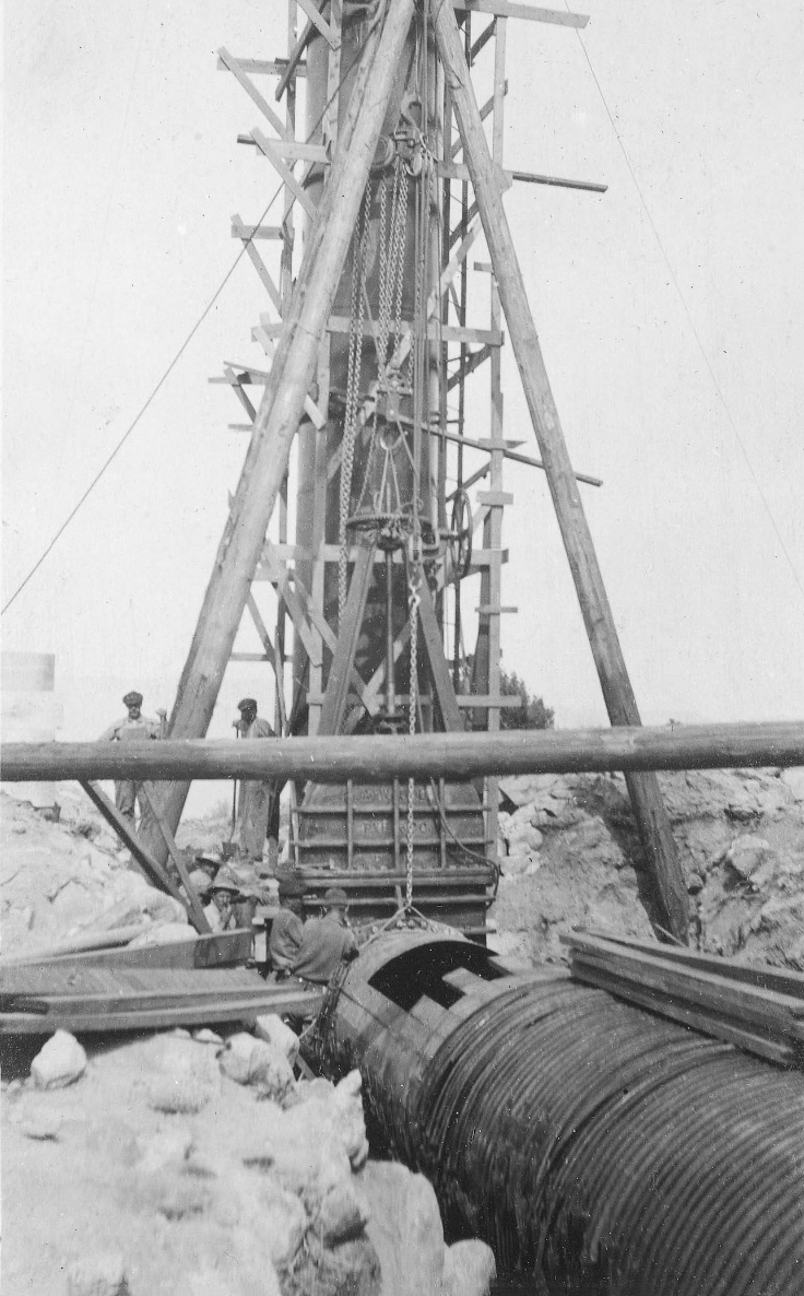
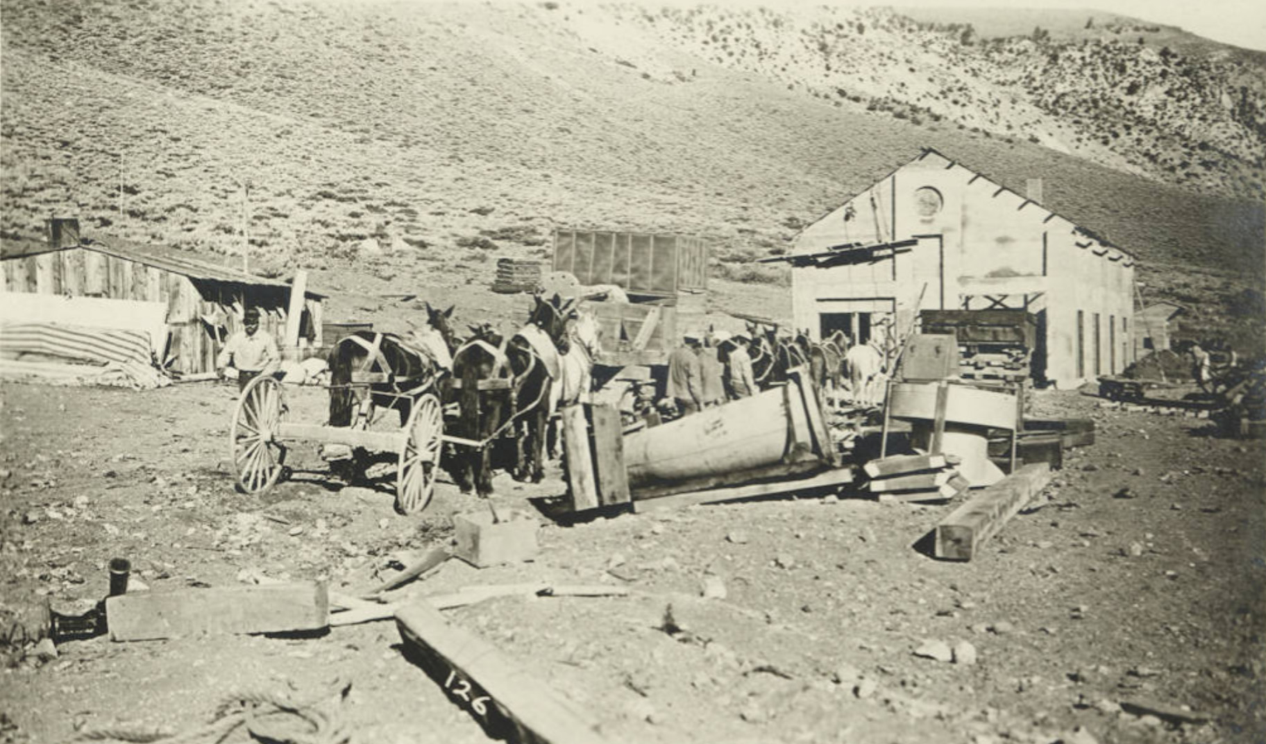 Arrival of the rotar a the powerhouse in 1910. |
|
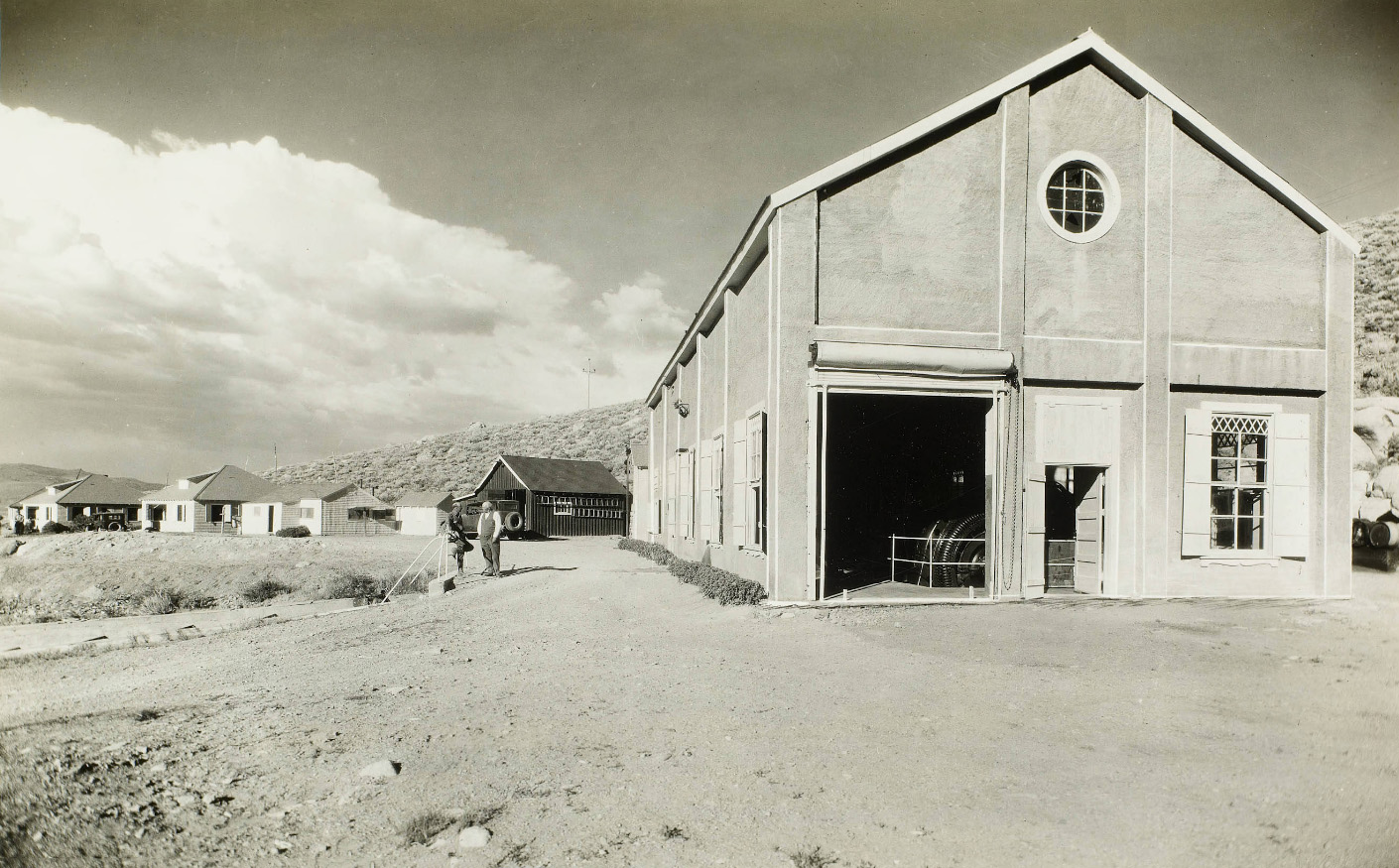
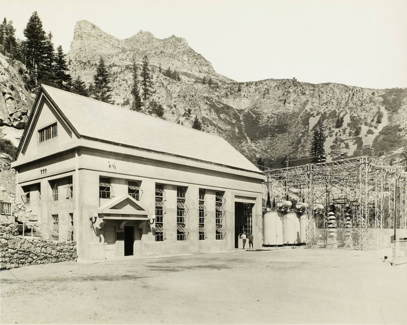
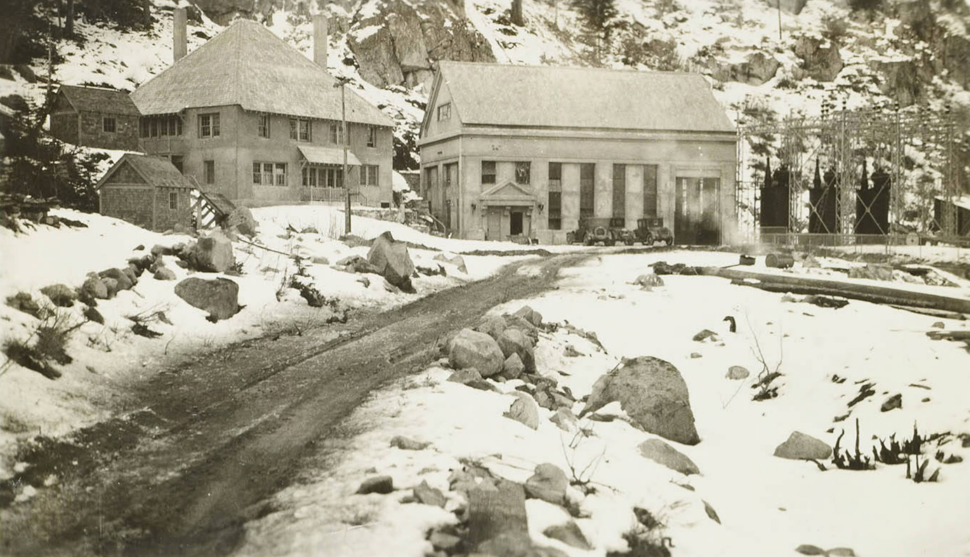
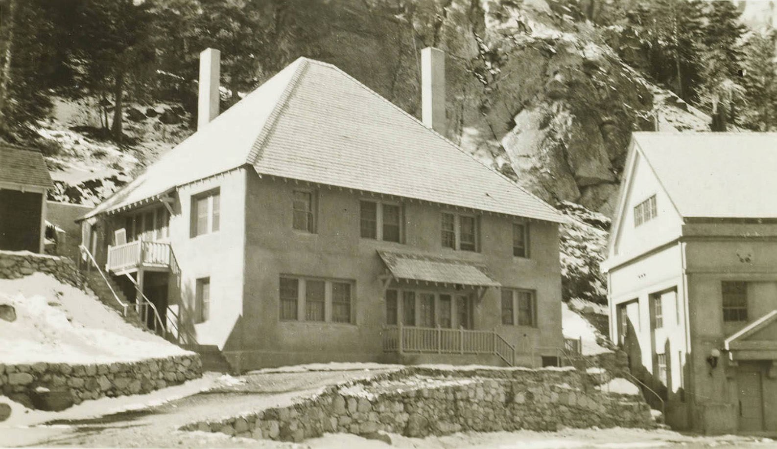
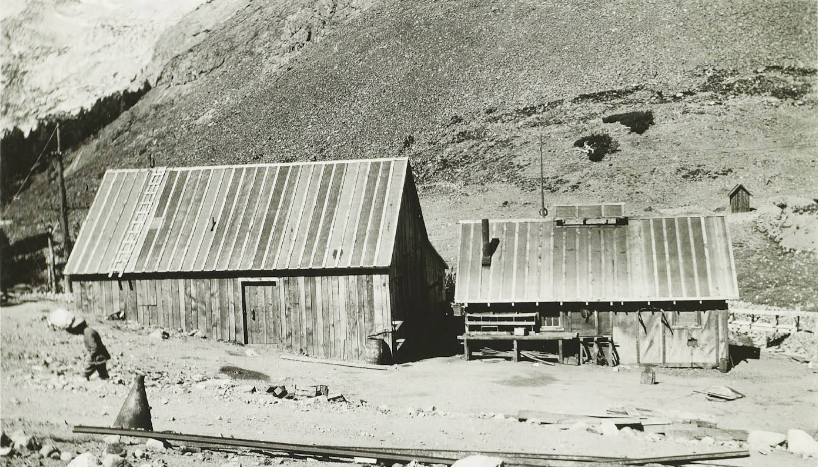
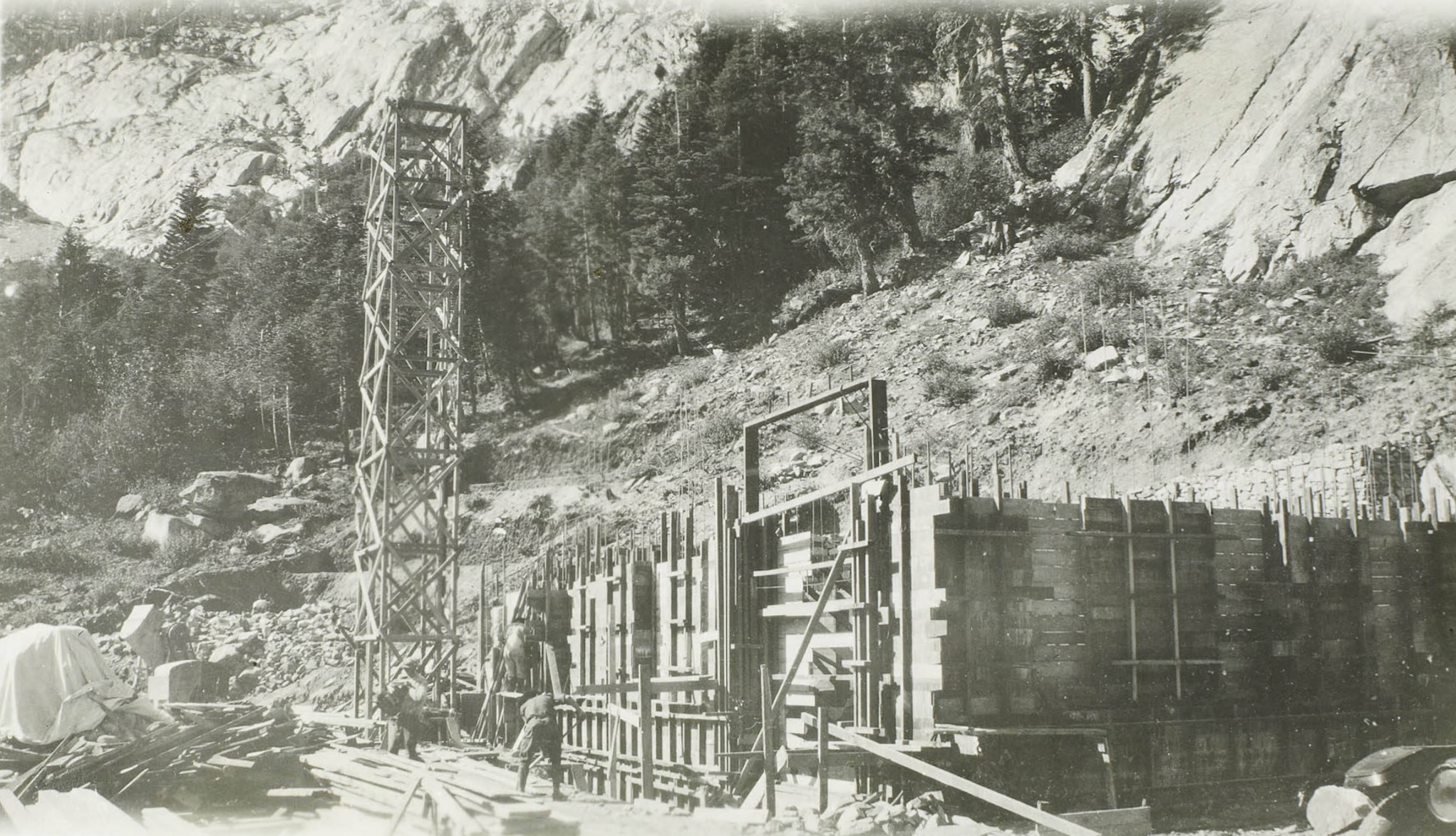
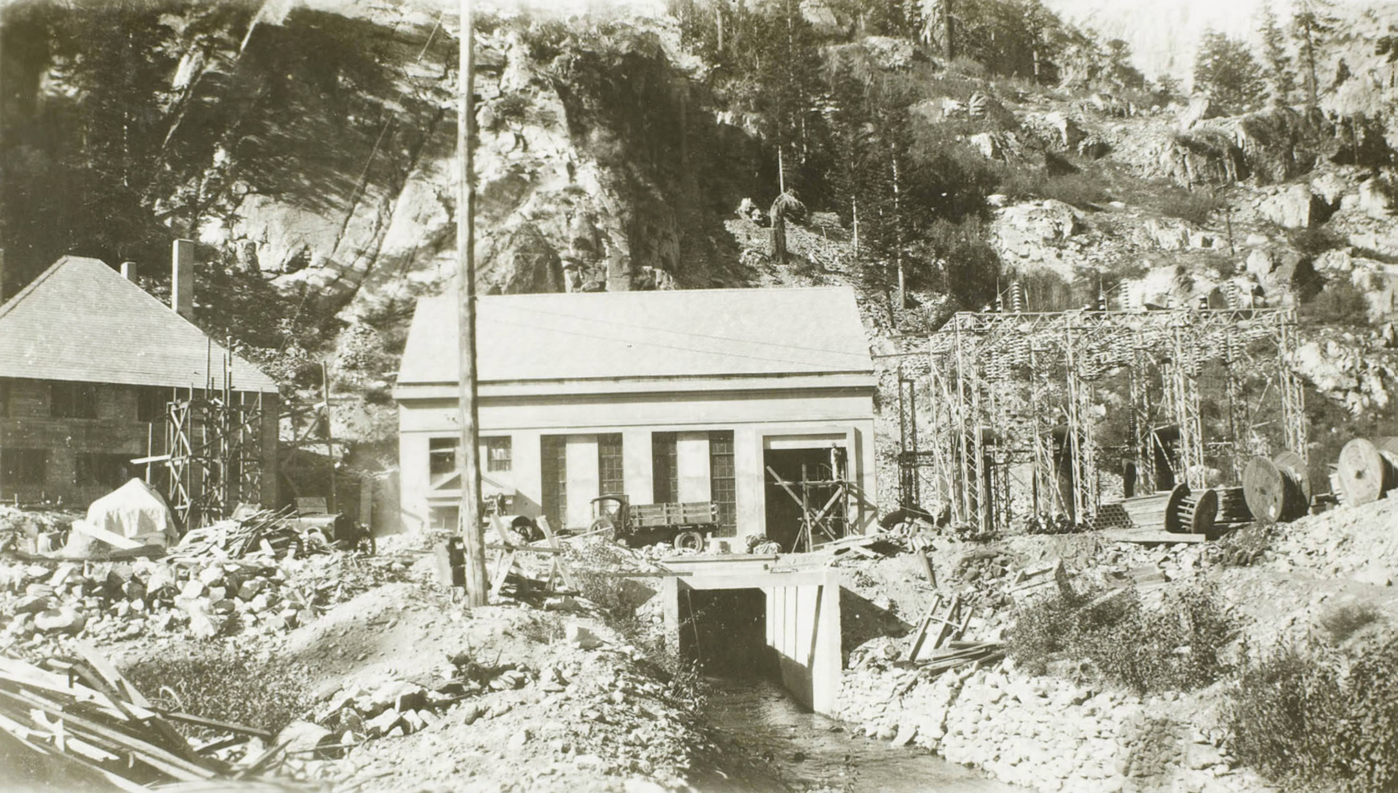
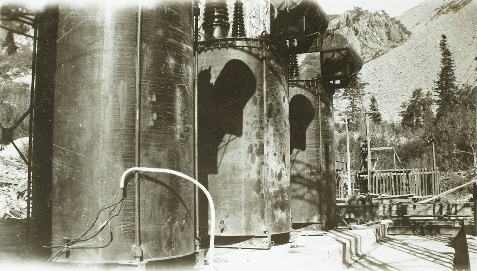
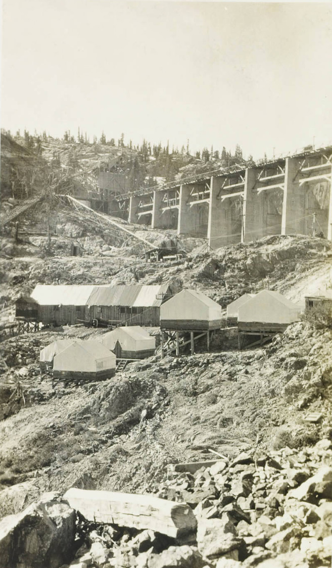
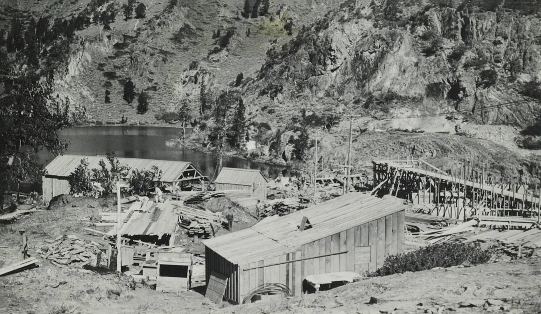
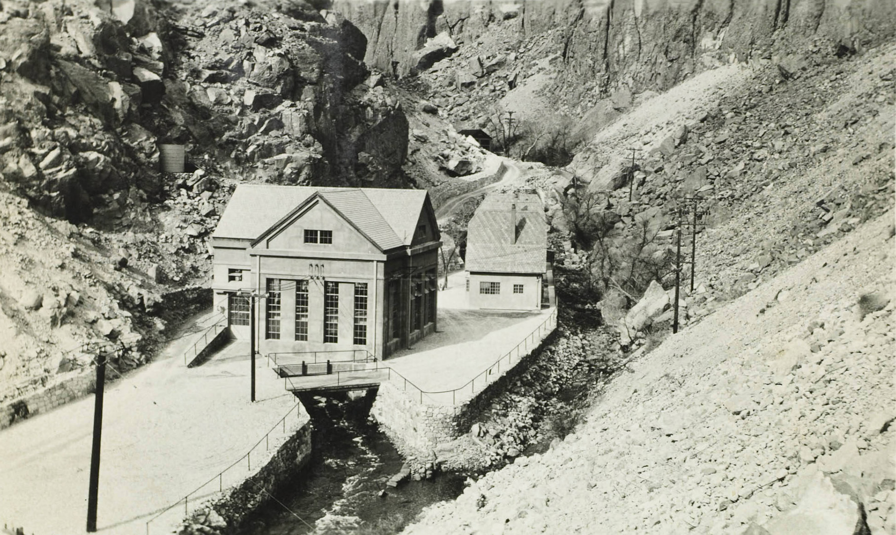
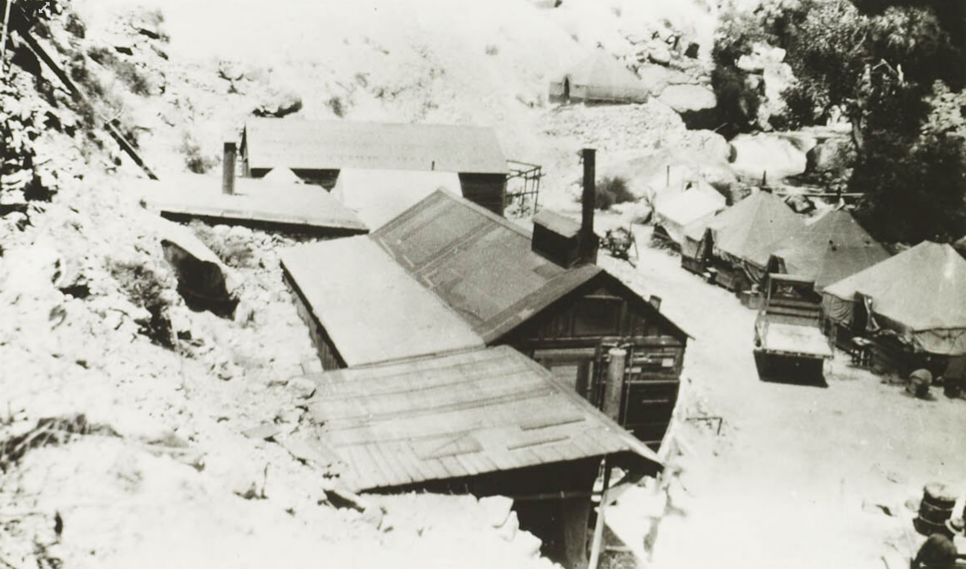
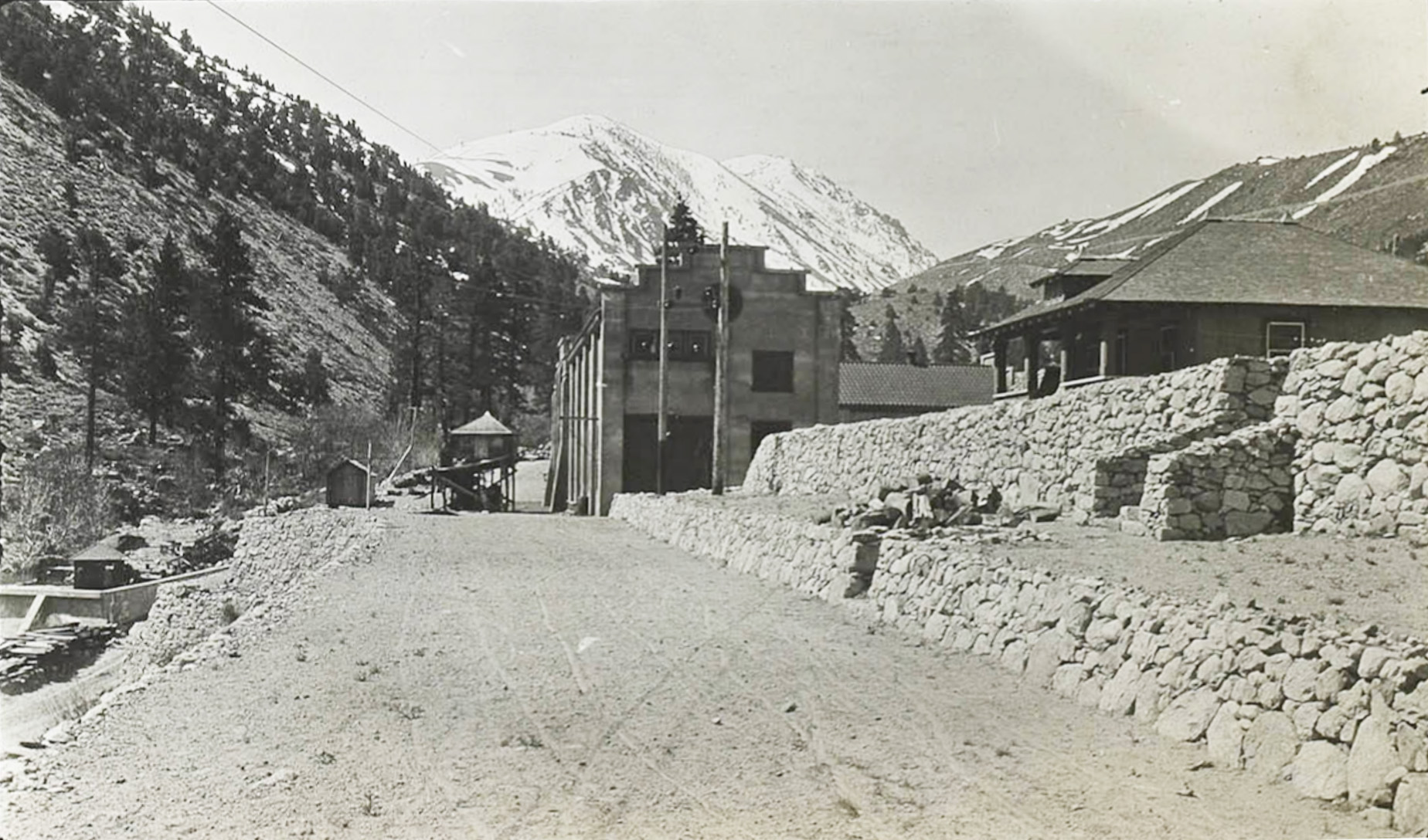
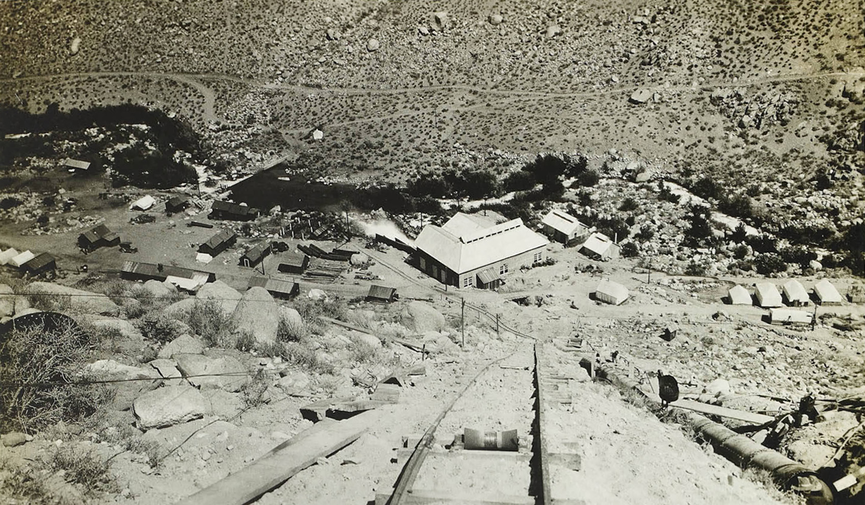
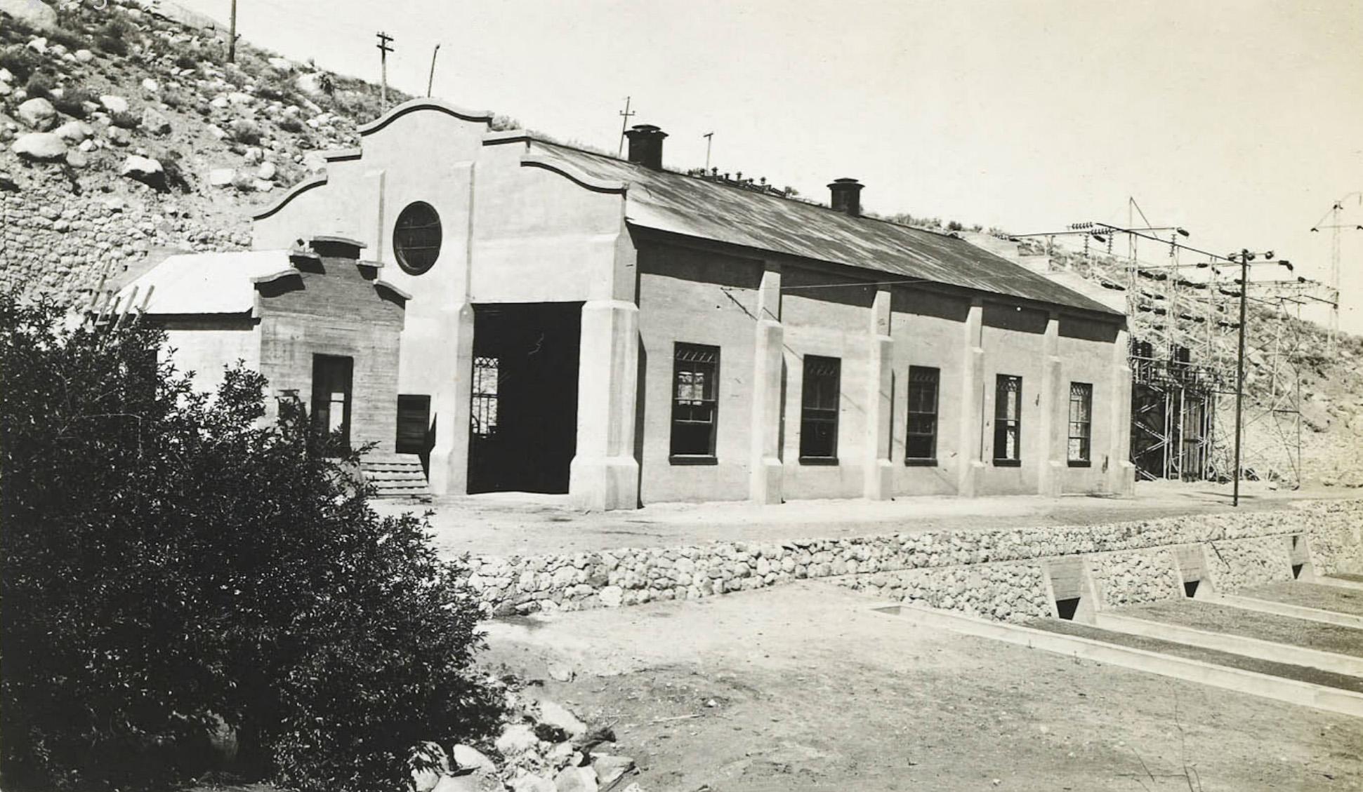
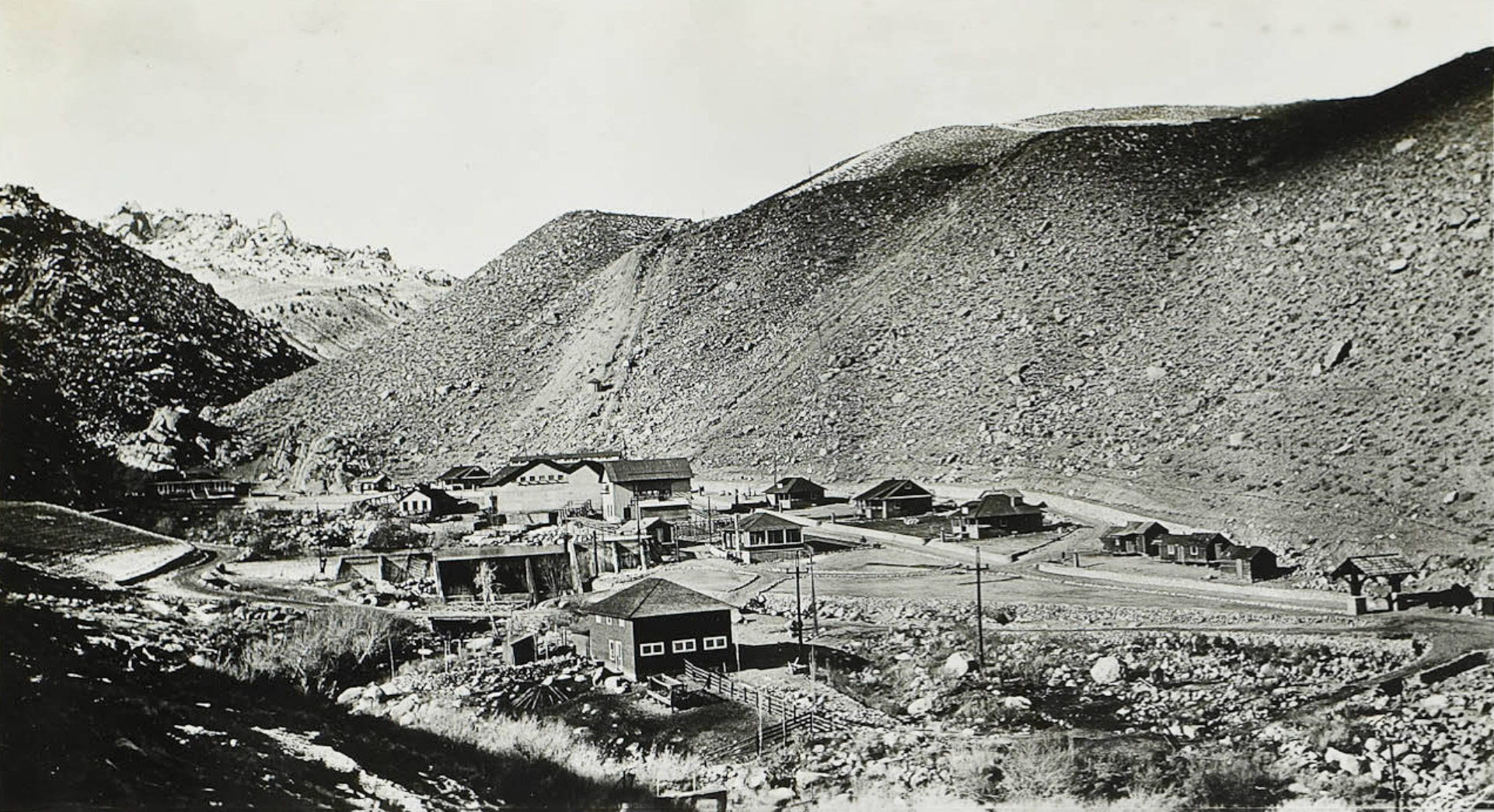
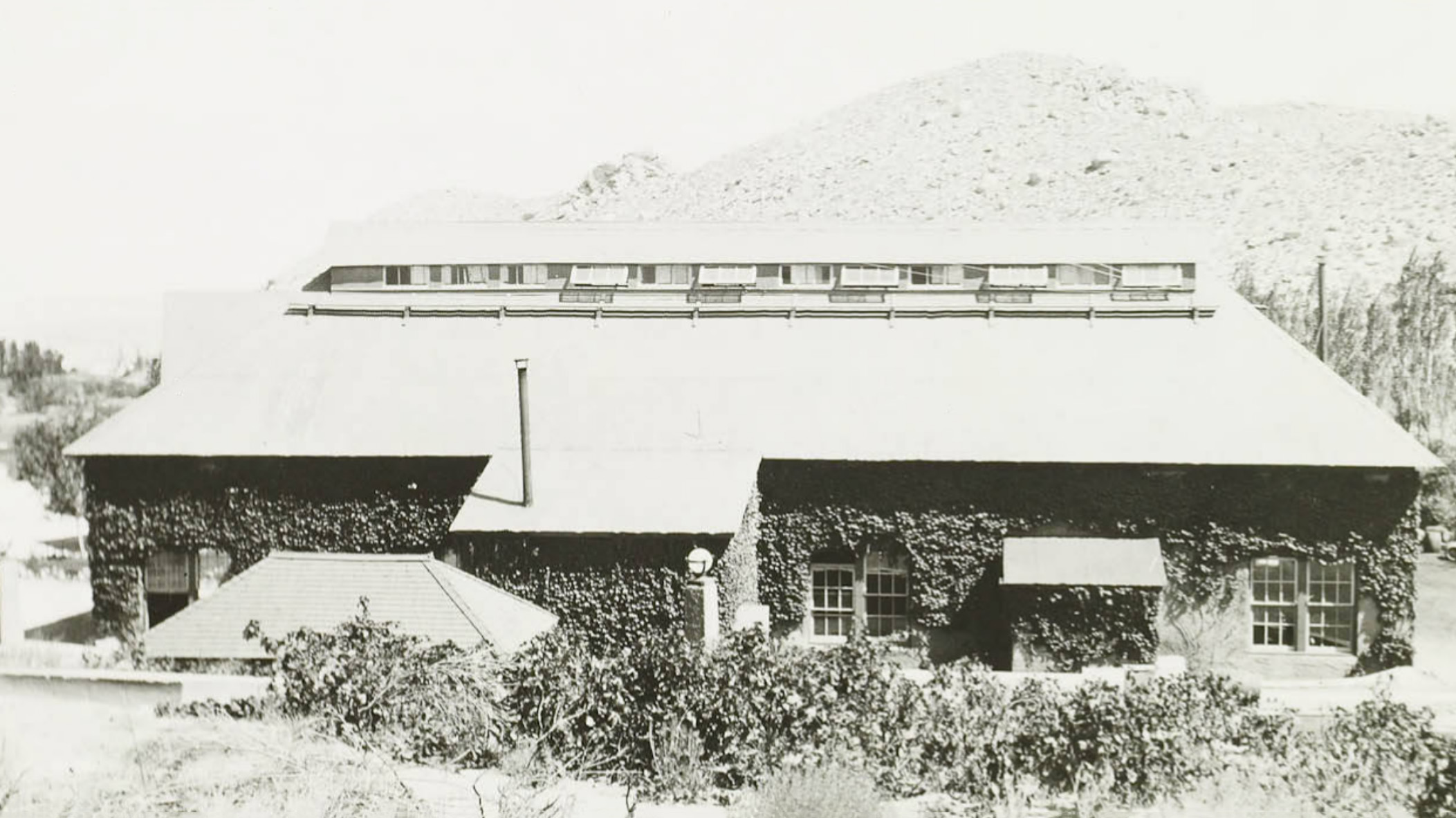
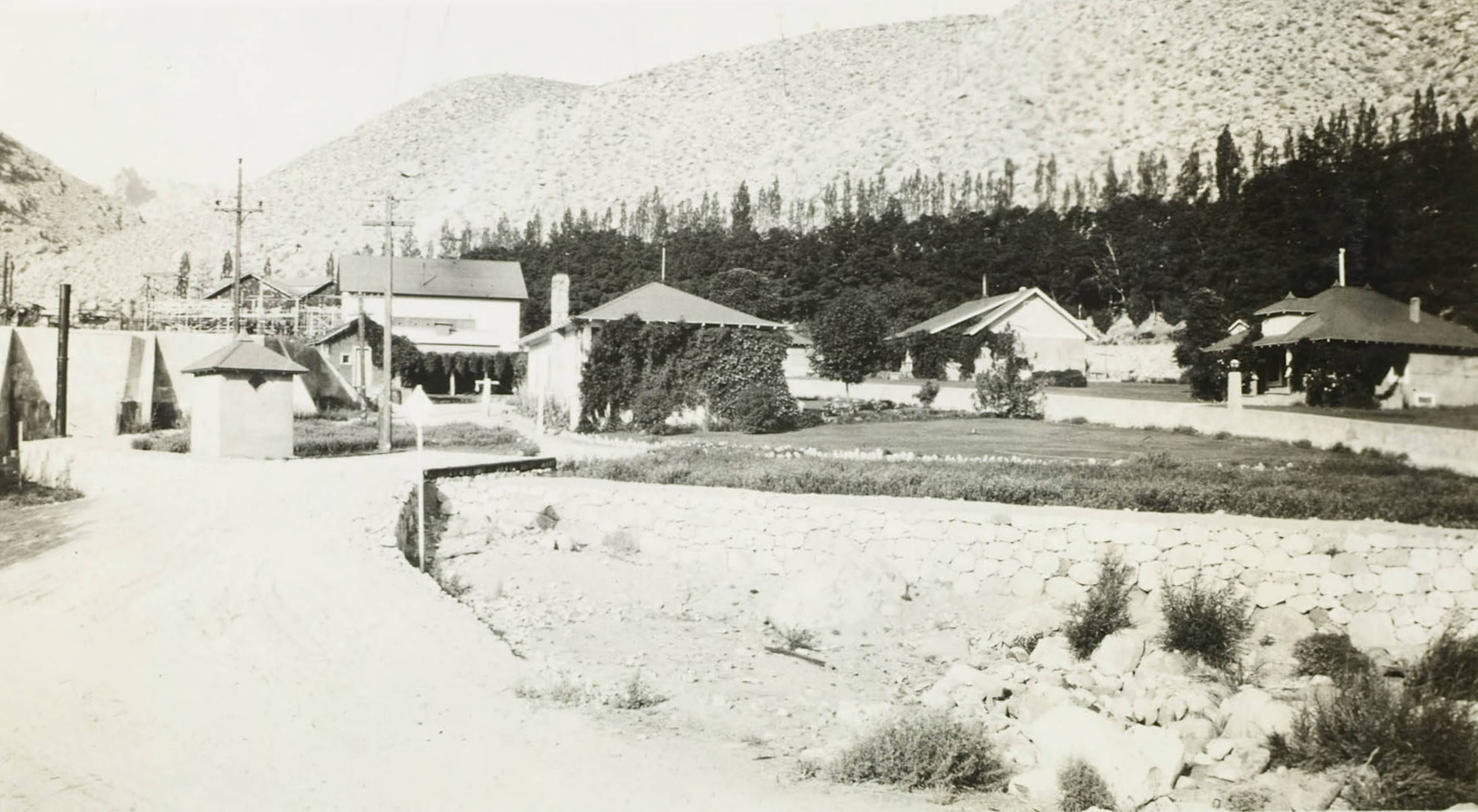
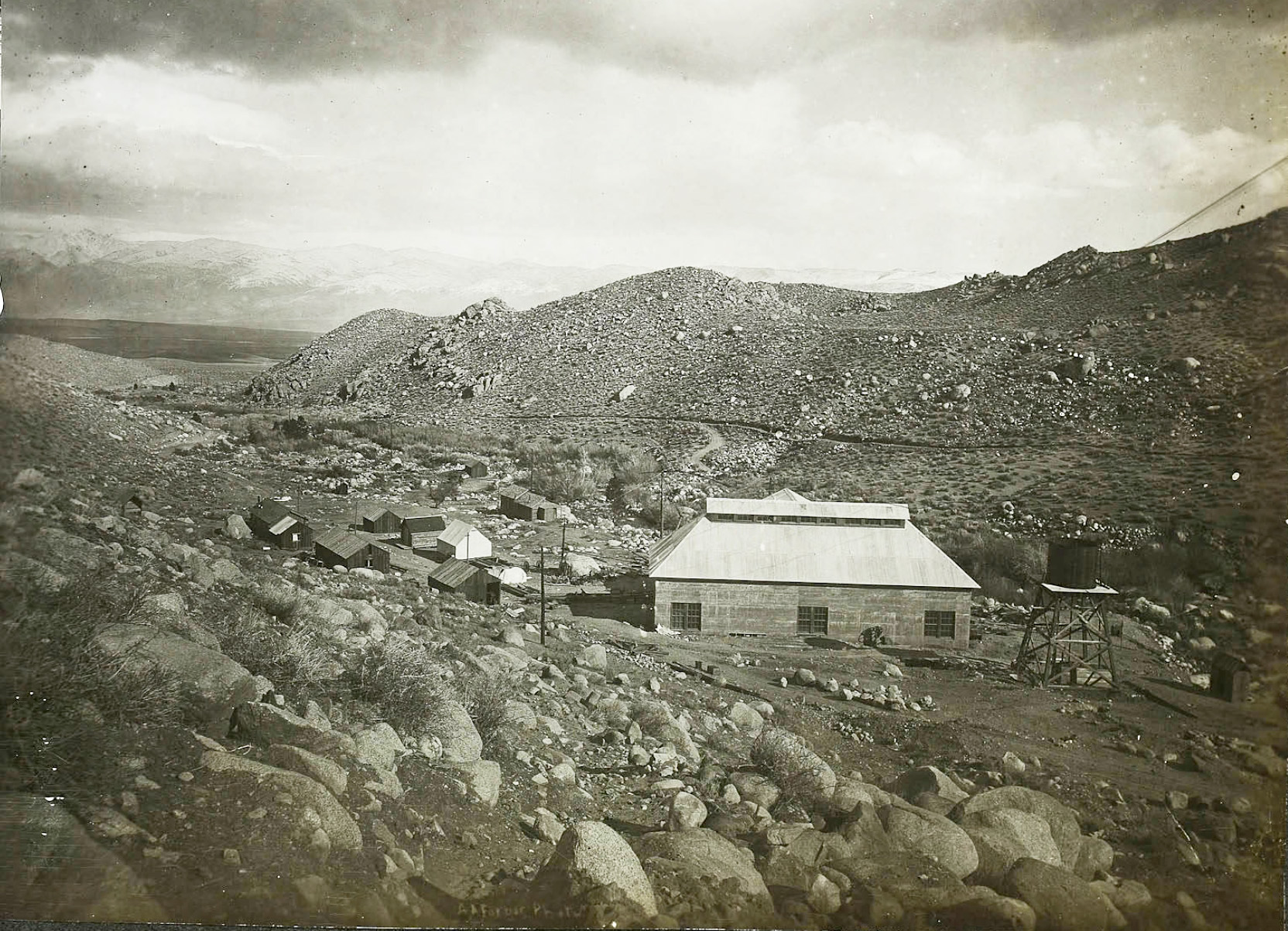
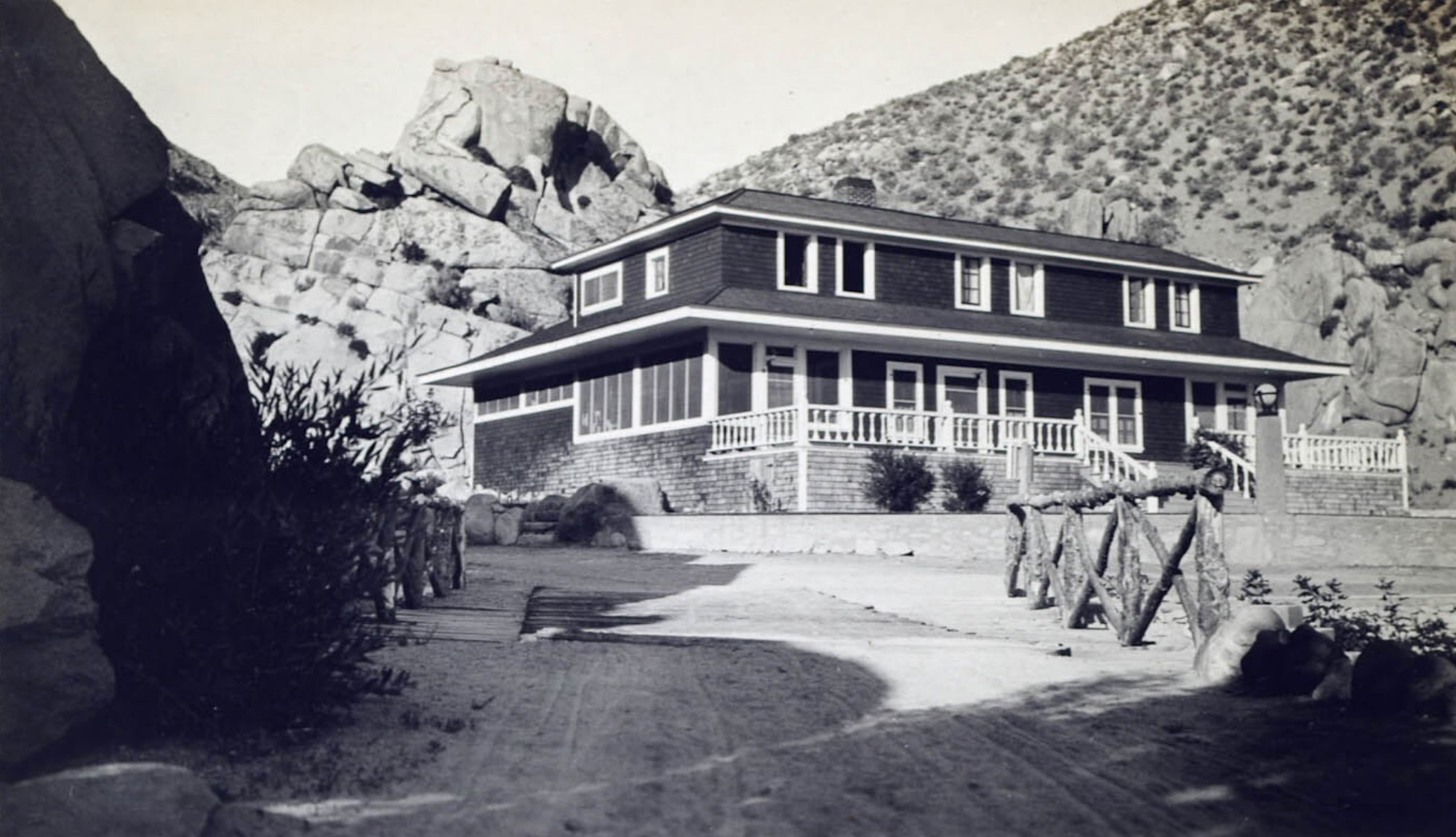
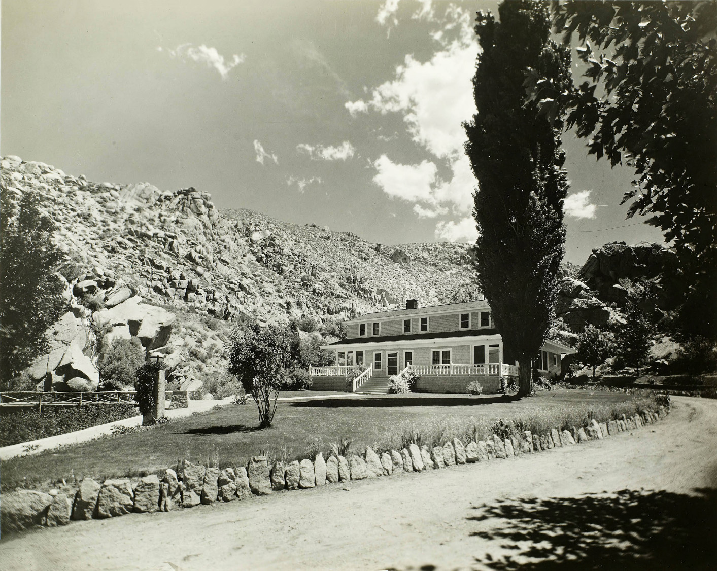
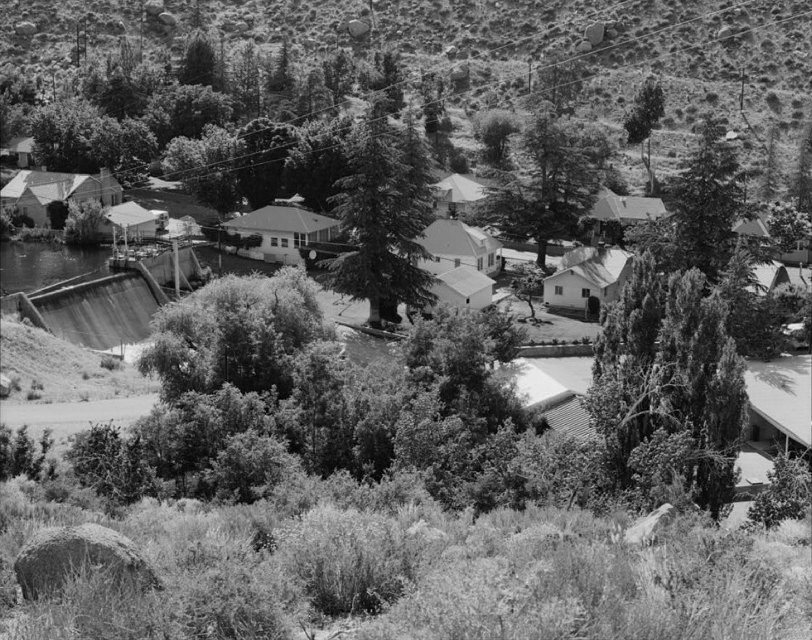
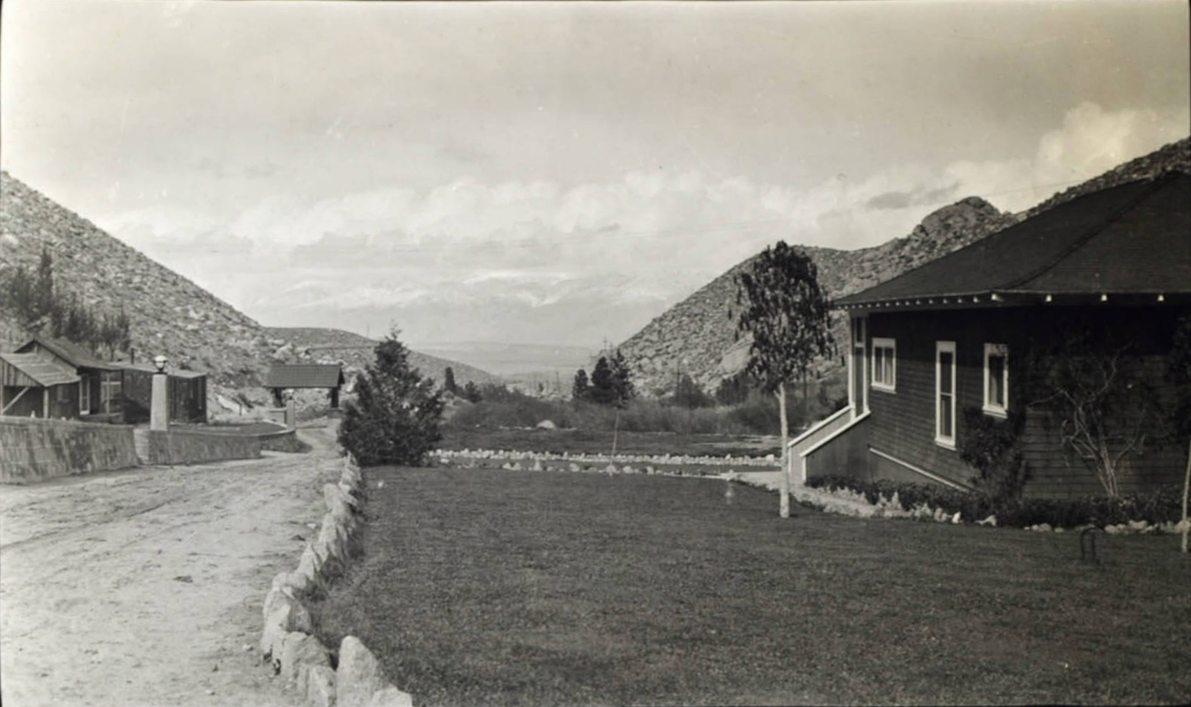
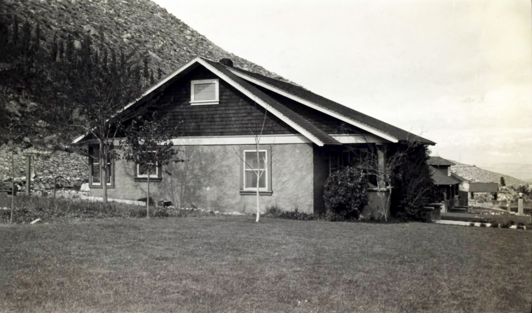
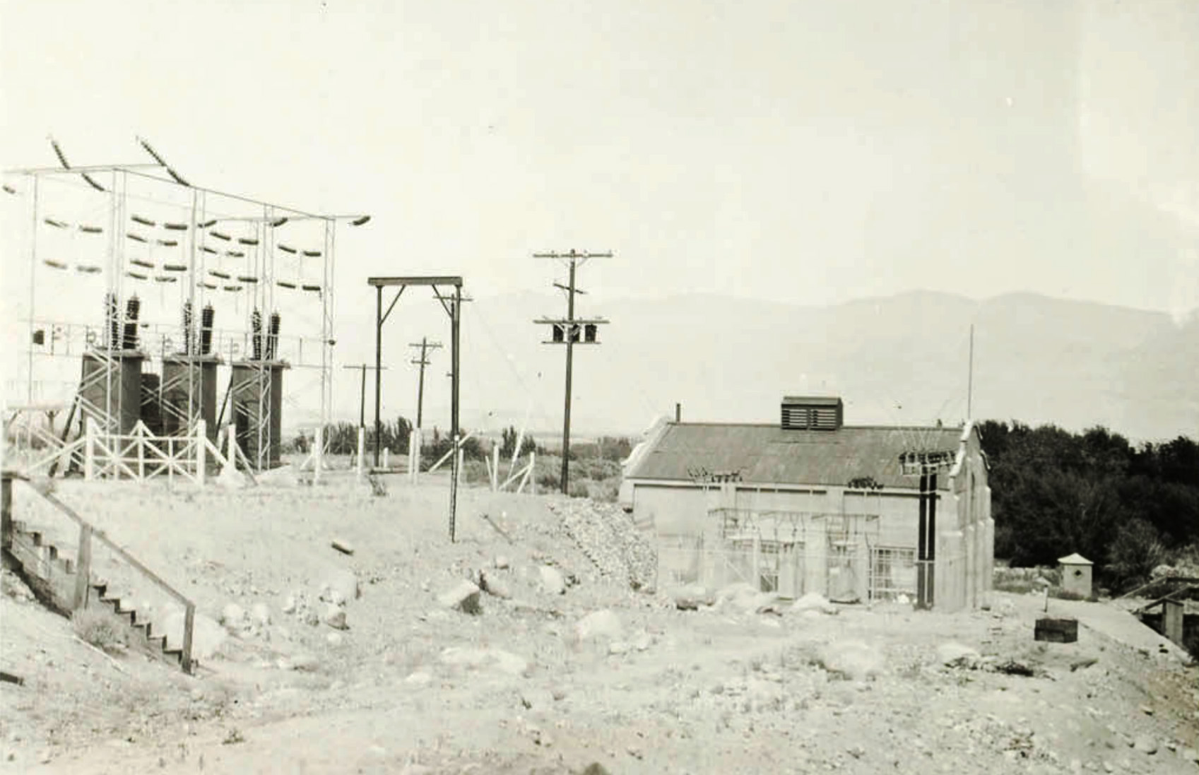
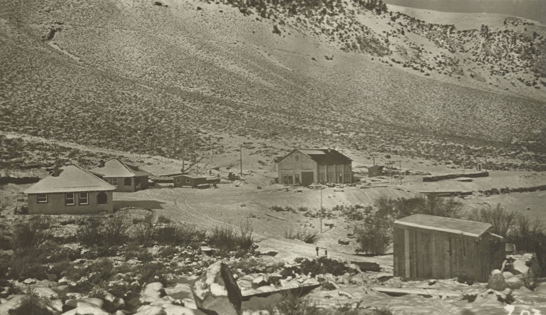 Powerhouse grounds - Jordan (Mill Creek) Plant |
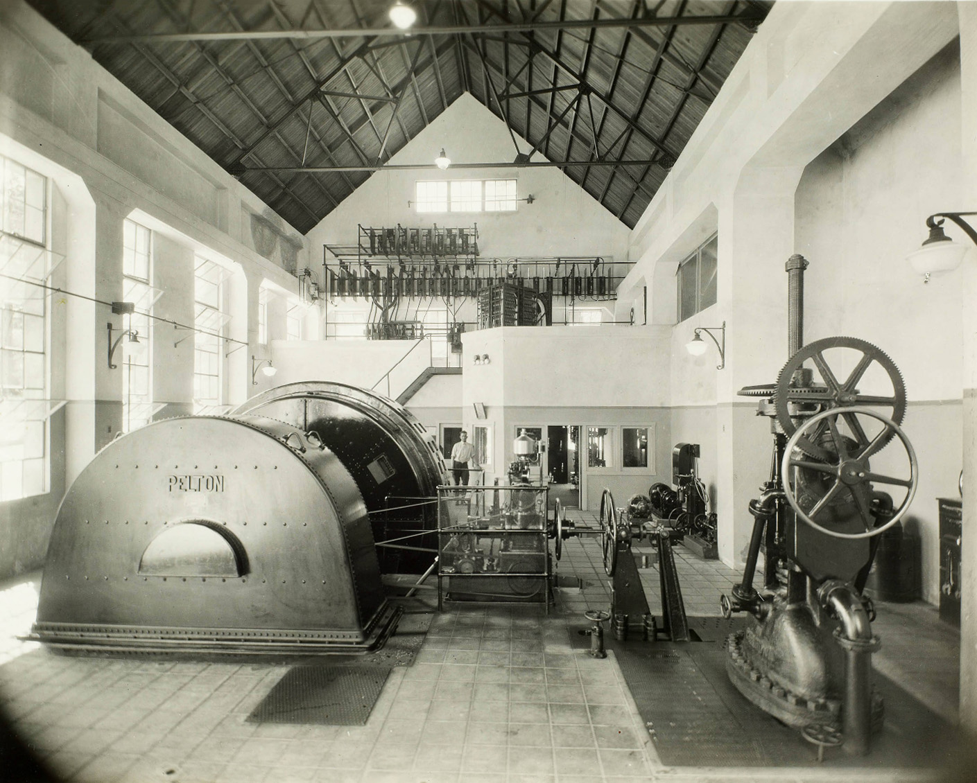
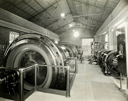
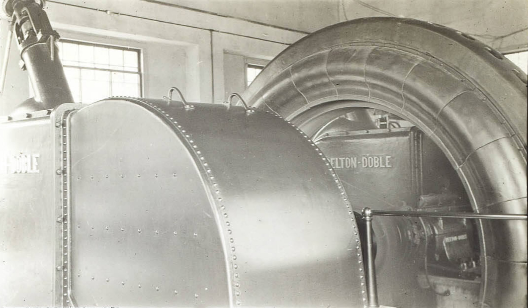
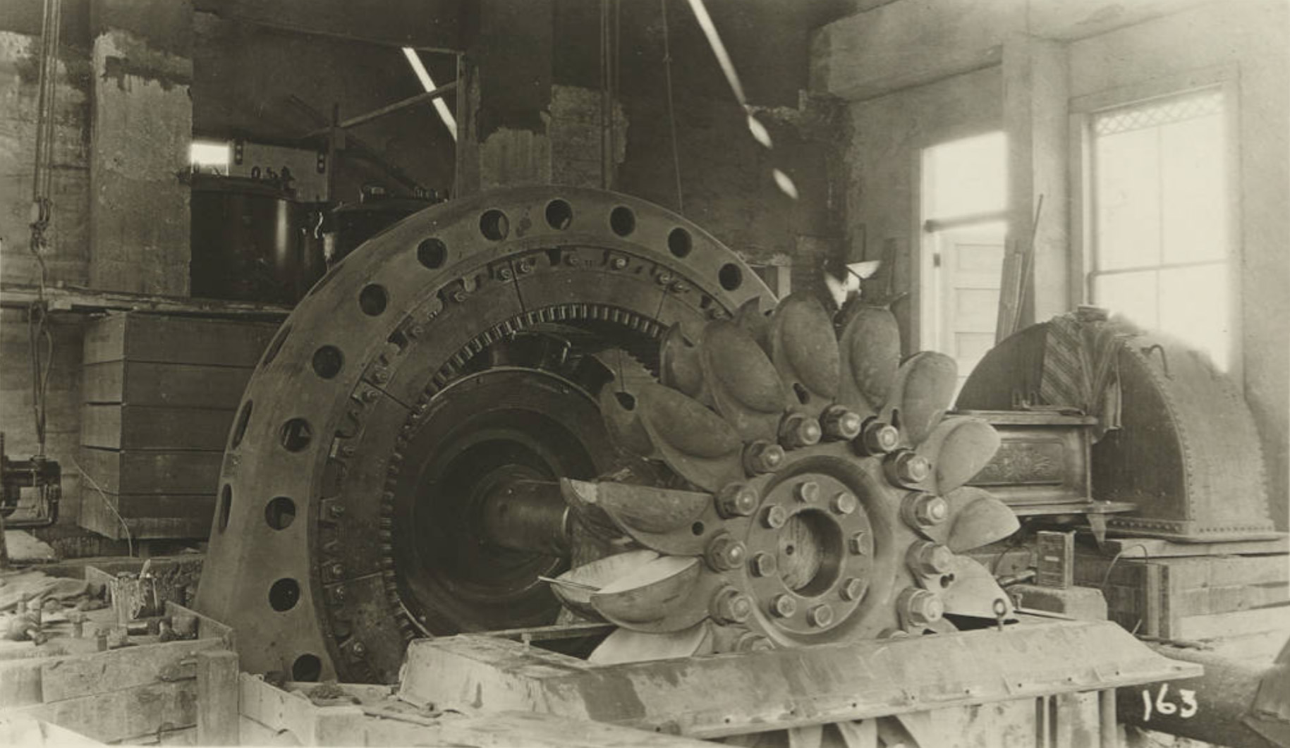 No. 1 Unit - Jordan (Mill Creek) Plant 1 |
|
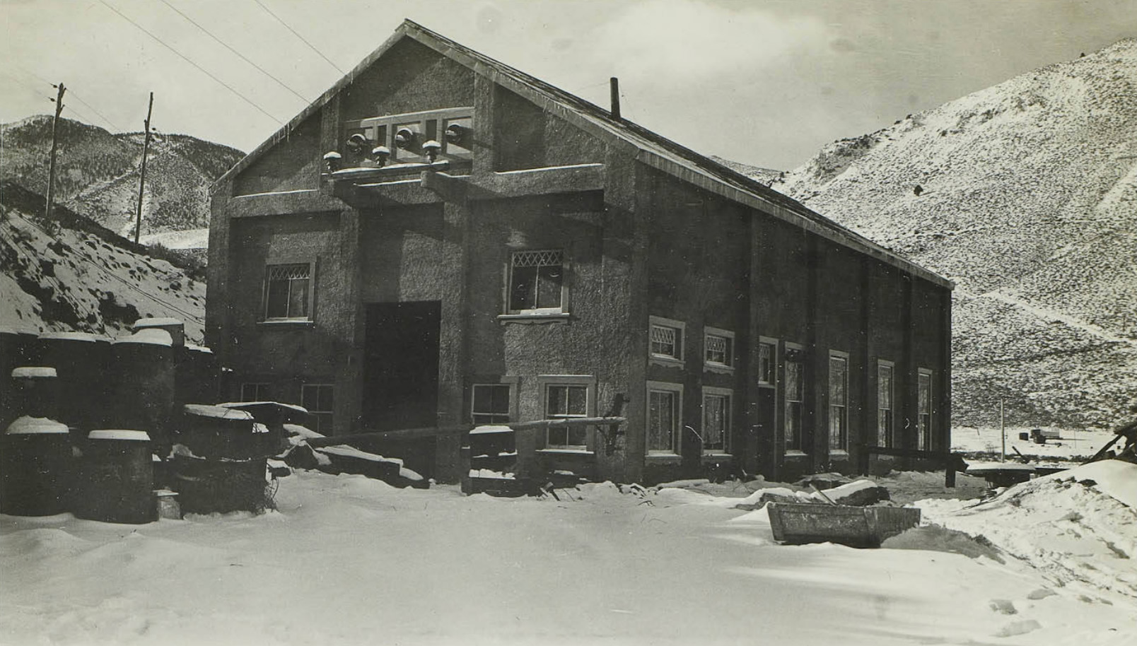
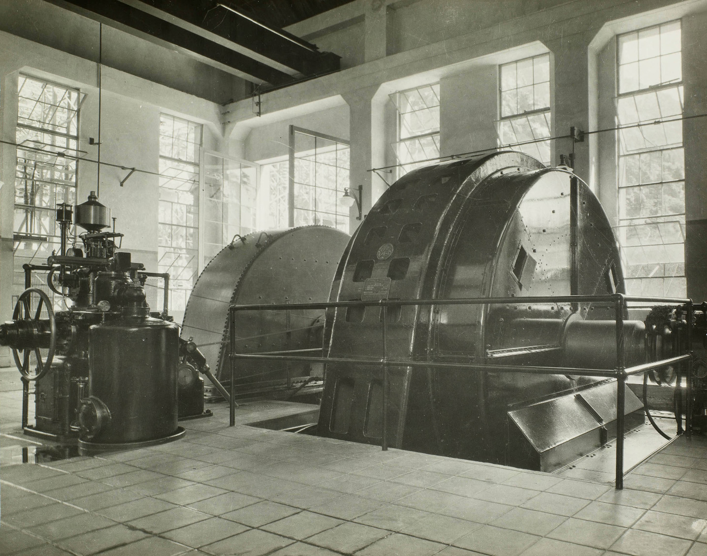
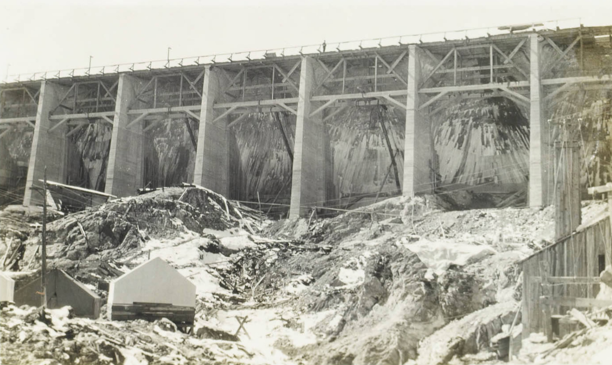
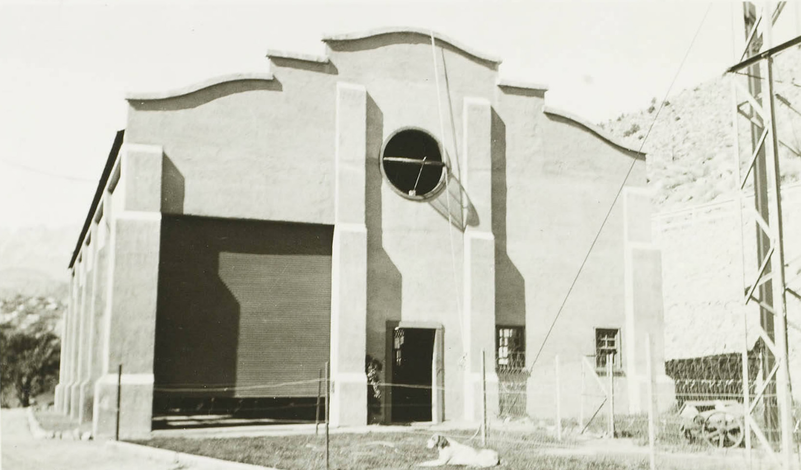
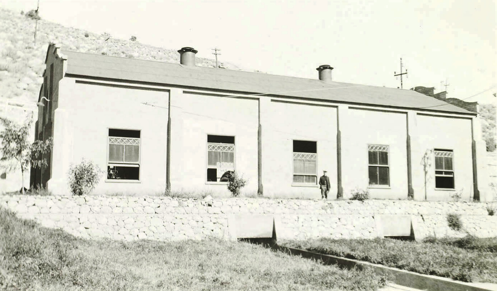
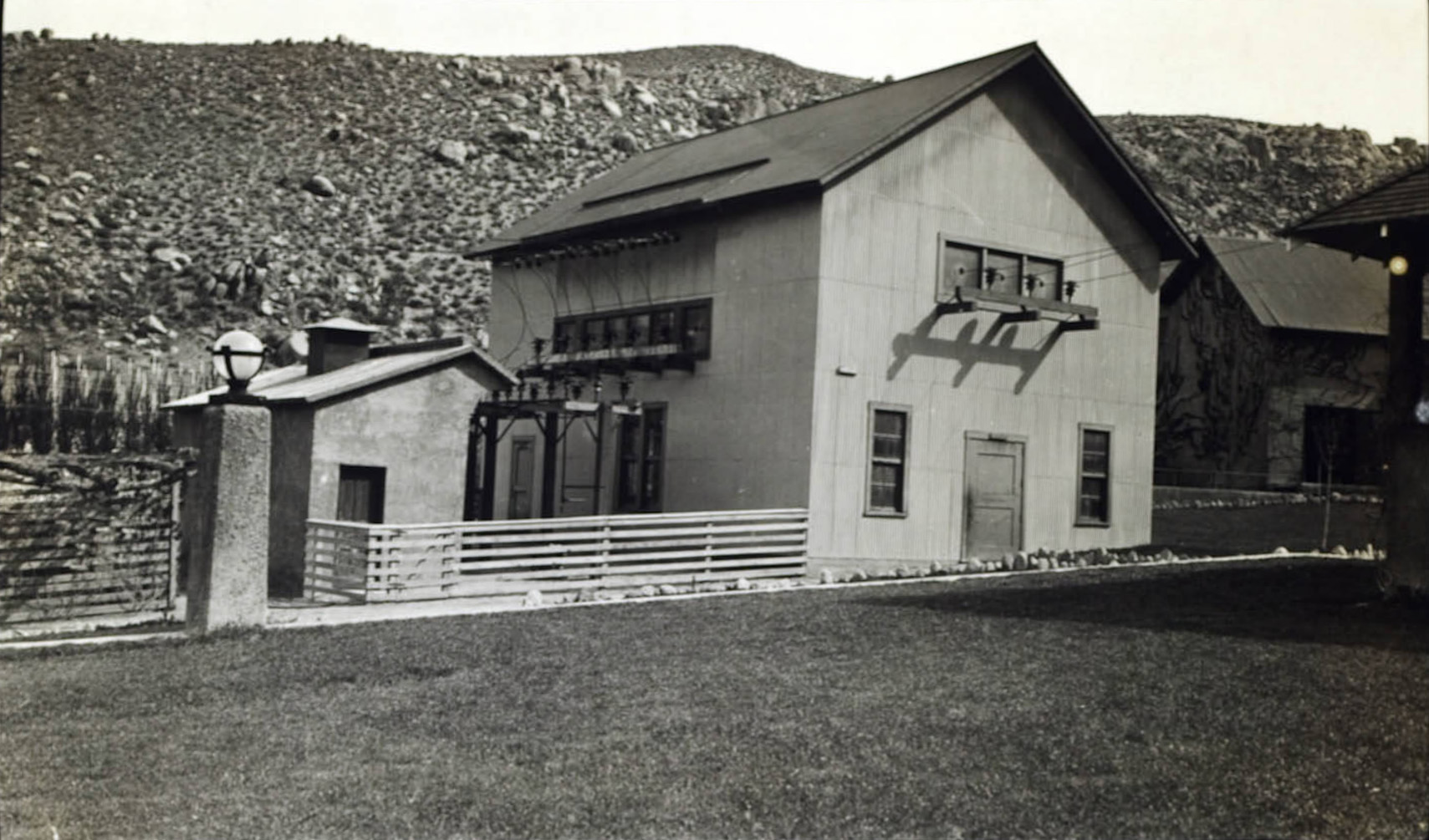
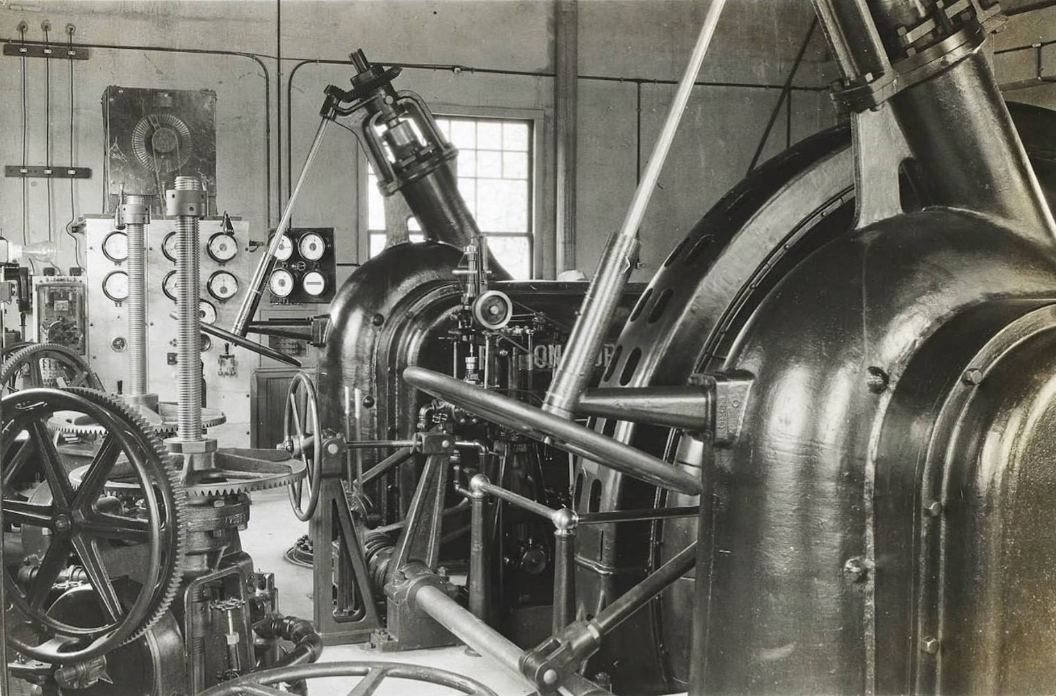
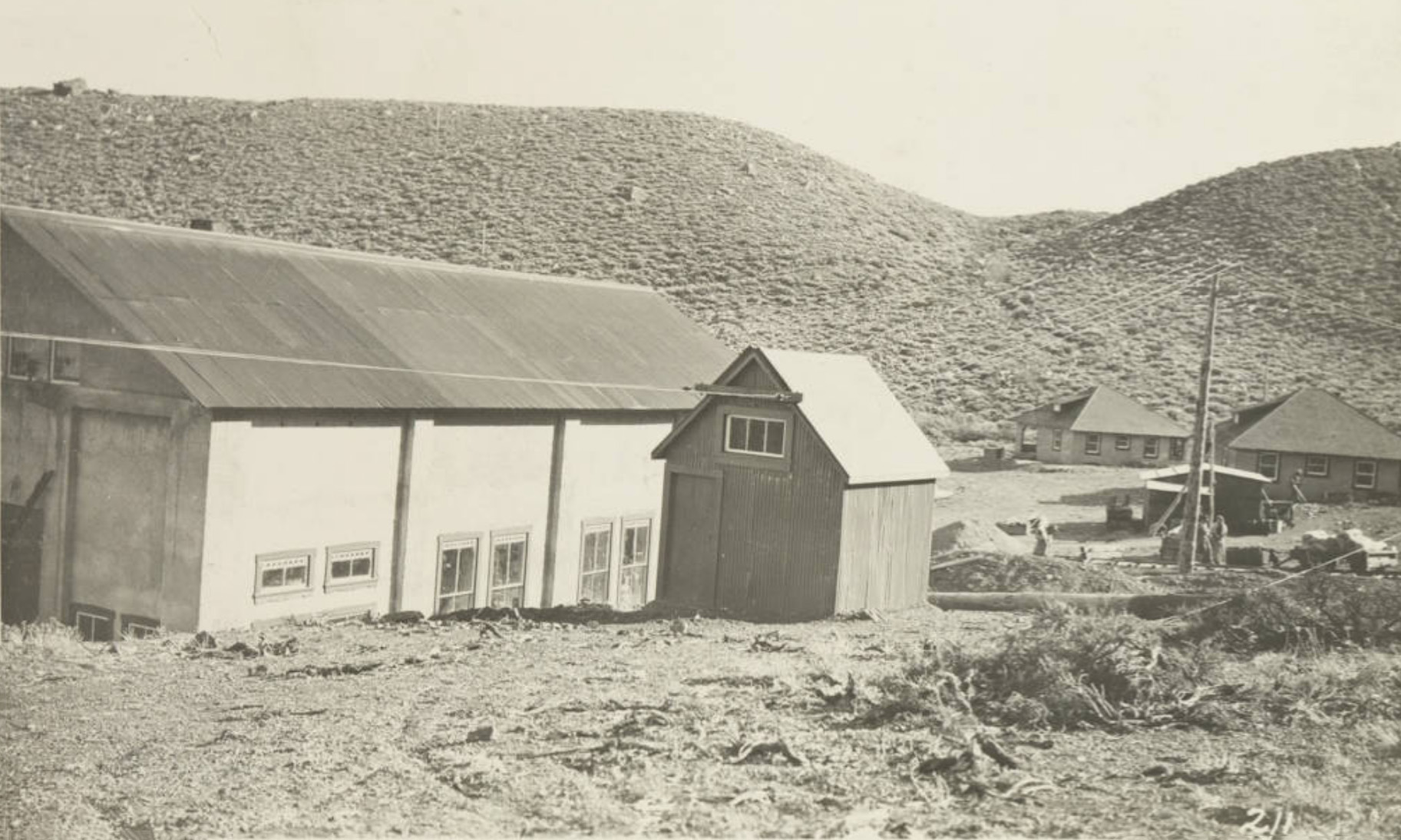 Rear view of the powerhouse |
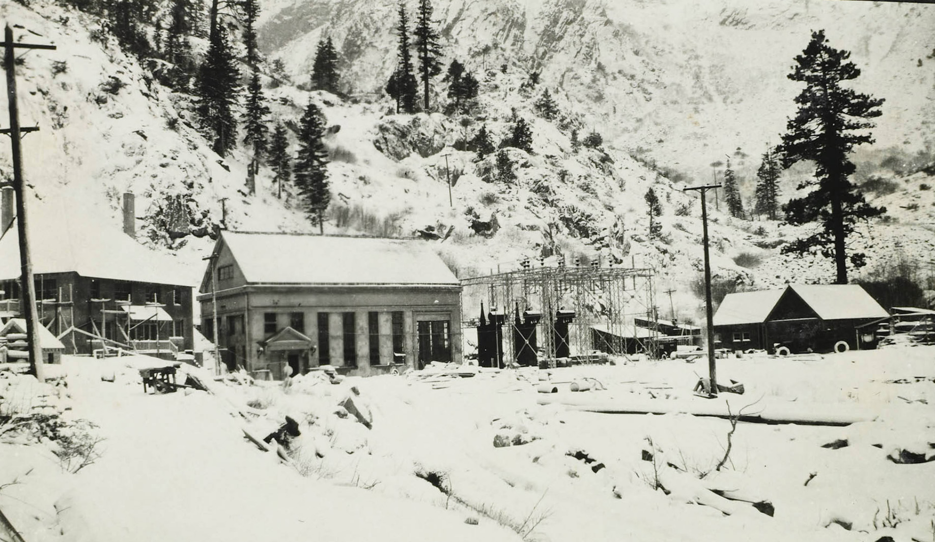
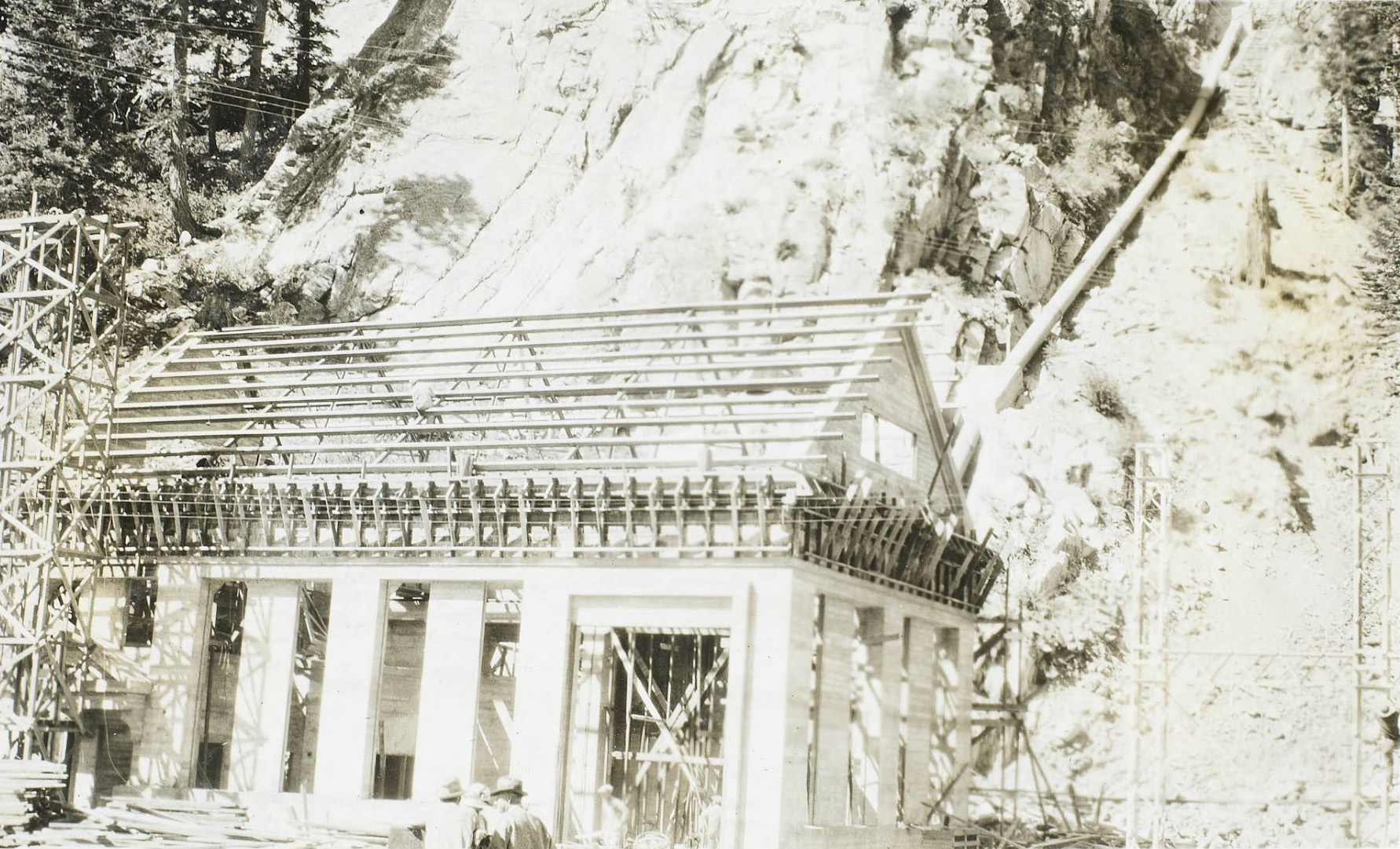
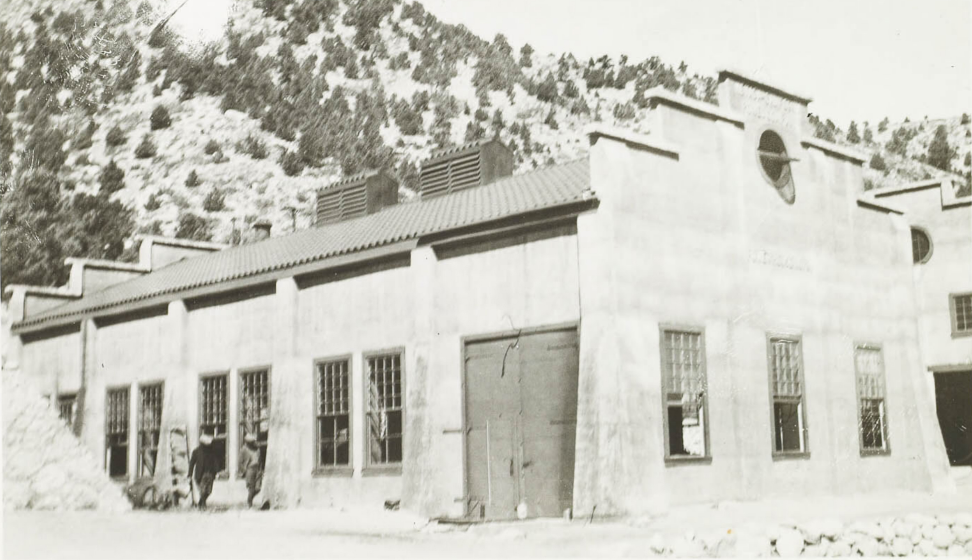
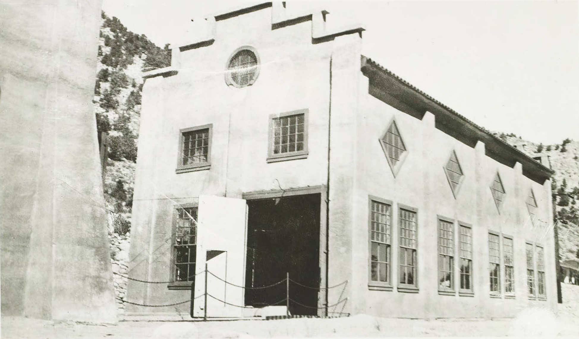
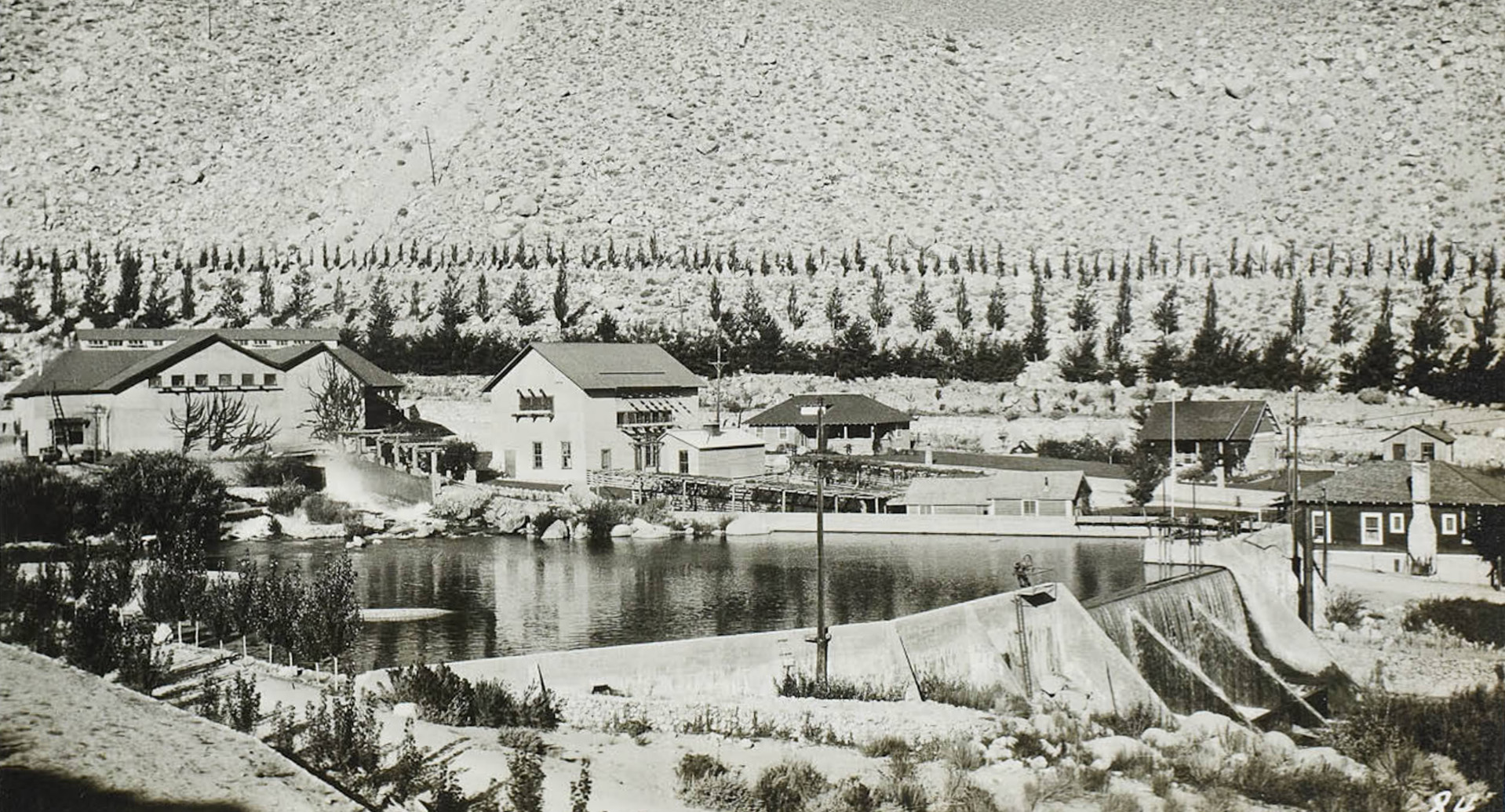
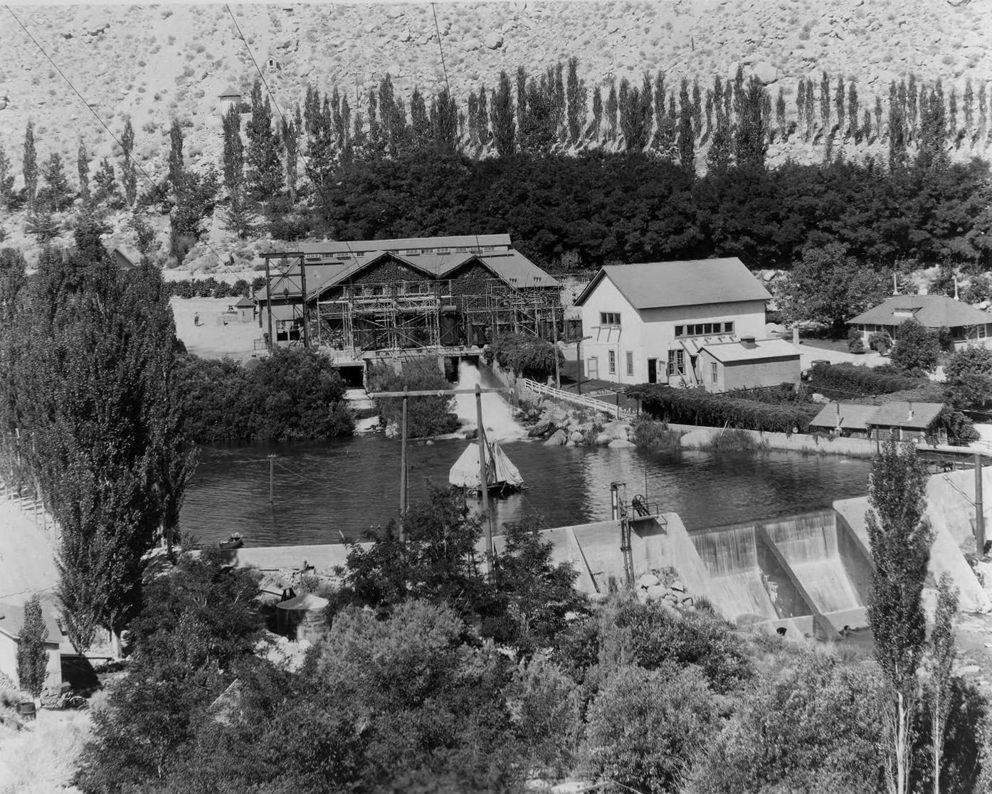
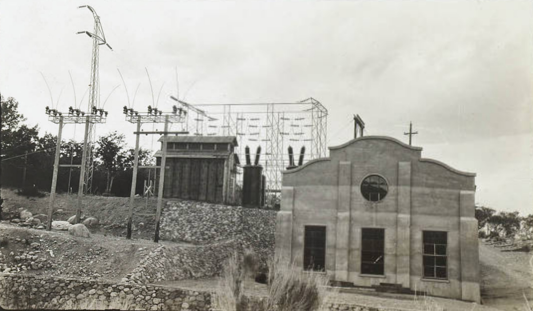
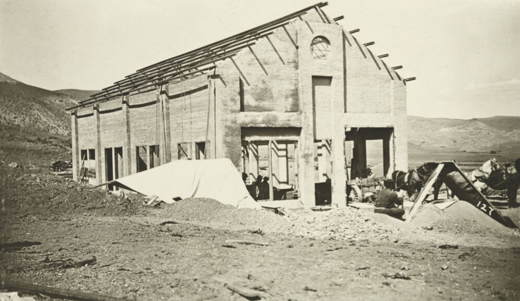 Jordan (Mill Creek) Powerhouse - 1910 |
|
 Jordan (Mill Creek) Powerhouse - 1910 |
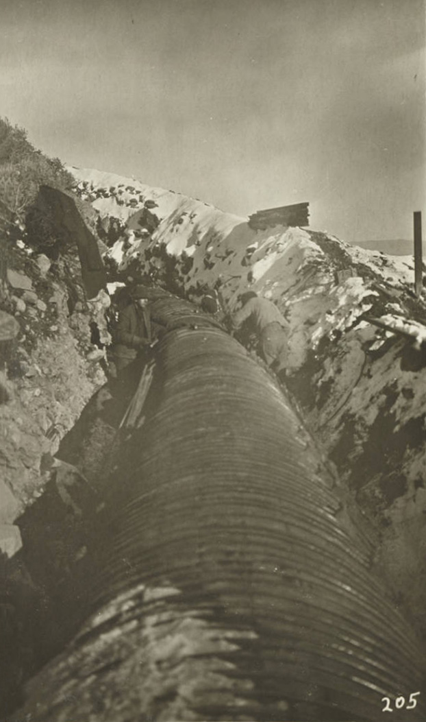
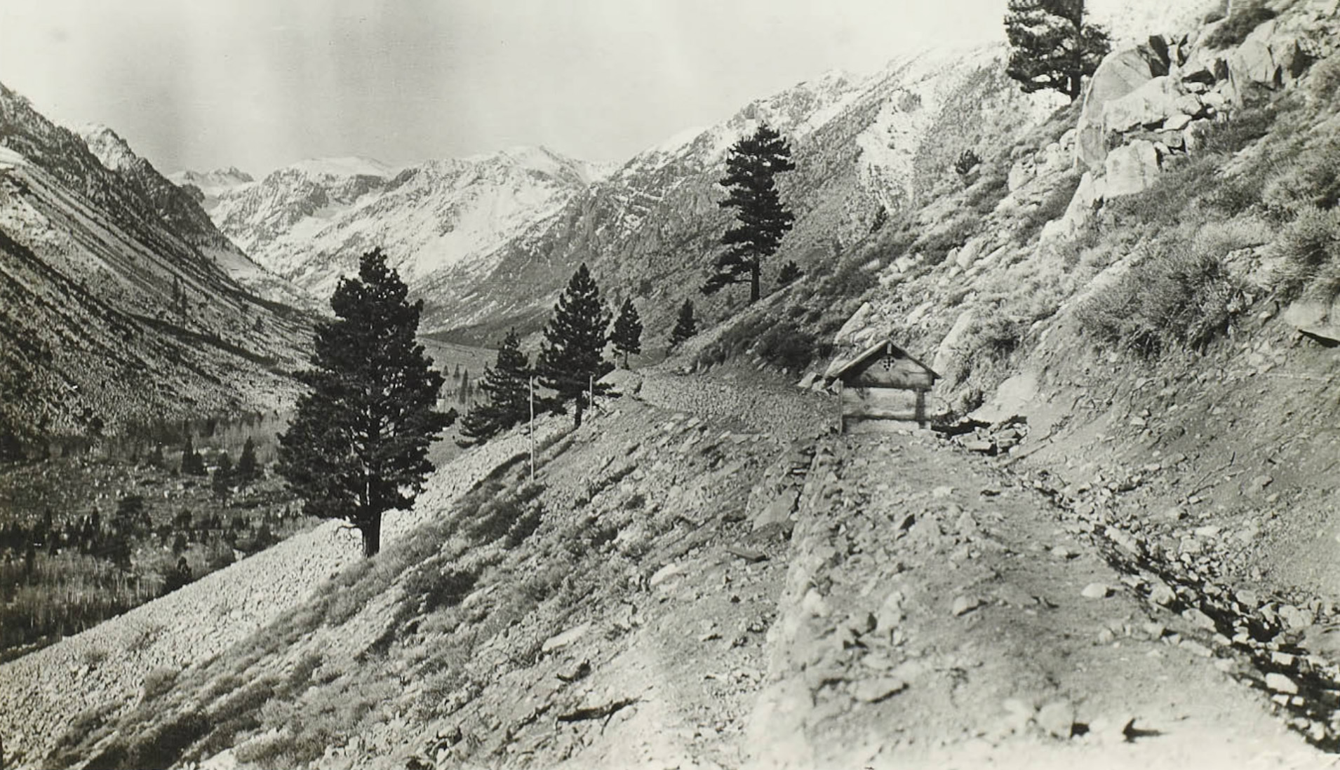
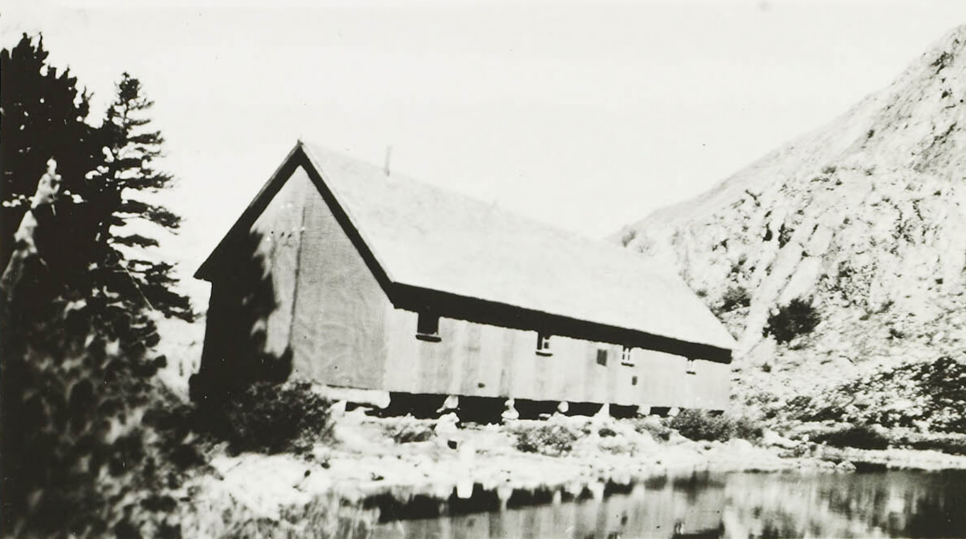
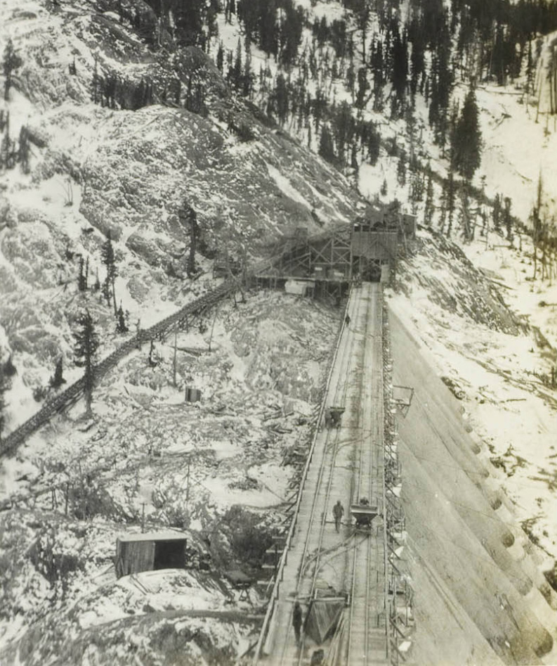
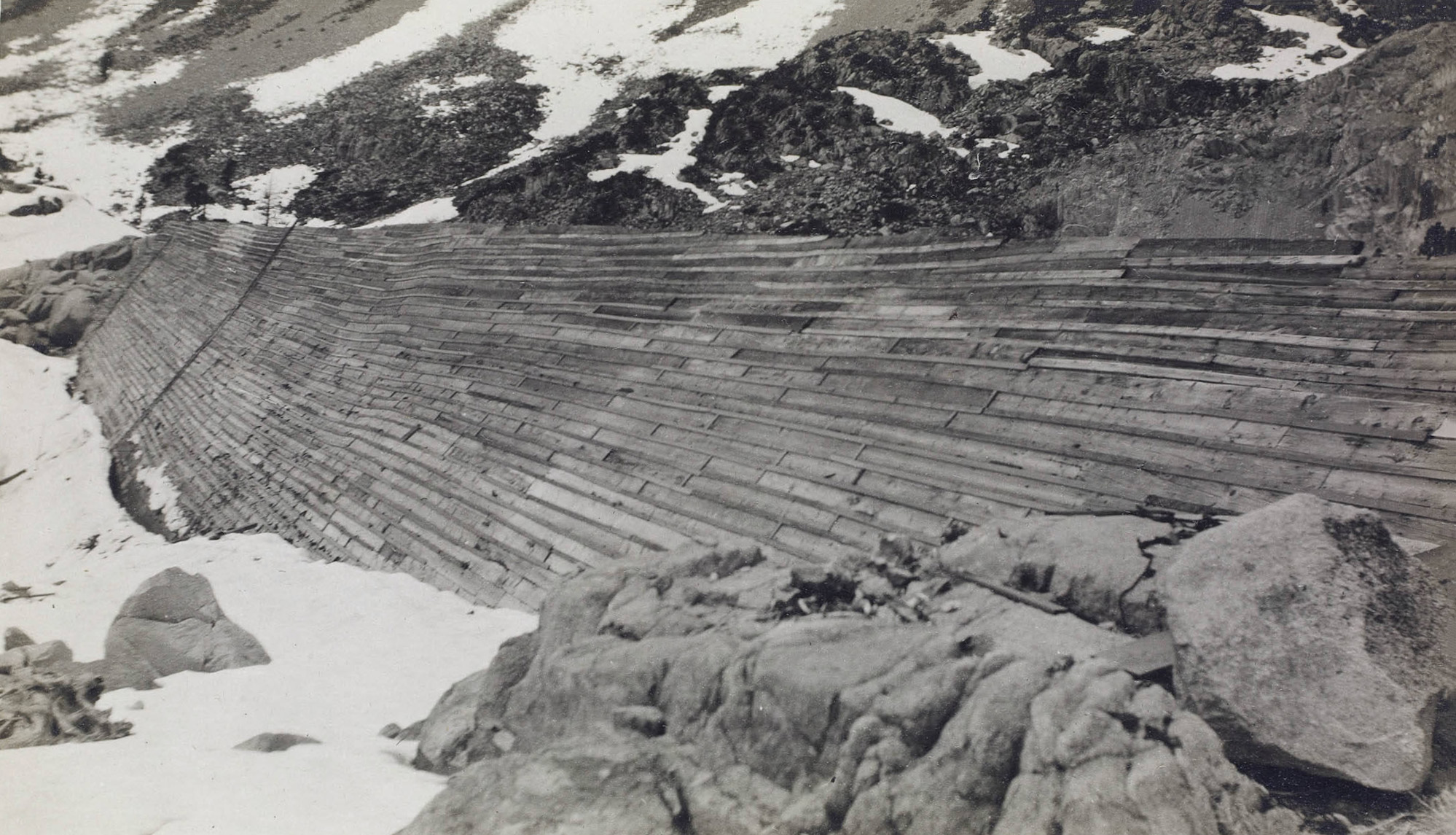
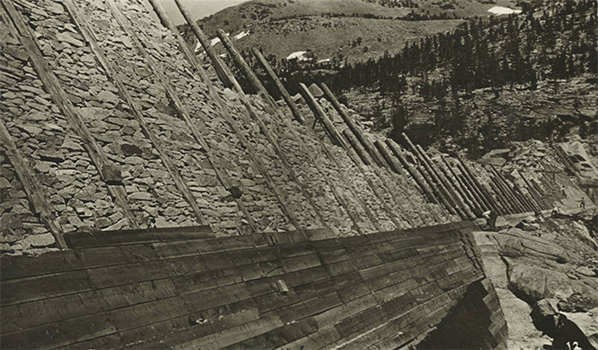
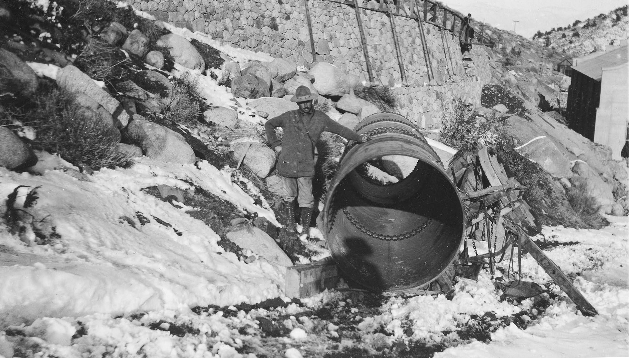
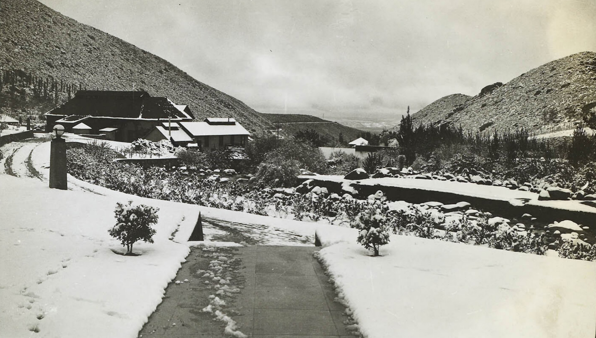
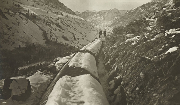 Wood pipe after a snow storm - looking up Mill Creek Canyon |
|
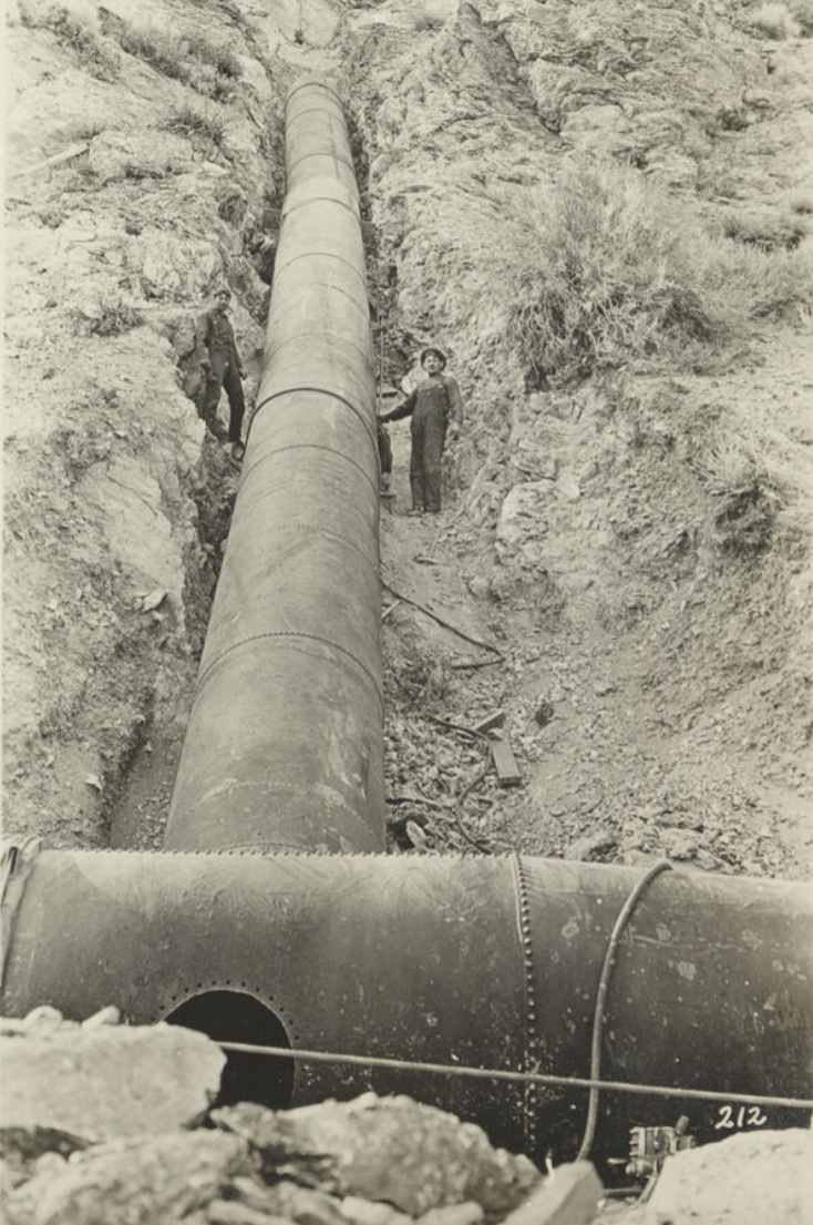
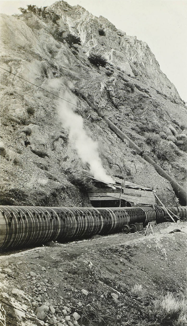
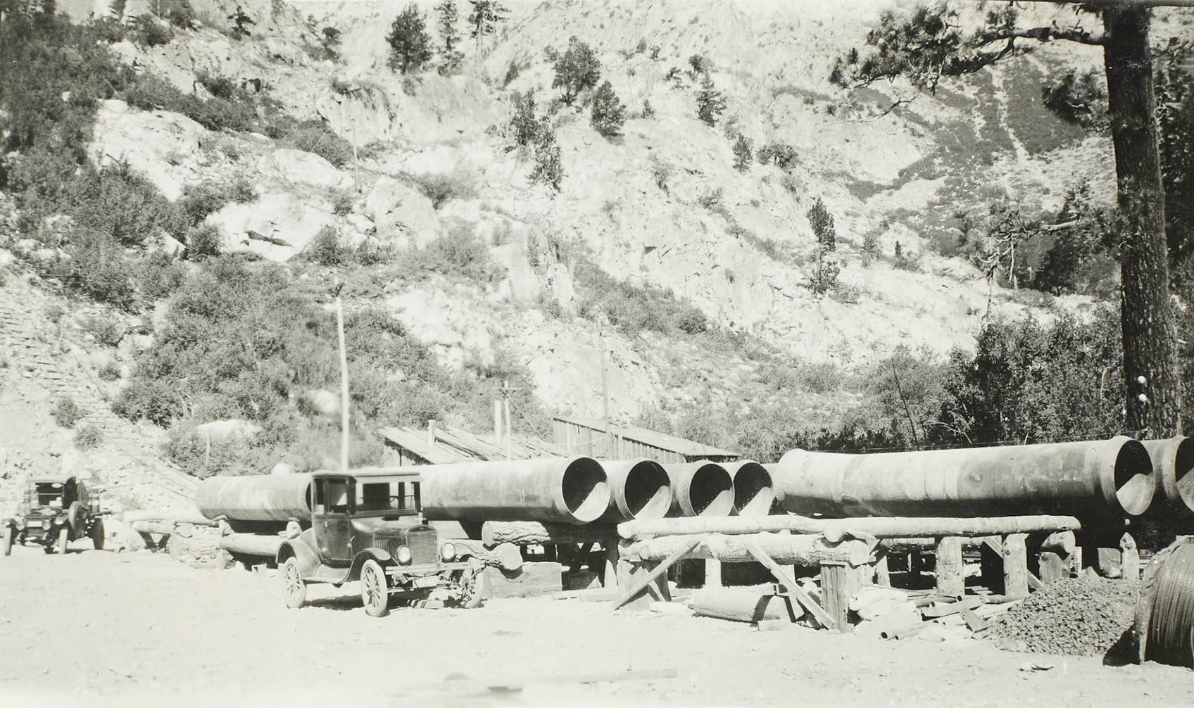
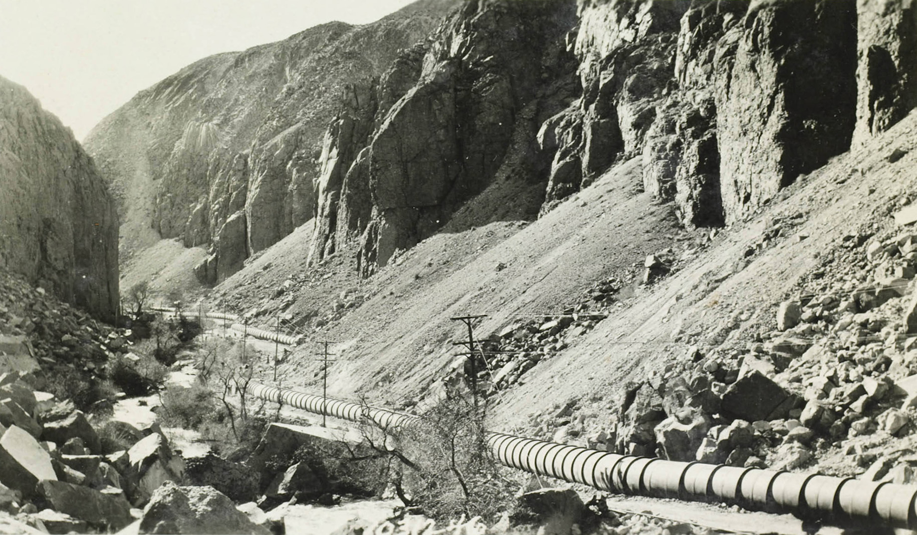
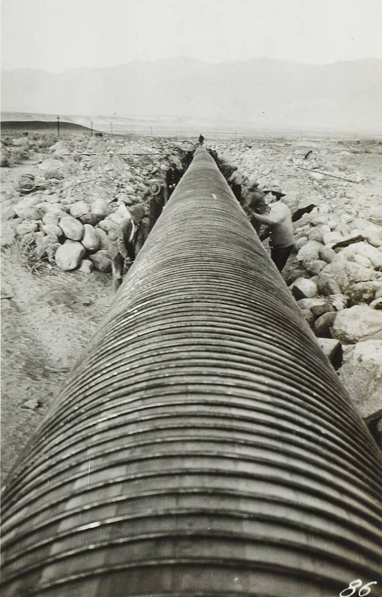
 Steel pipe line - Mill Creek Plant |
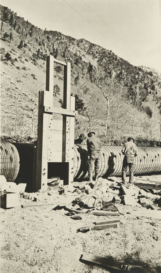
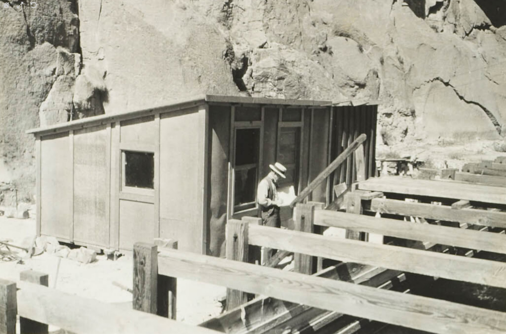
 Entering a section of 30" steel pipe |
|
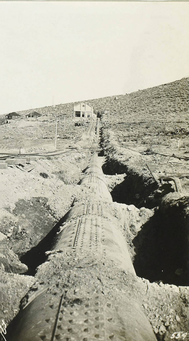
 Wood pipe in deep cut - lower end Mill Creek Plant |
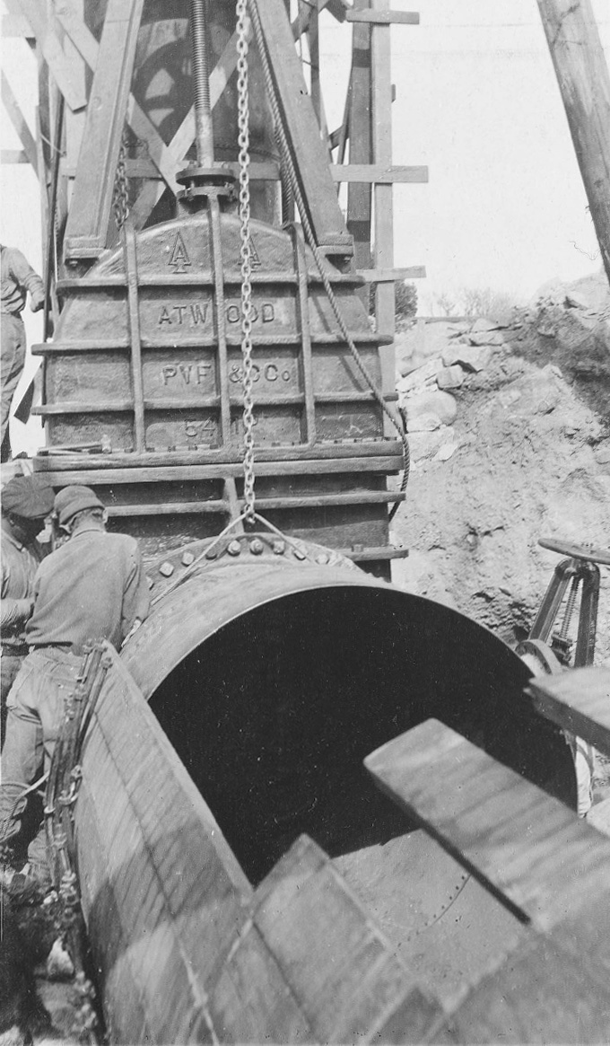
 Powe36" wood gate on wood pipe |
|
 Laying 48" wood pipe on forest reserve |
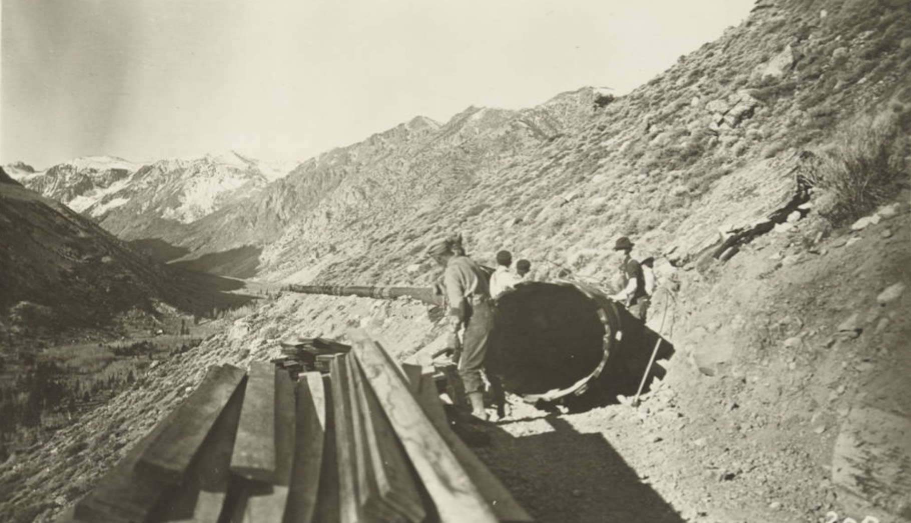
 Yarding out the pipe |
|
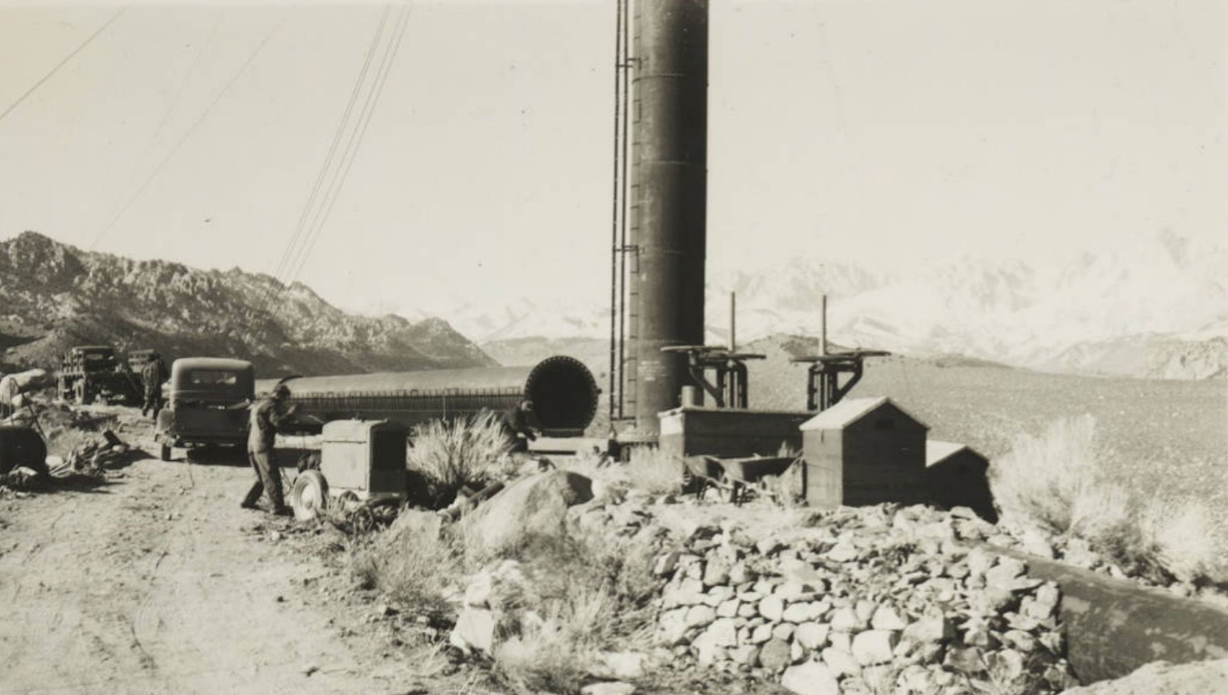
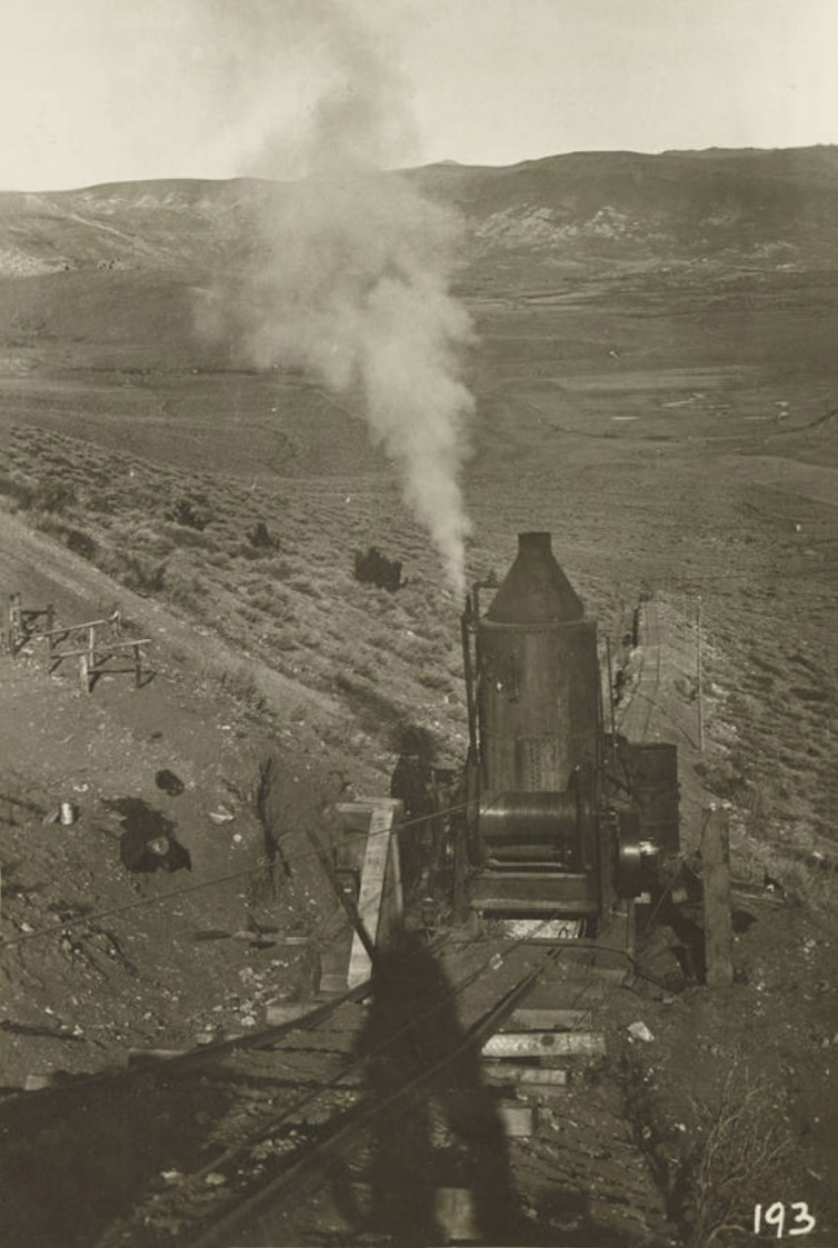 The donkey pulling itself up the hill. This was used to pull steel pipe up the hill. |
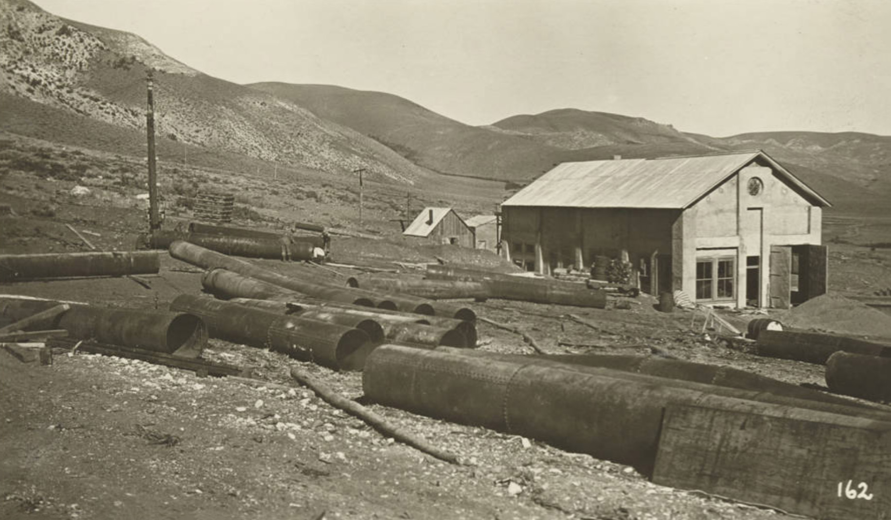
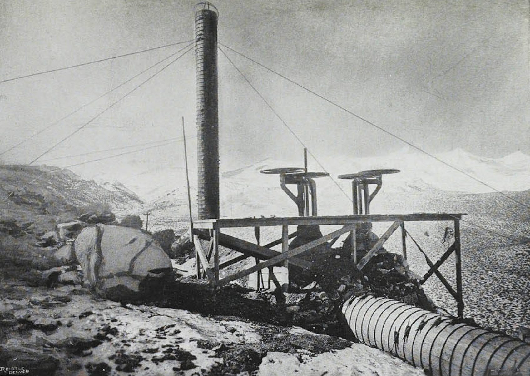
 Tee and three sections of stand pipe |
|
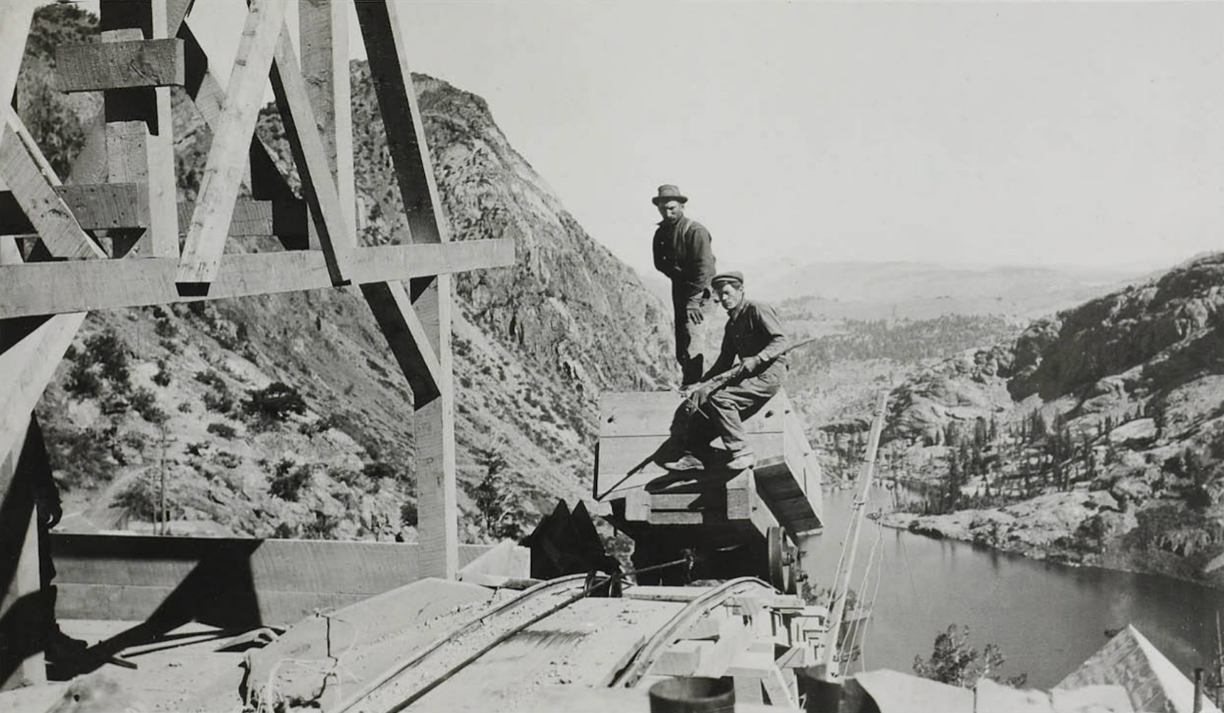
 Head ends |
 Engine (donkey) used to pull steel pipe up the hill. |
|
Lundy Powerhouse Mill Creek |
|
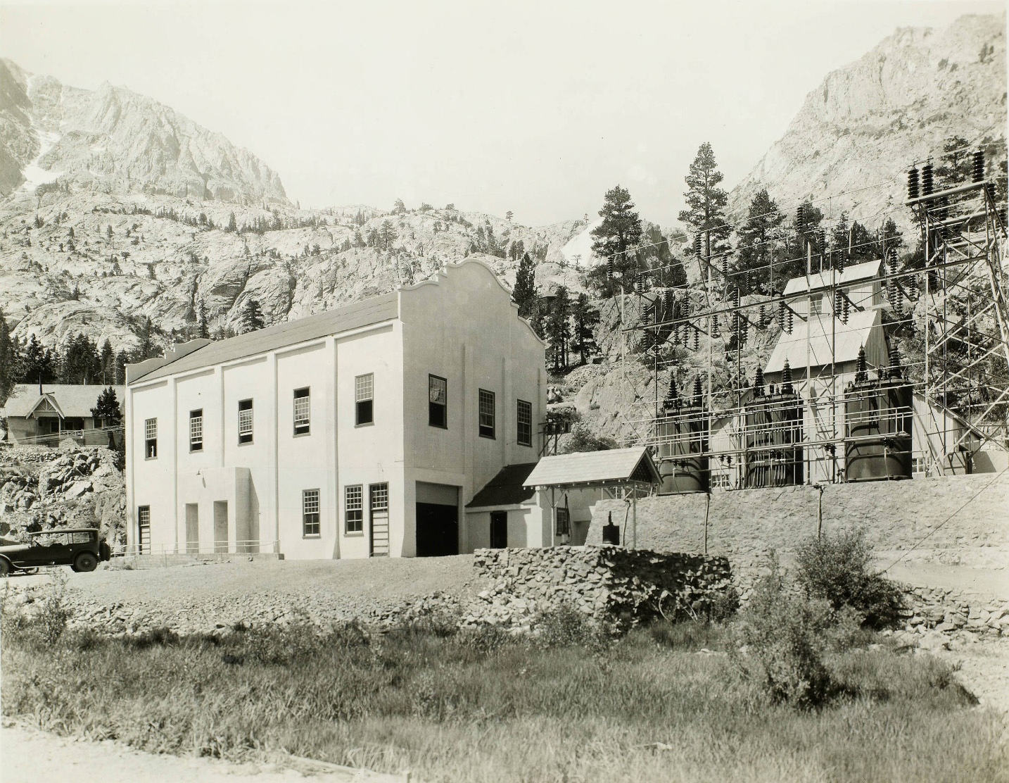
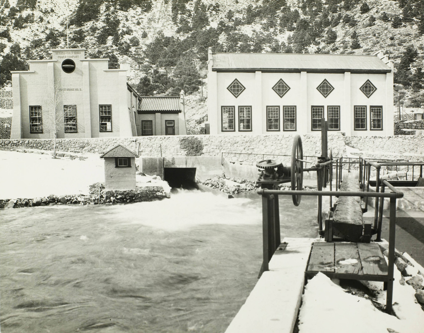
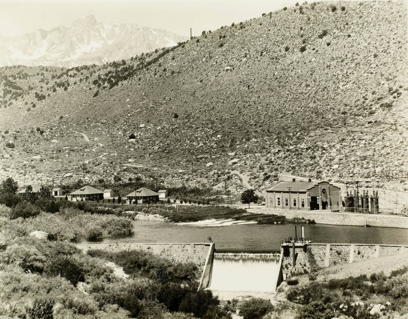
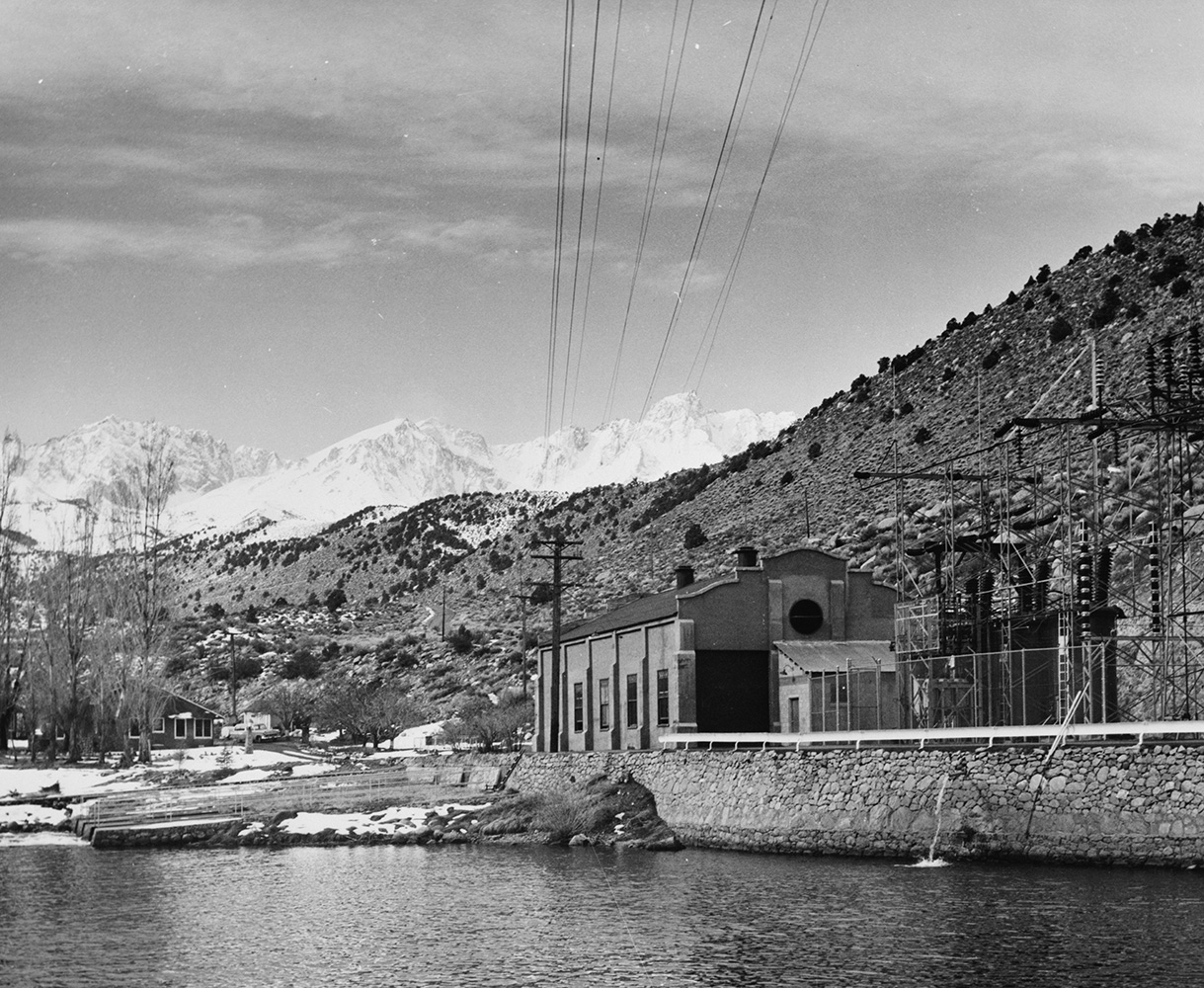
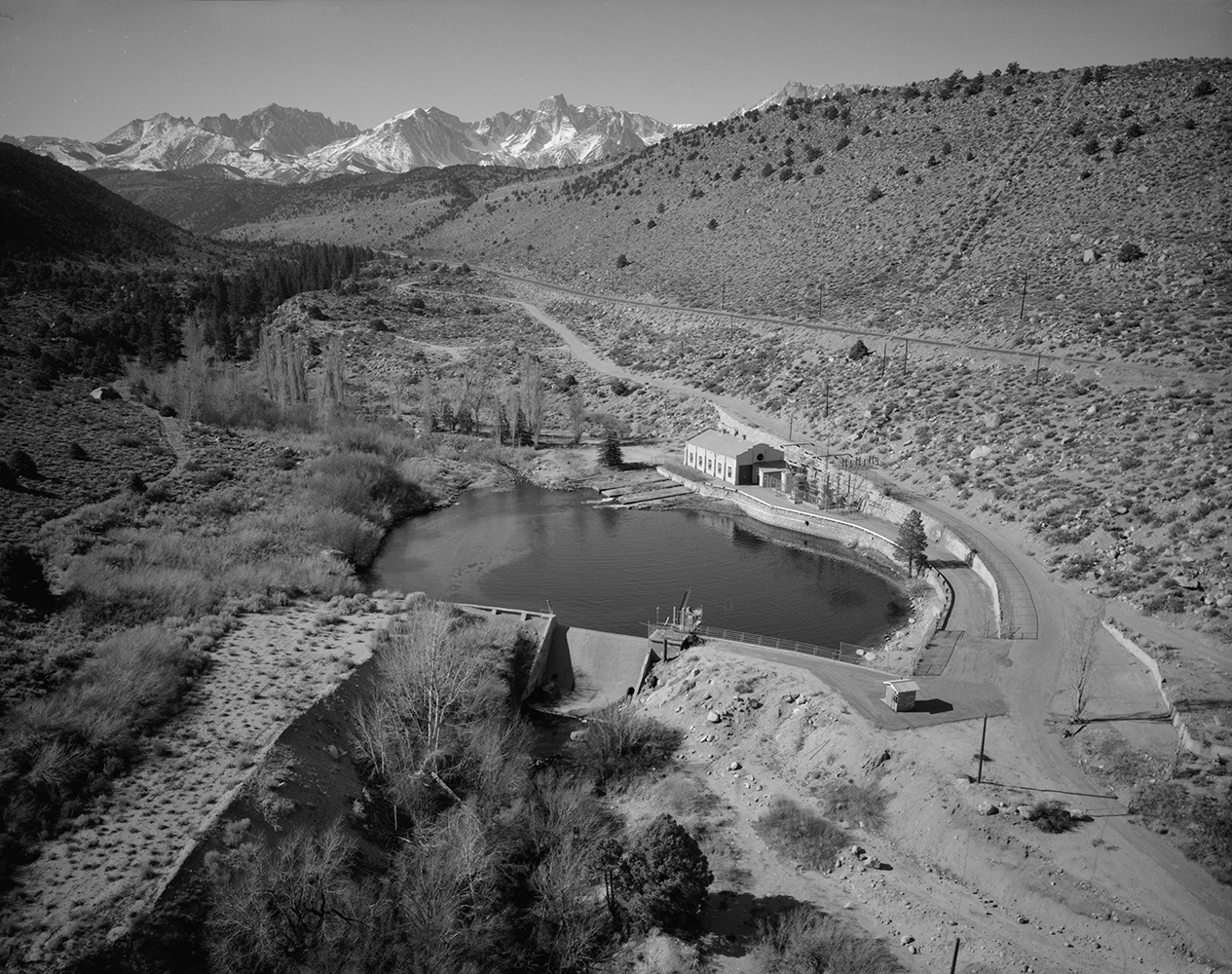
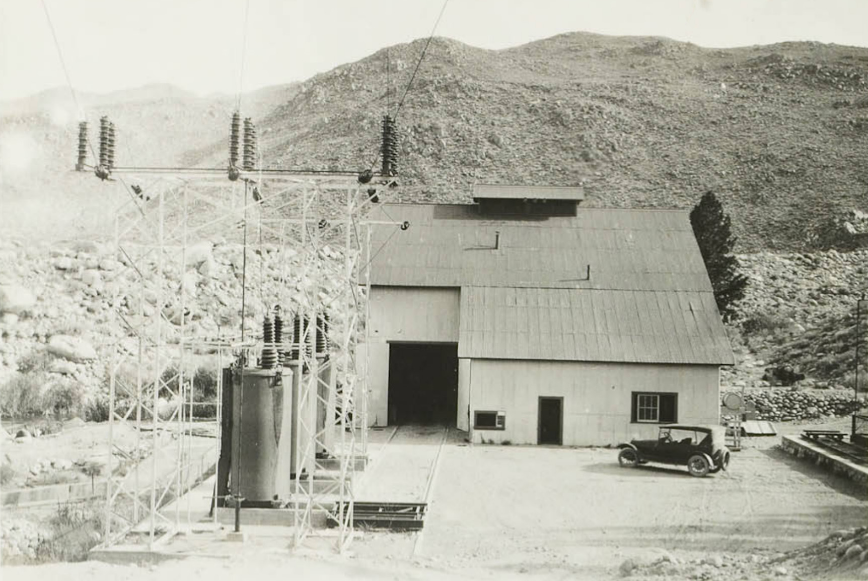
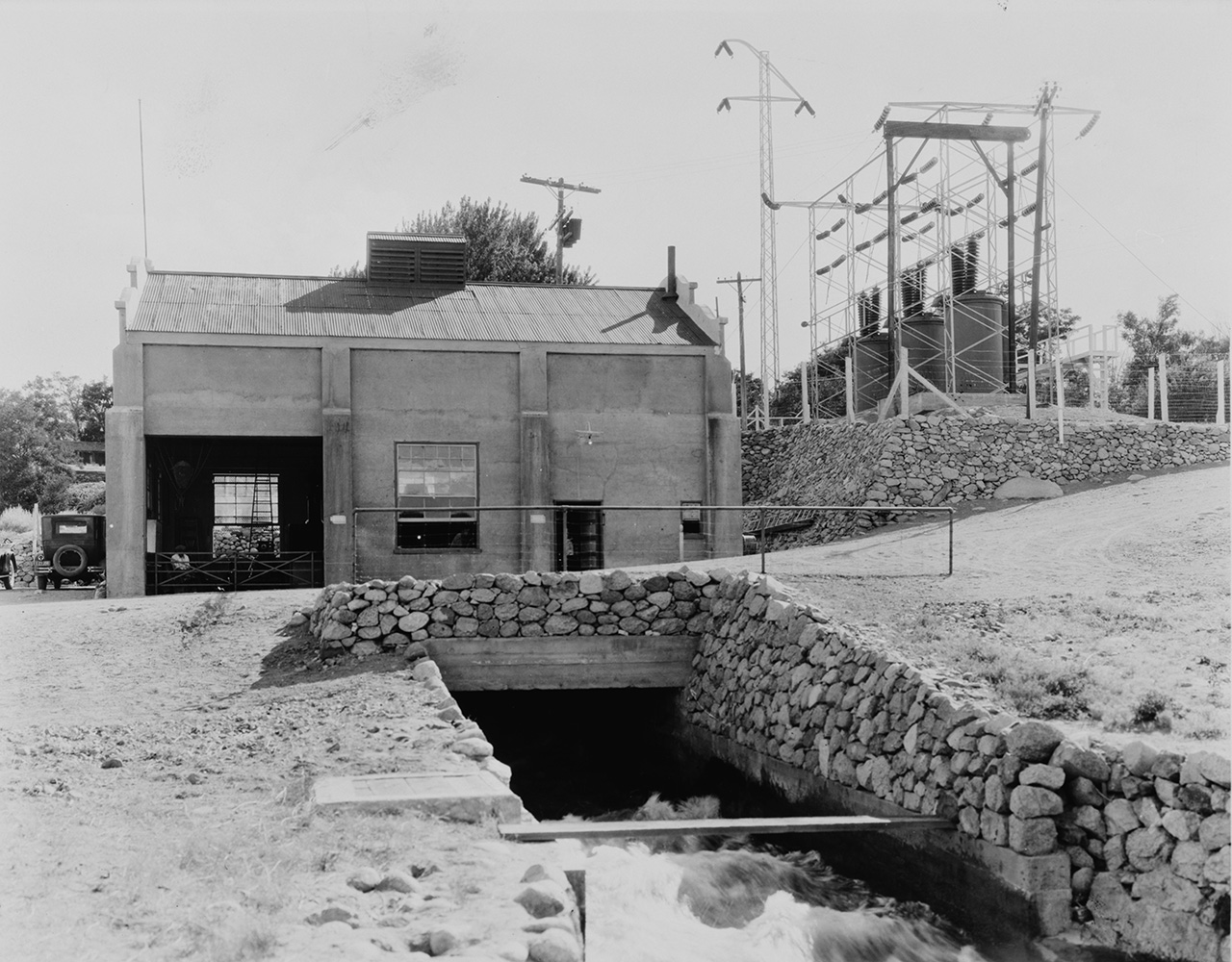
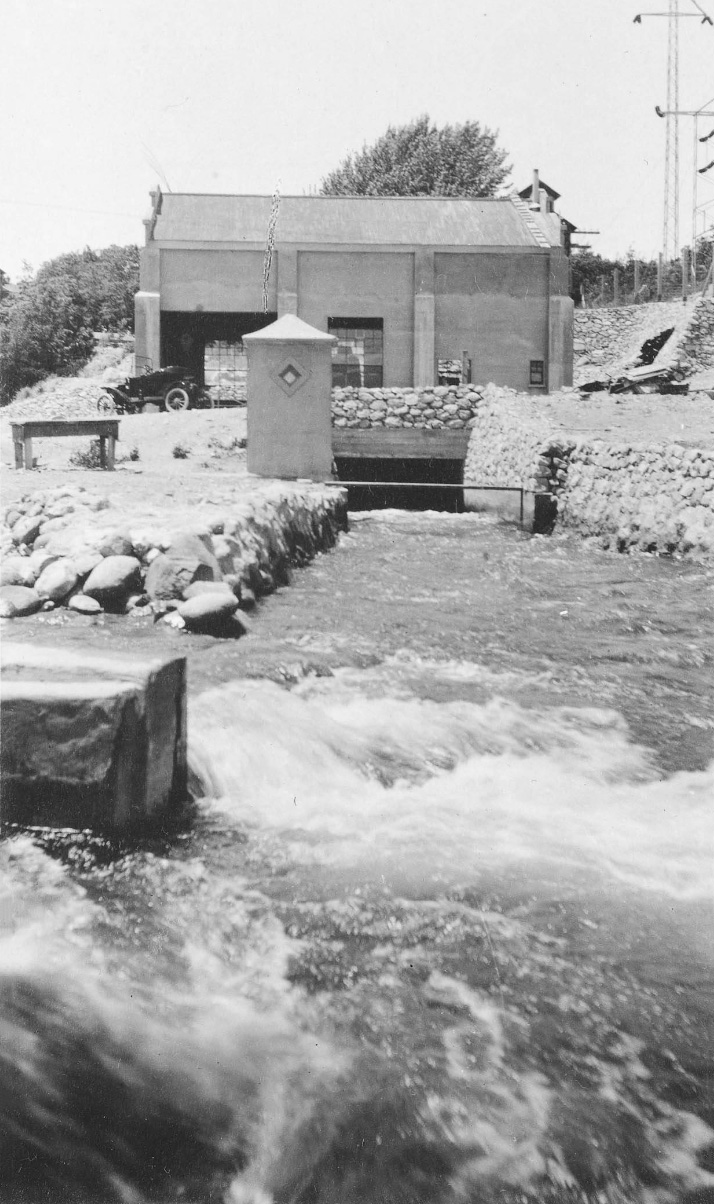
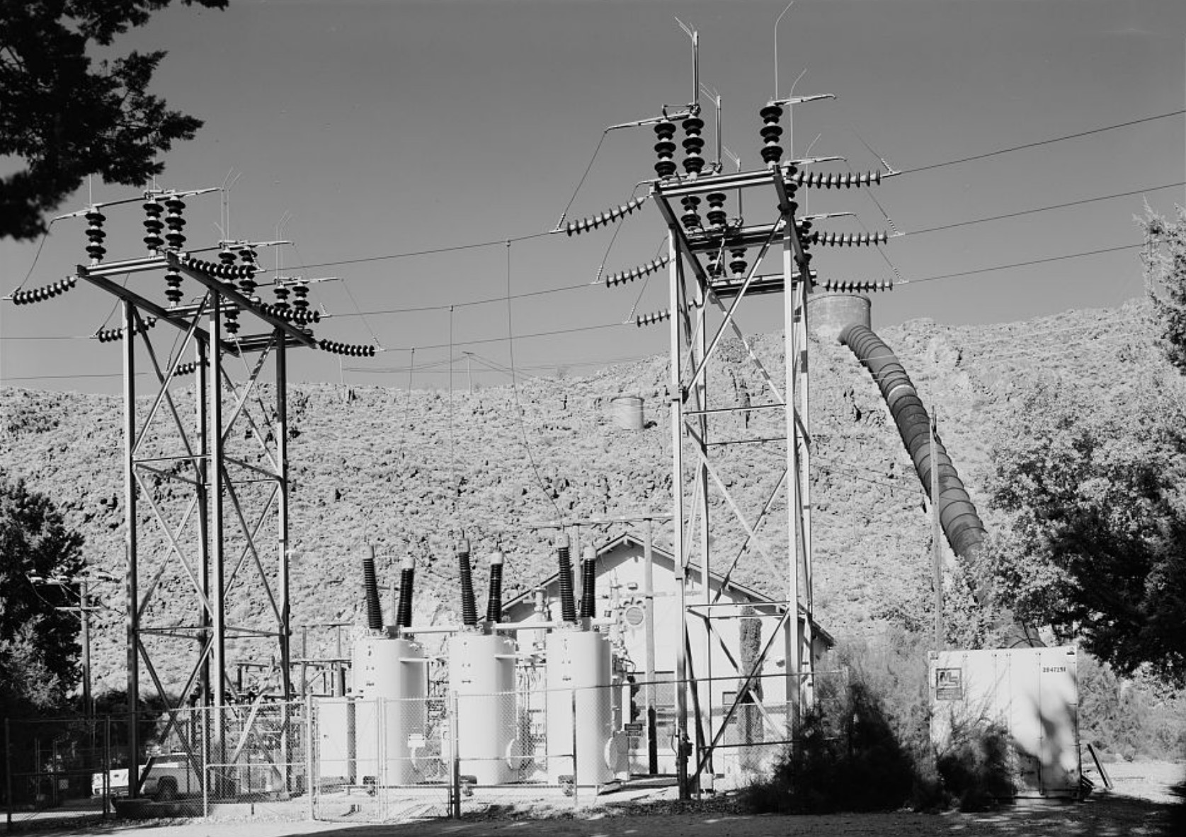
 Lundy (Mill Creek) Plant Water from Lundy Lake Reservoir is supplied to the plant through 11,840' of wood stave pipeline and 3,105' of steel pressure line of from 36" to 48" in diameter. The generating equipment consists of two horizontal impulse water wheels, direct-connected to two alternating current generators having a combined capacity of 3,300 Kv-a. Power from the Mill Creek Plant is transmitted to Leevining Creek Plant #3, where connection is made to the balance of the System. This plant also supplies power to the Mineral County power system of Nevada. |
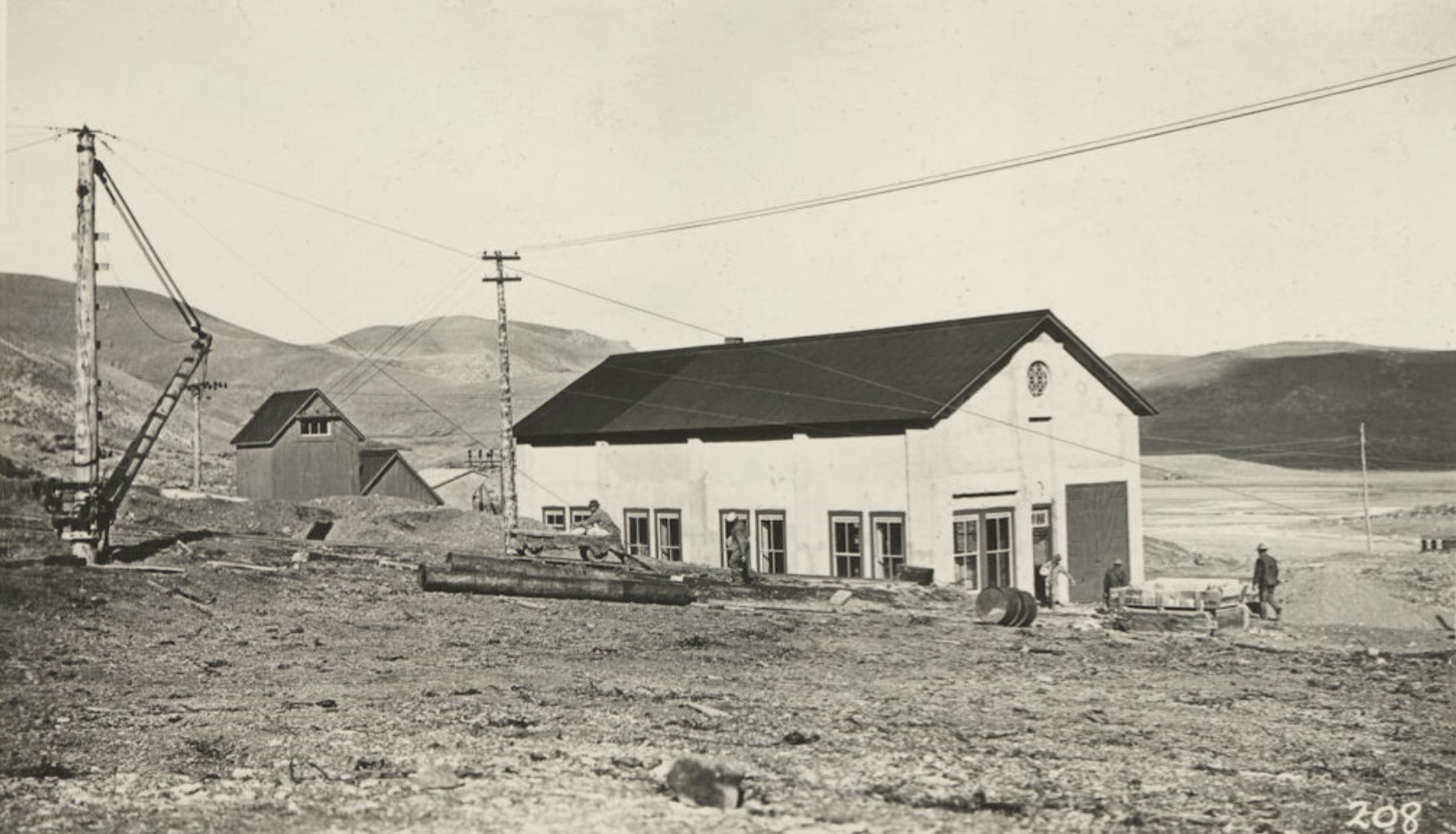
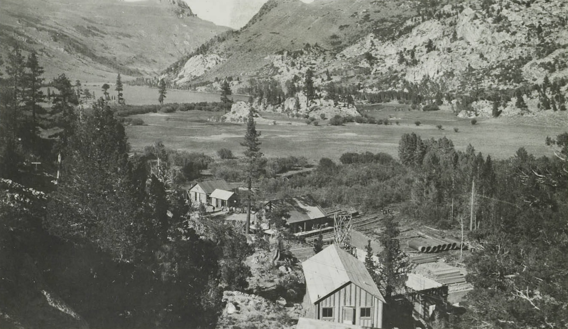
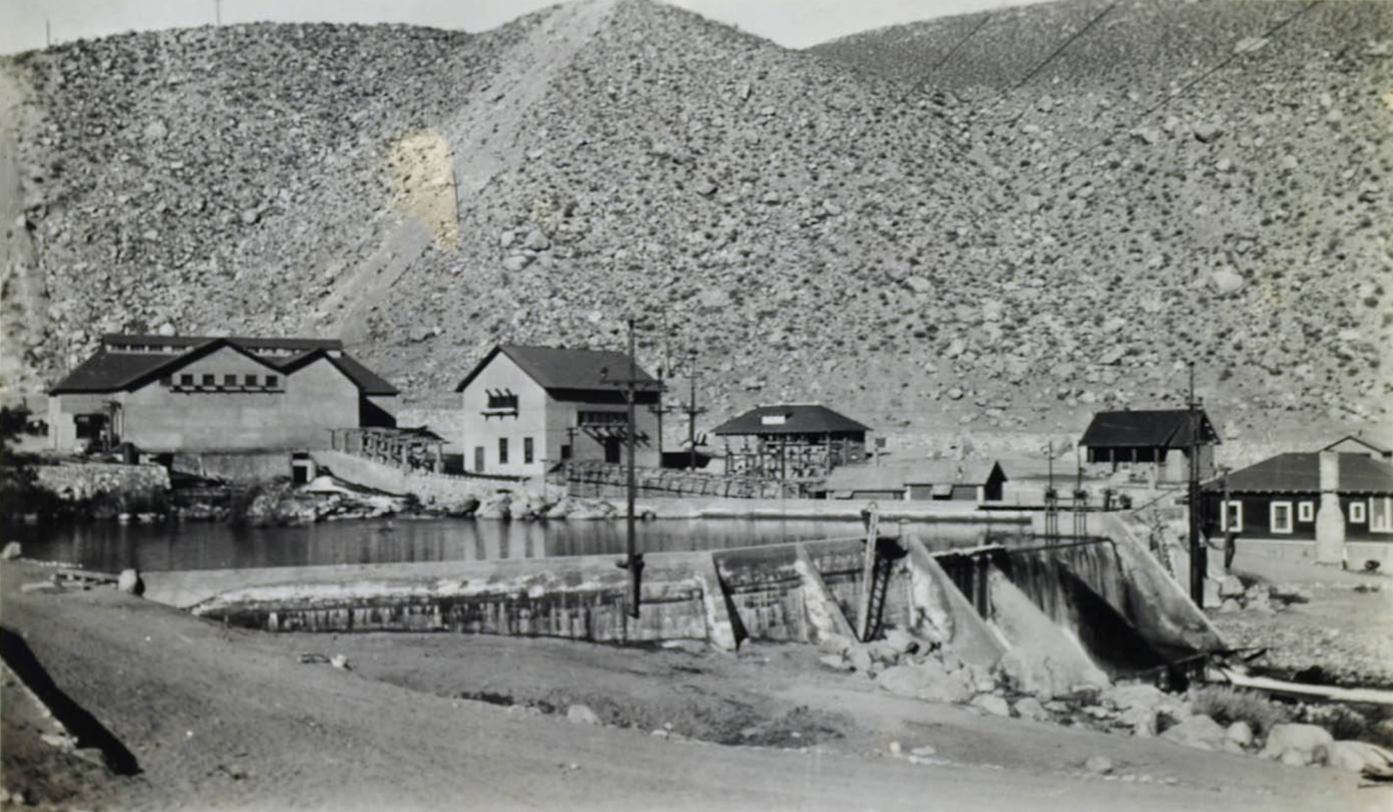
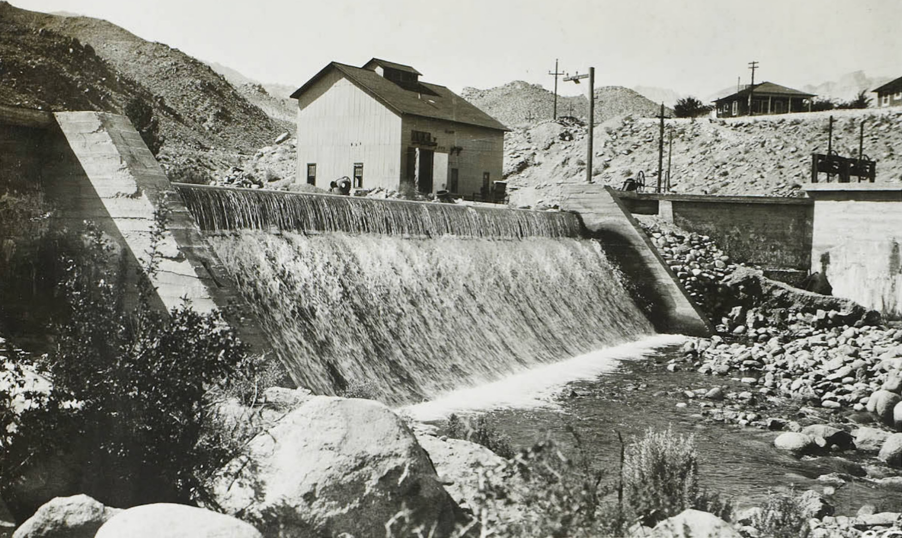
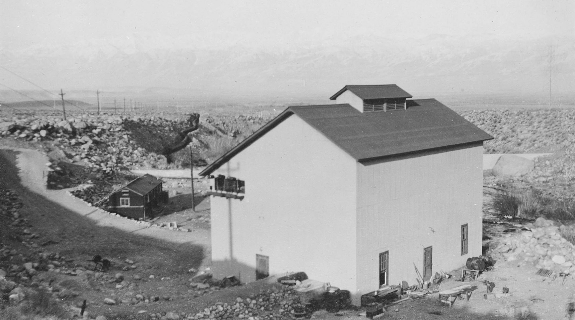
 Lundy Lake Powerhouse |
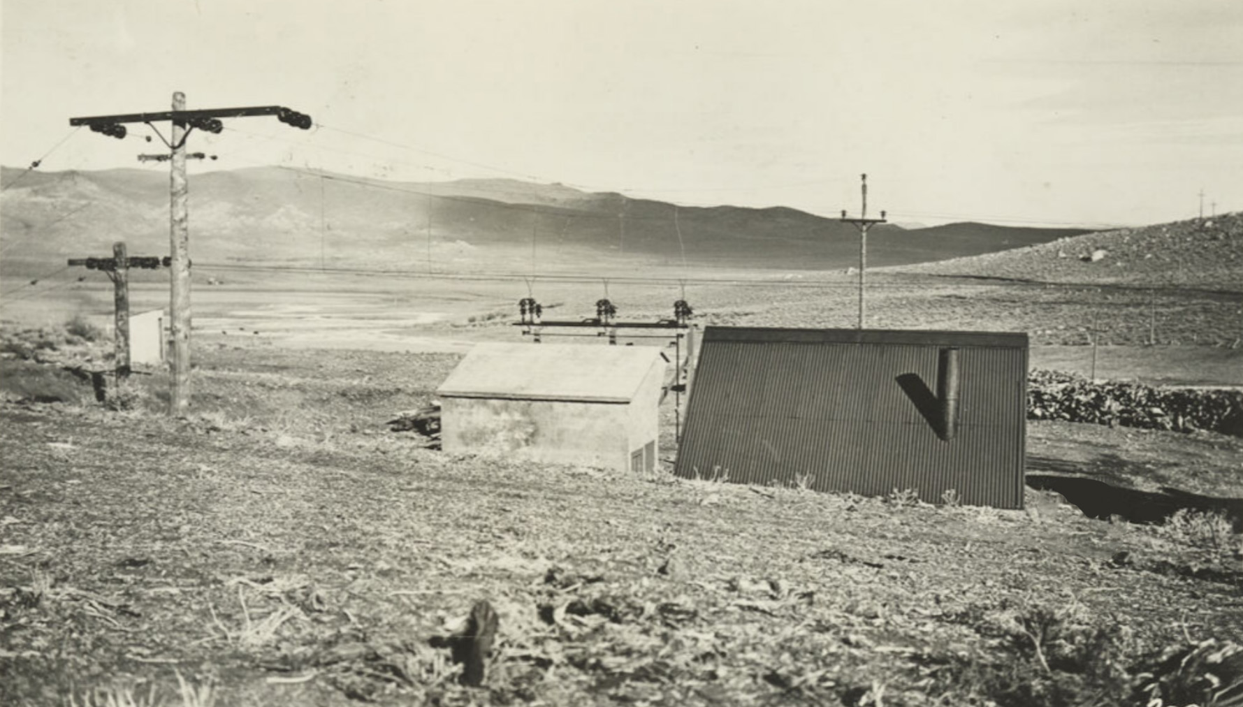
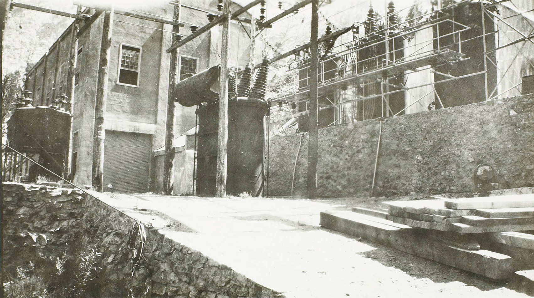
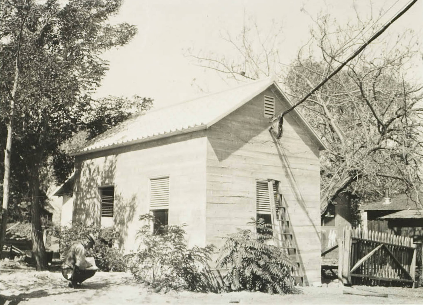
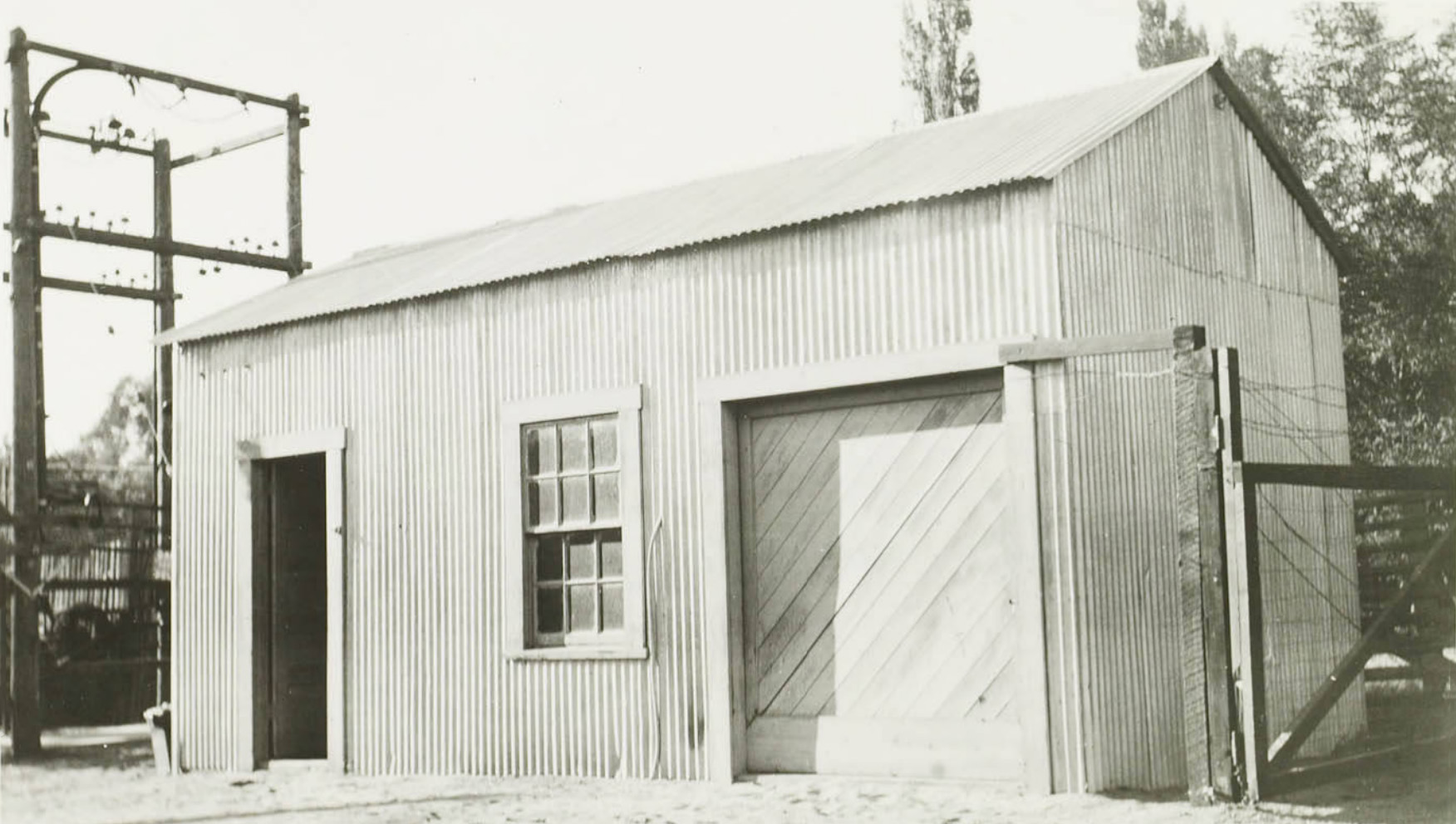
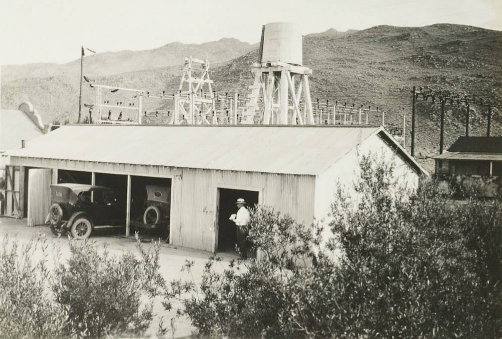
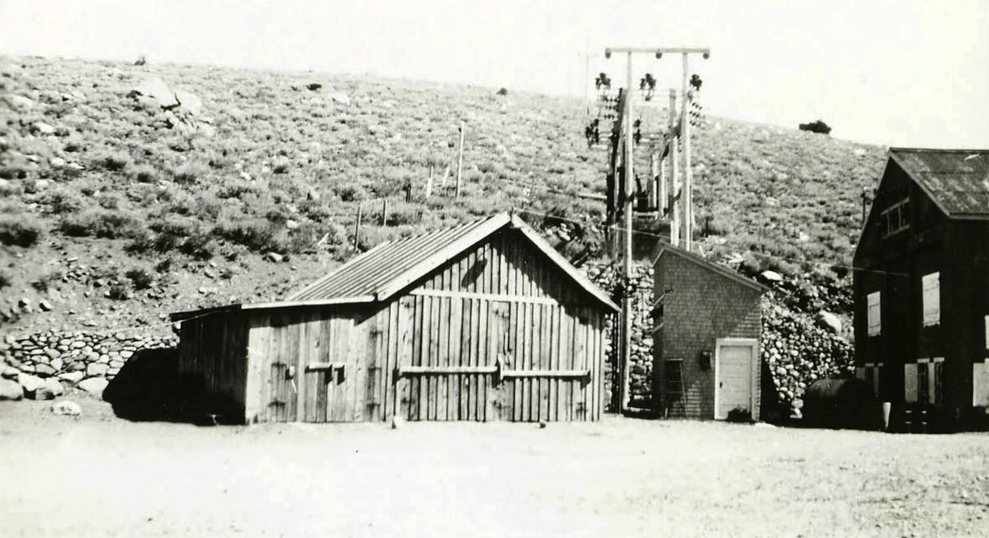 Mill Creek garage and lightning arrestor |
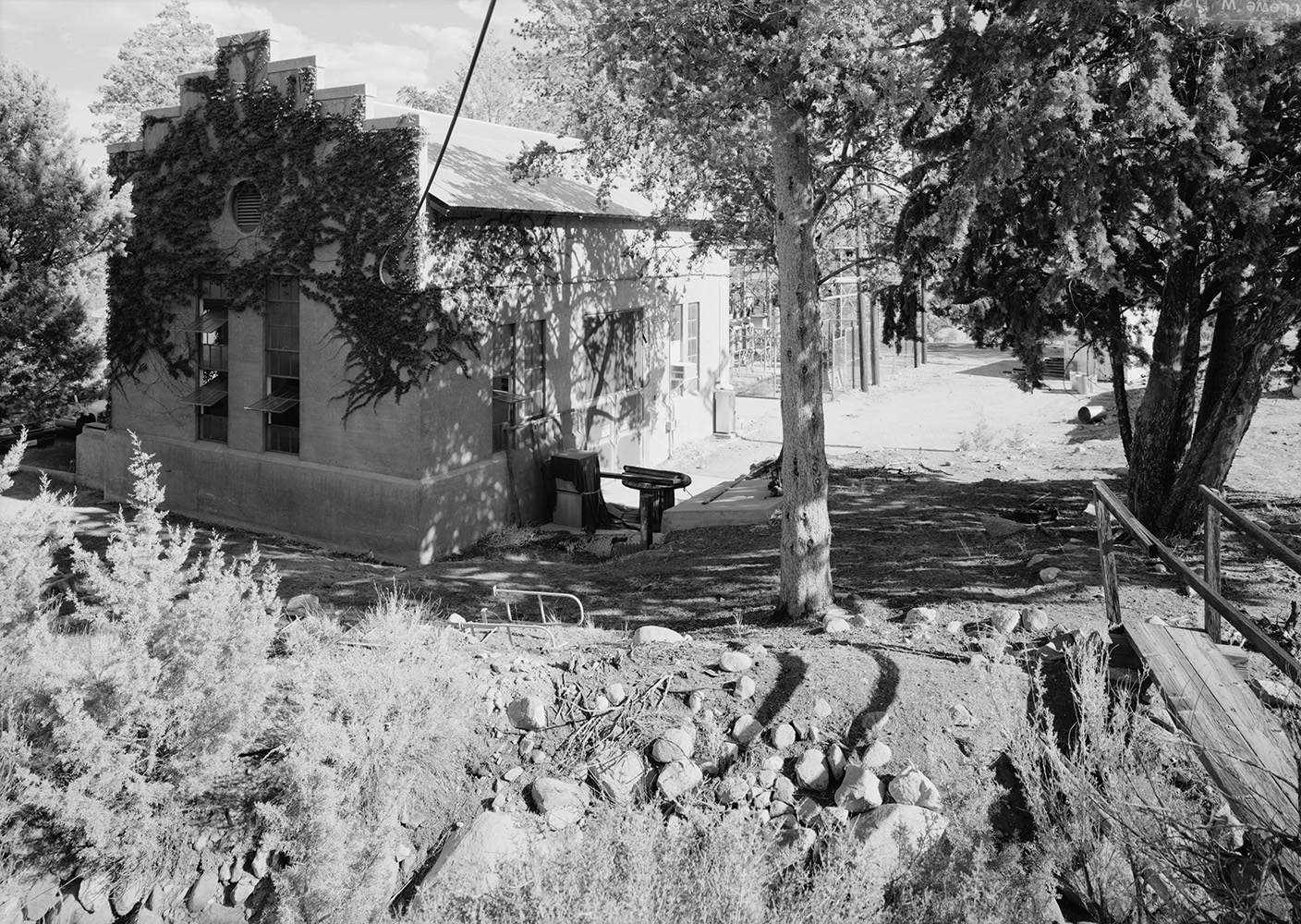
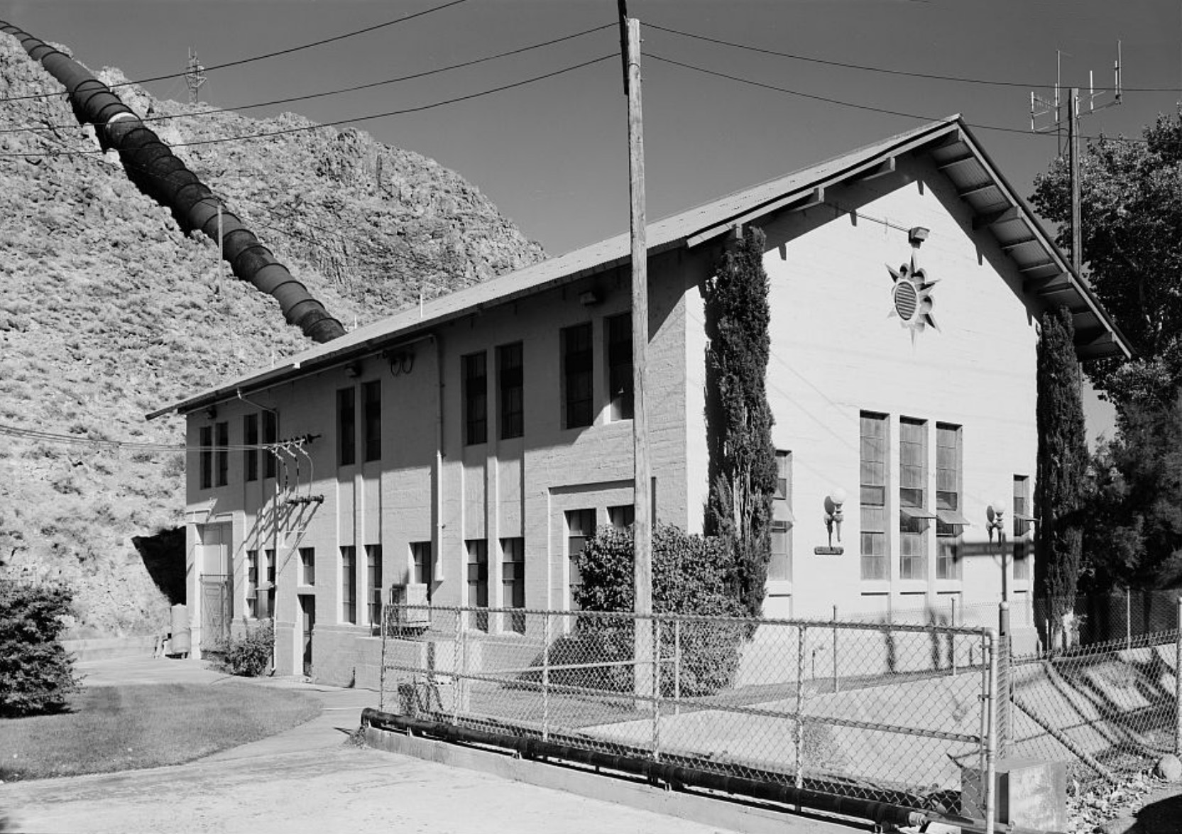
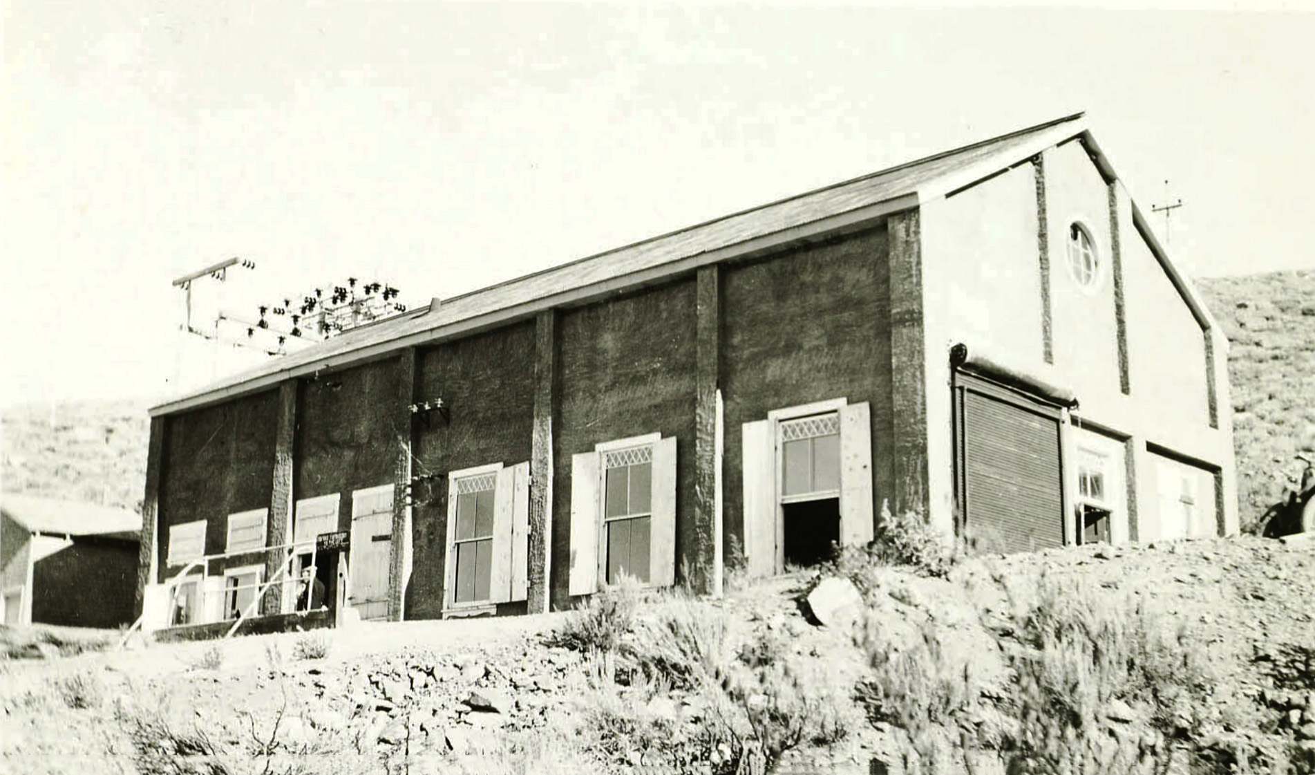 Mill Creek Powerhouse |
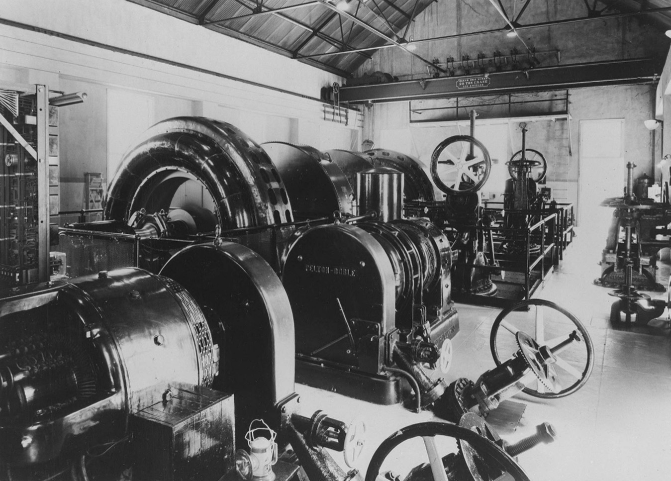
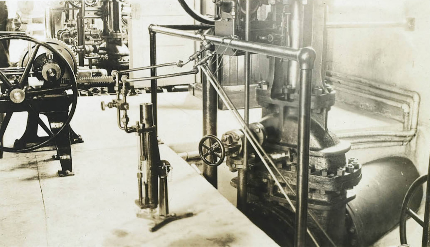
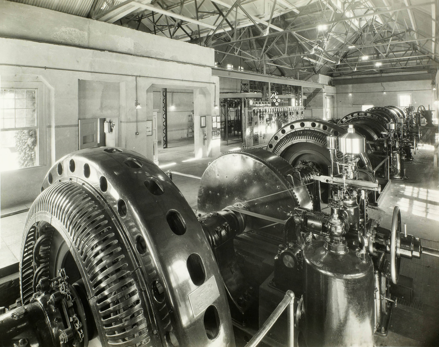
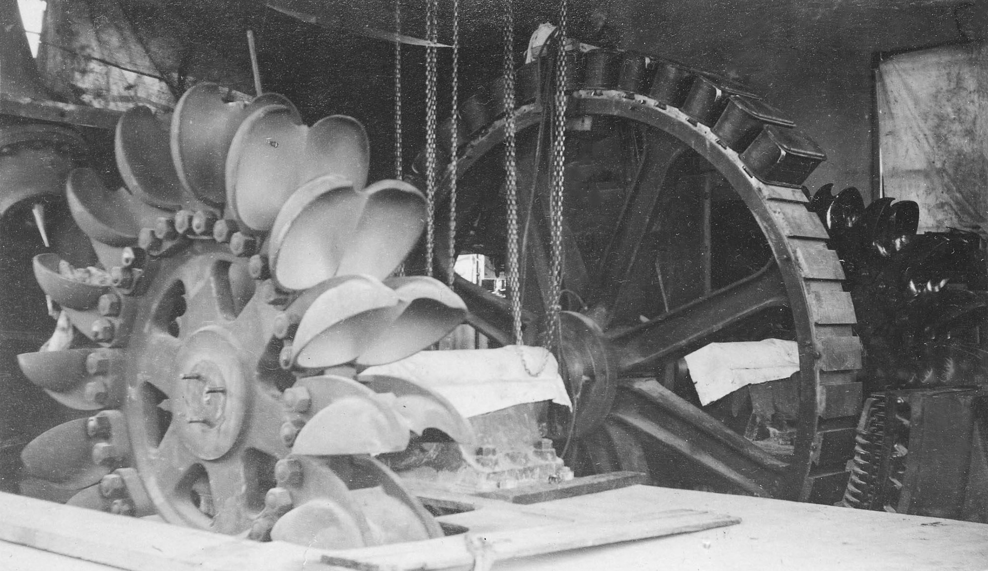
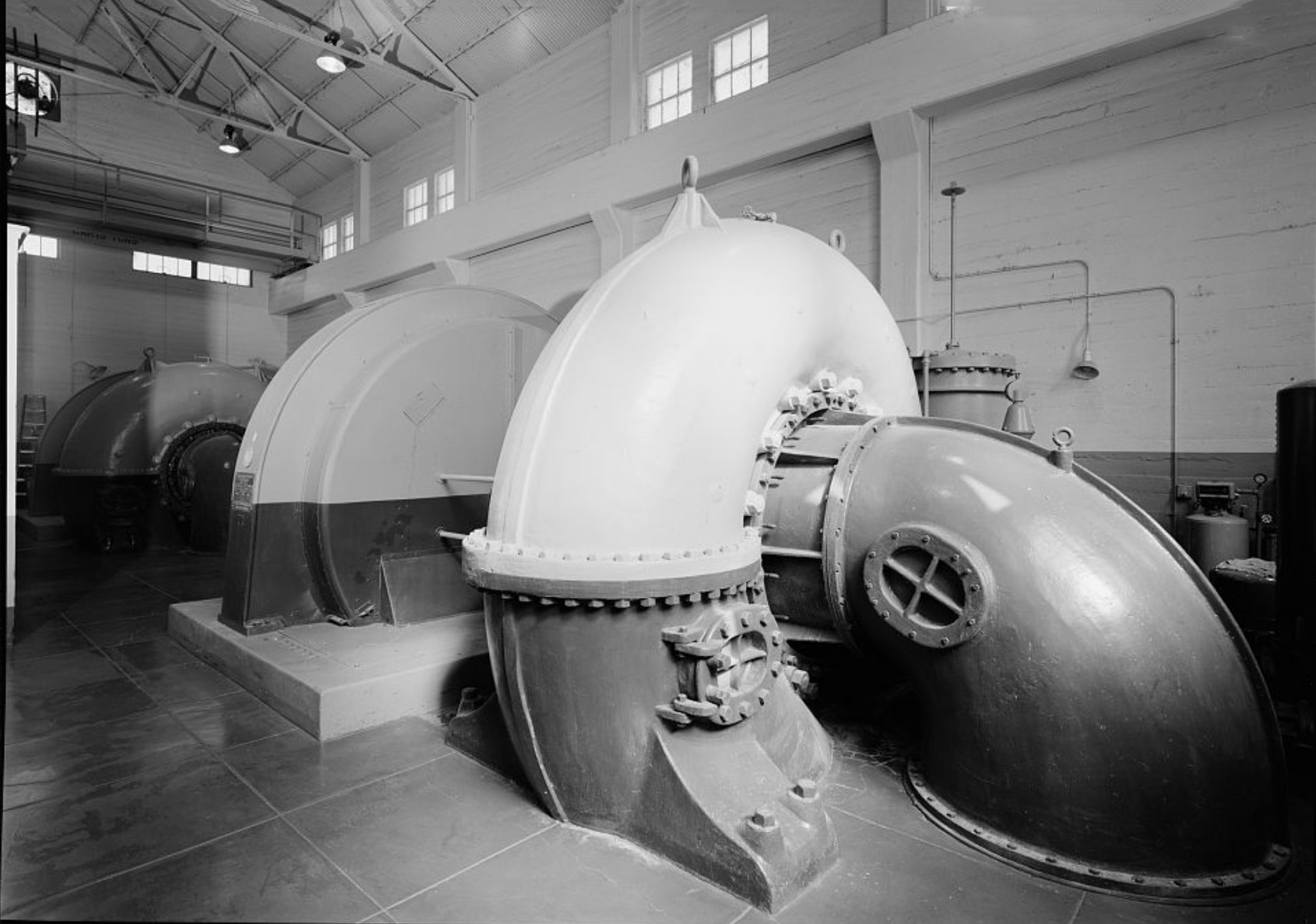
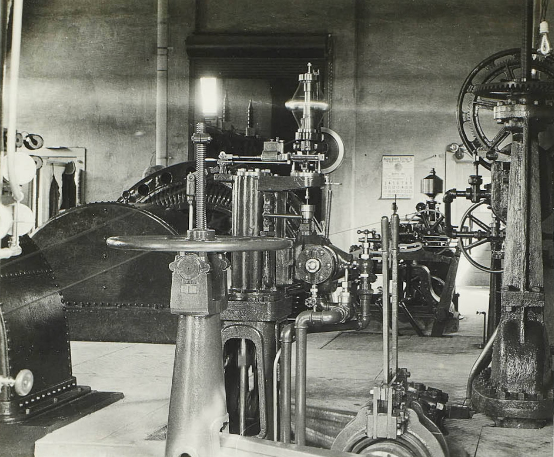 Interior of the Lundy powerhouse showing the automatic governor and the gate valves. |
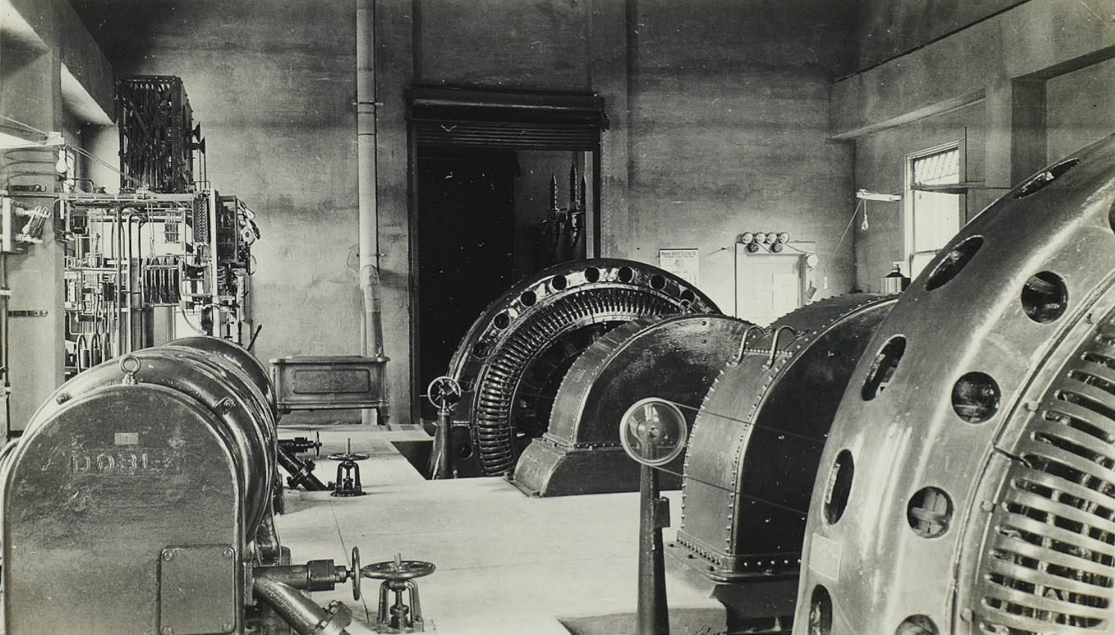 Lundy Lake Powerhouse interior showing two 1500 KW generators |
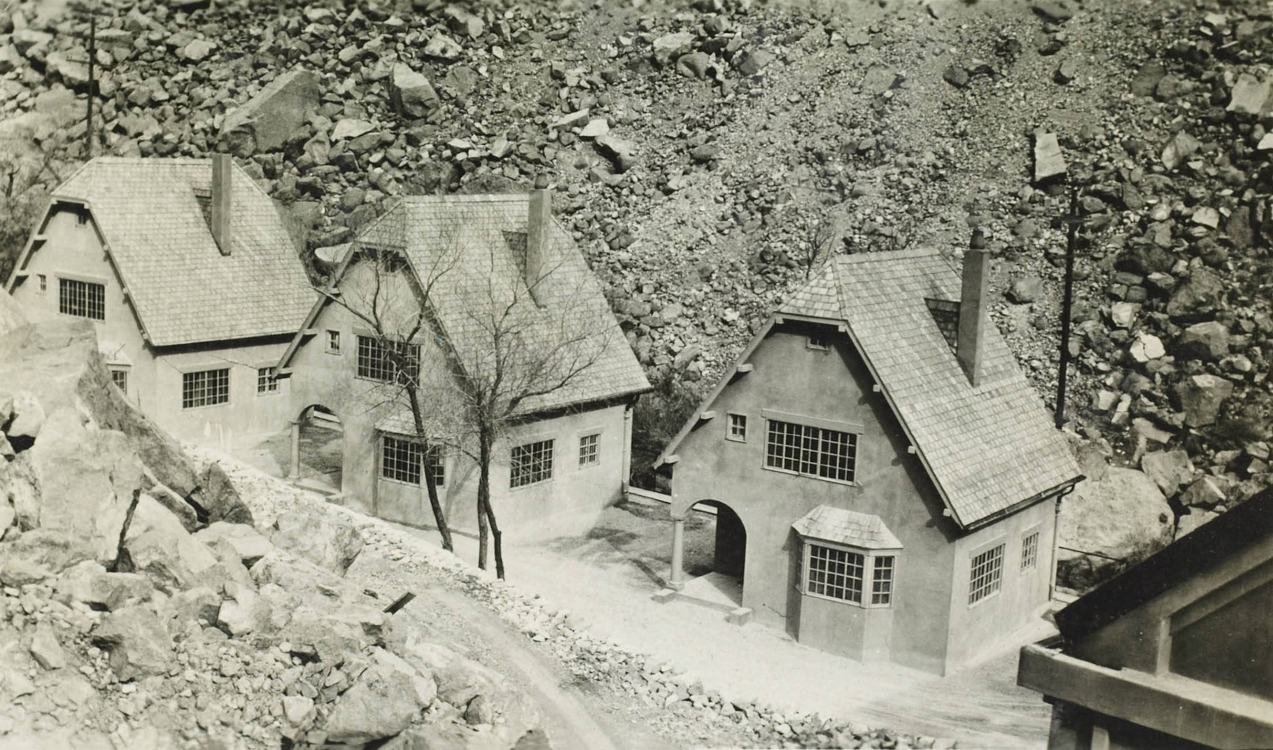
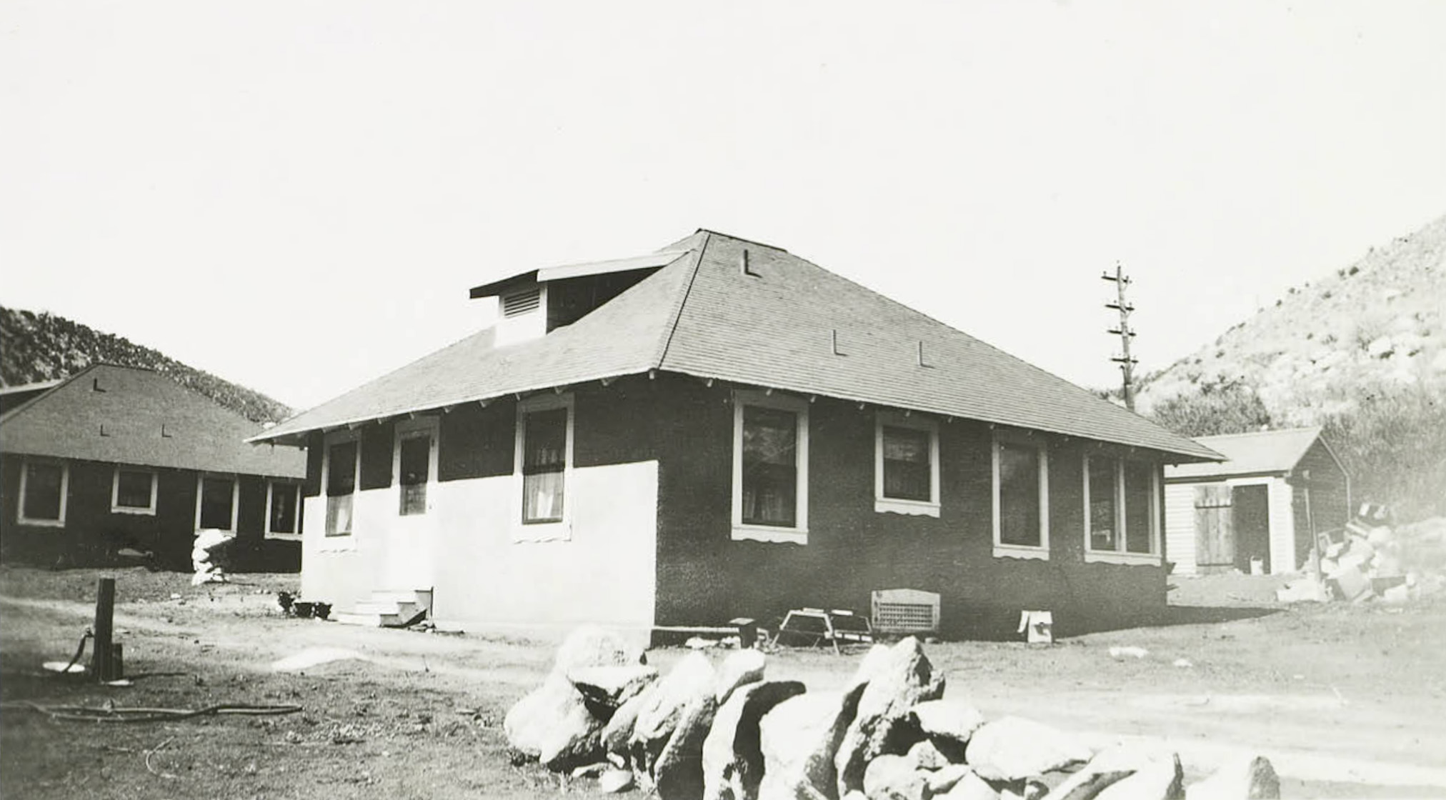
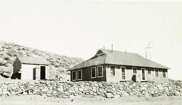
 Operators's cottages - Lundy Plant |
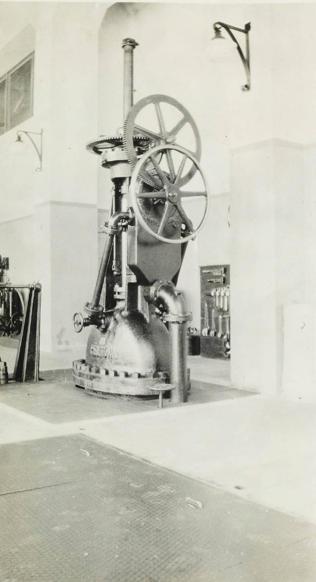 Valve in the Lundy Powerhouse |
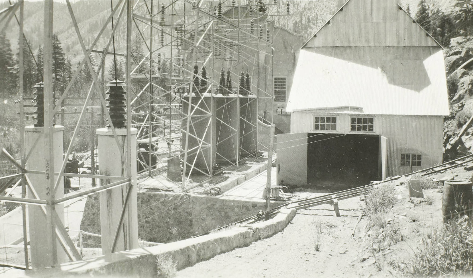
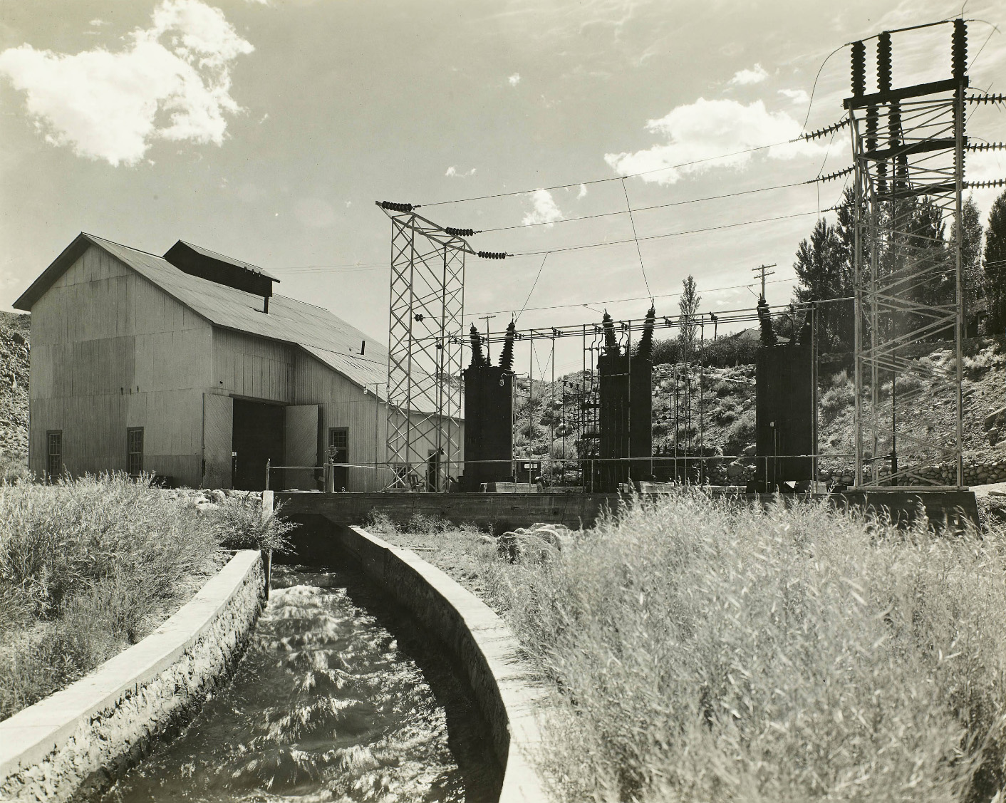
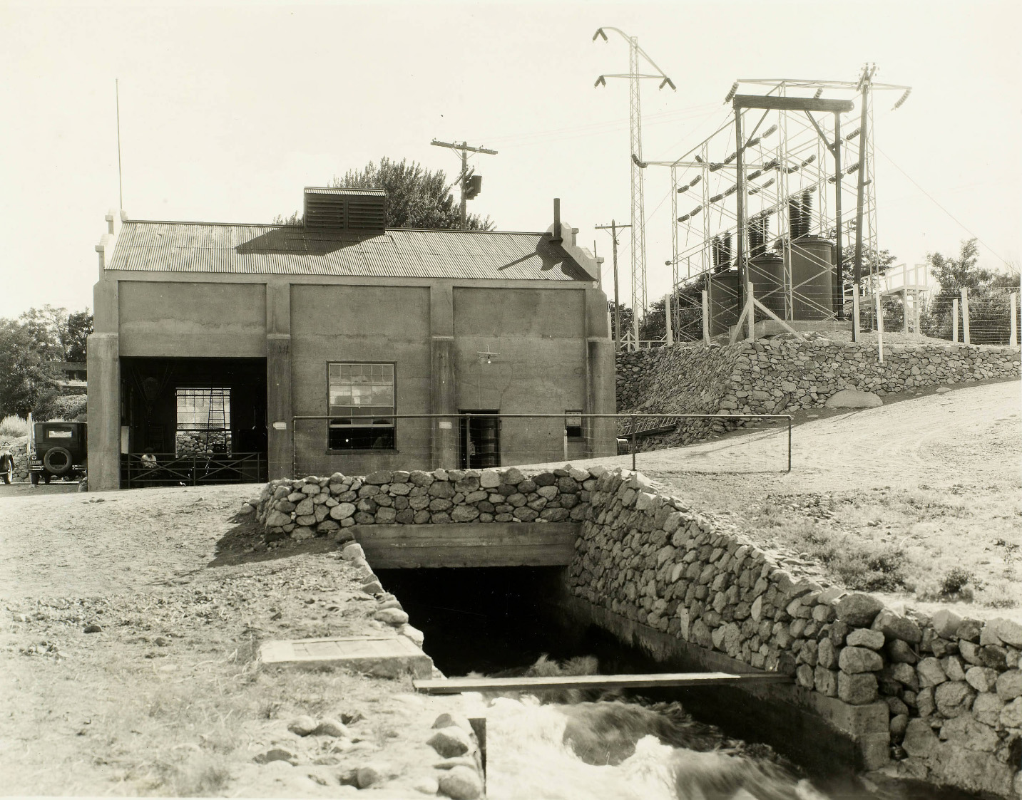
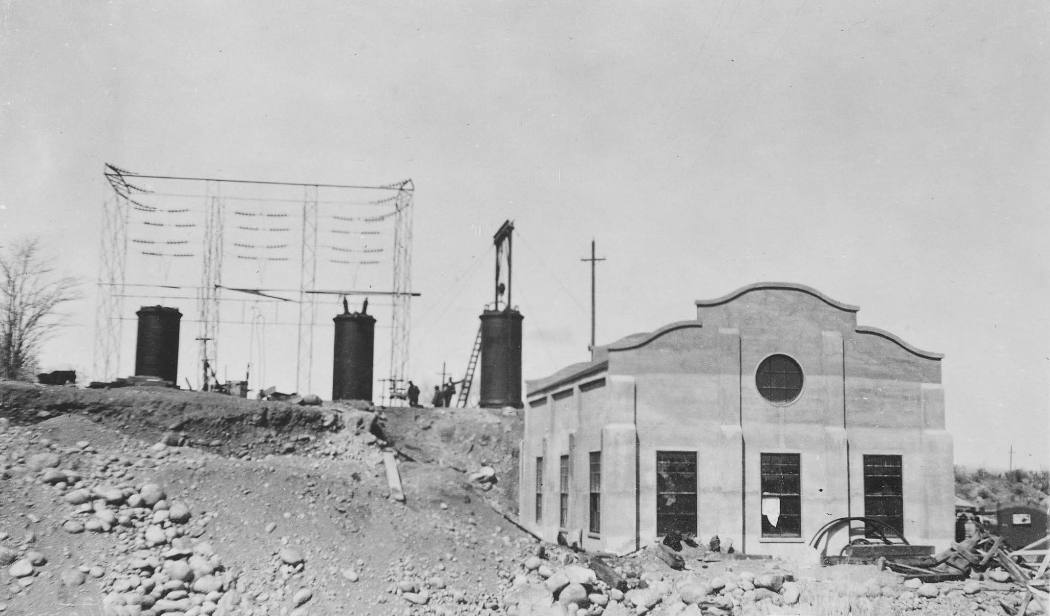
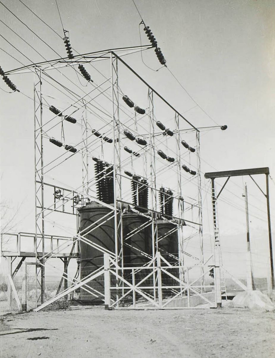
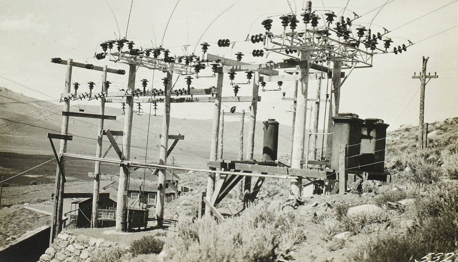 Outdoor switching station at the Lundy Plant - Terminus of Bishop-Lundy Line |
 Control Station Bowie Switch controlling the Lundy-Bishop line in the foreground. |
 Control Station |
 Control Station |
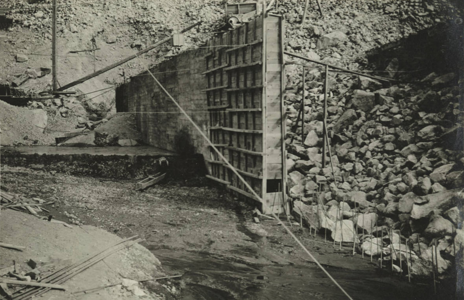
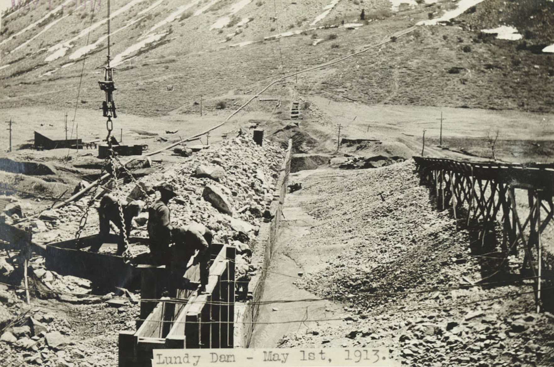
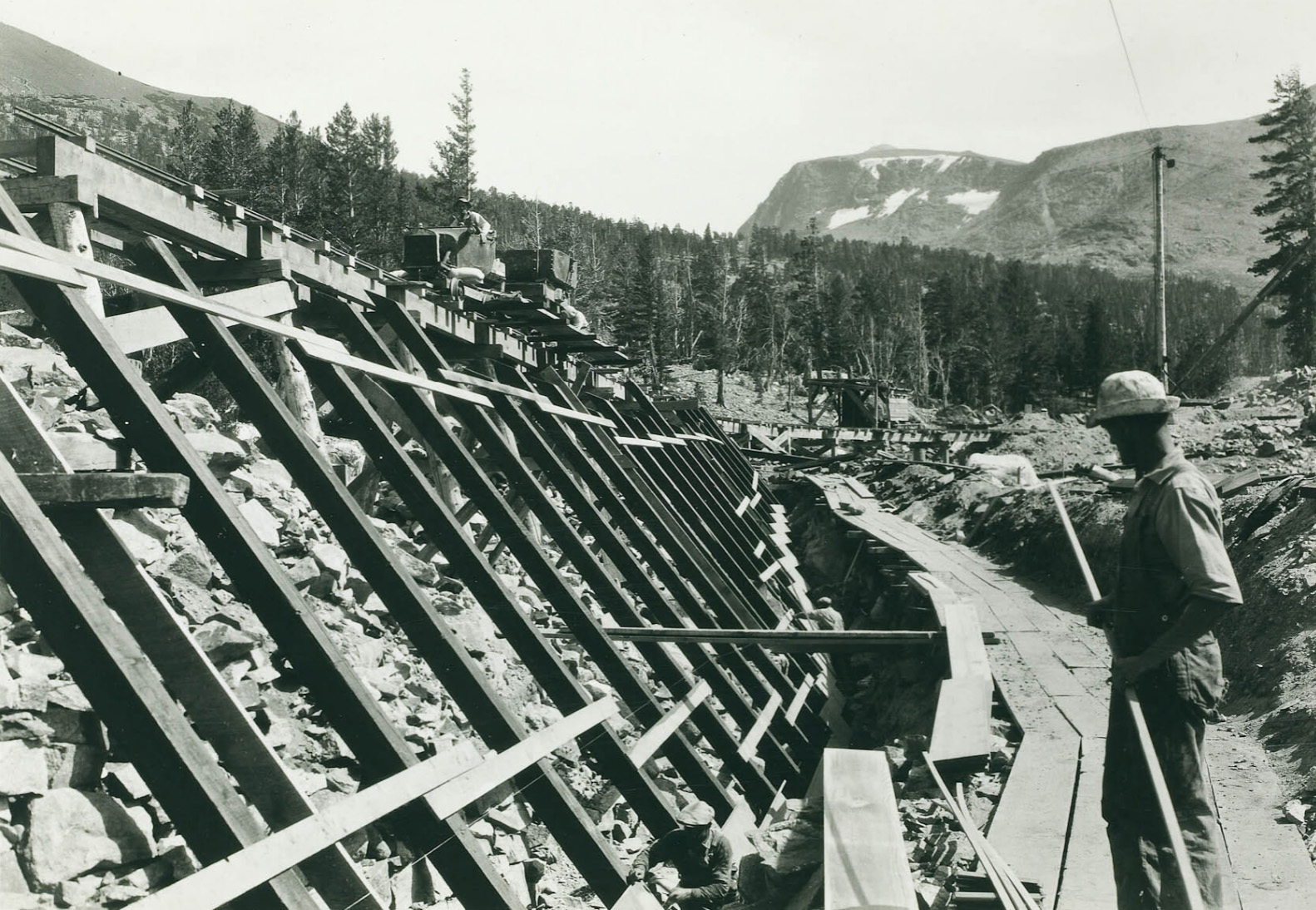
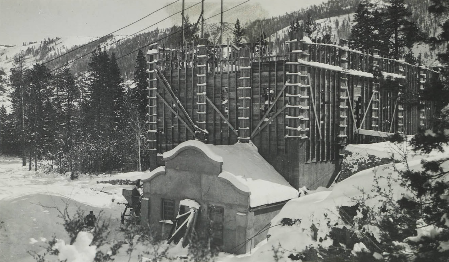
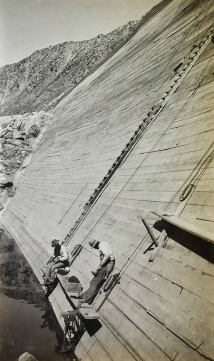
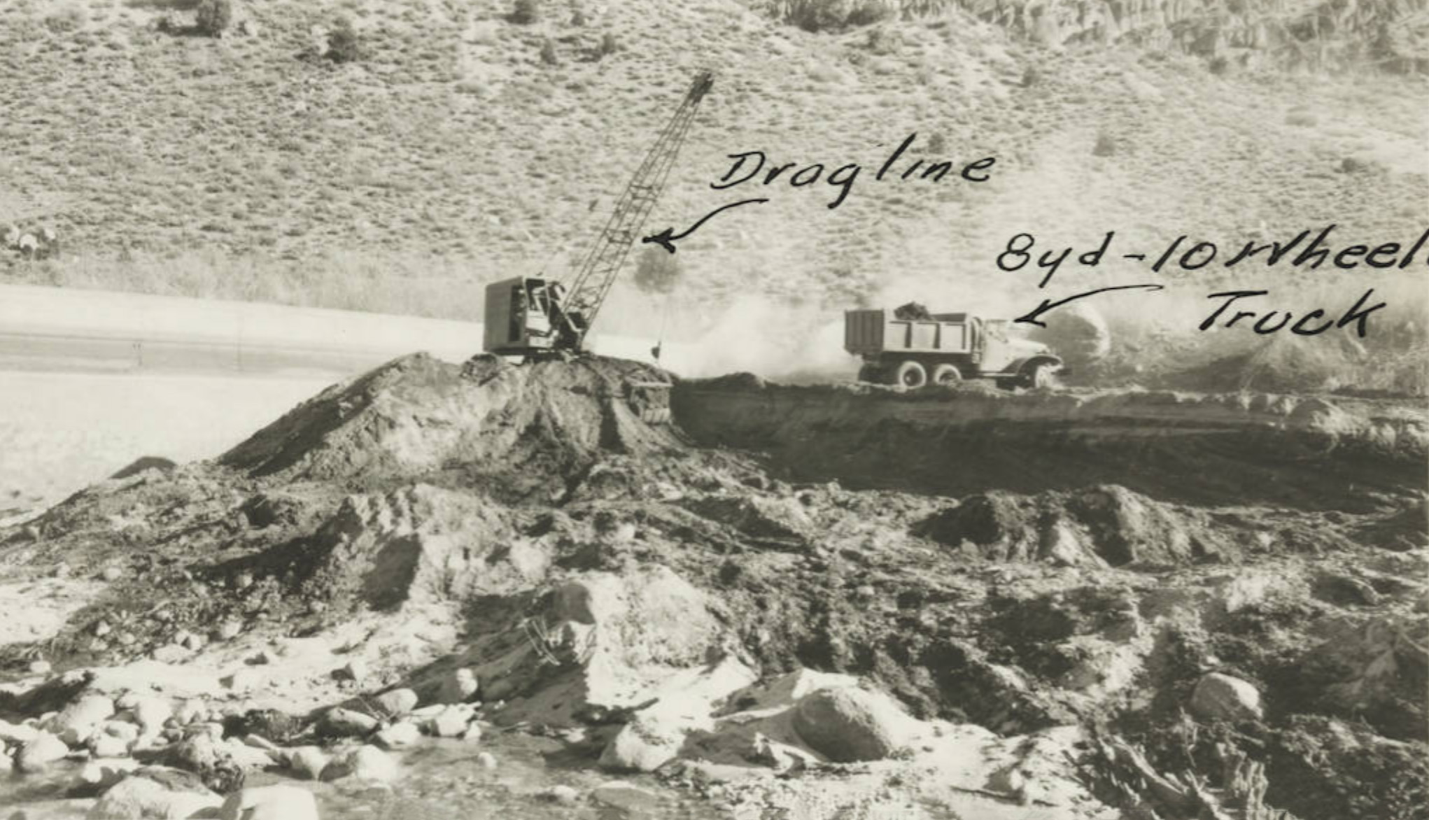
 Lundy Lake Dam construction - showing the concrete core wall and the rock fill on the lower side. |
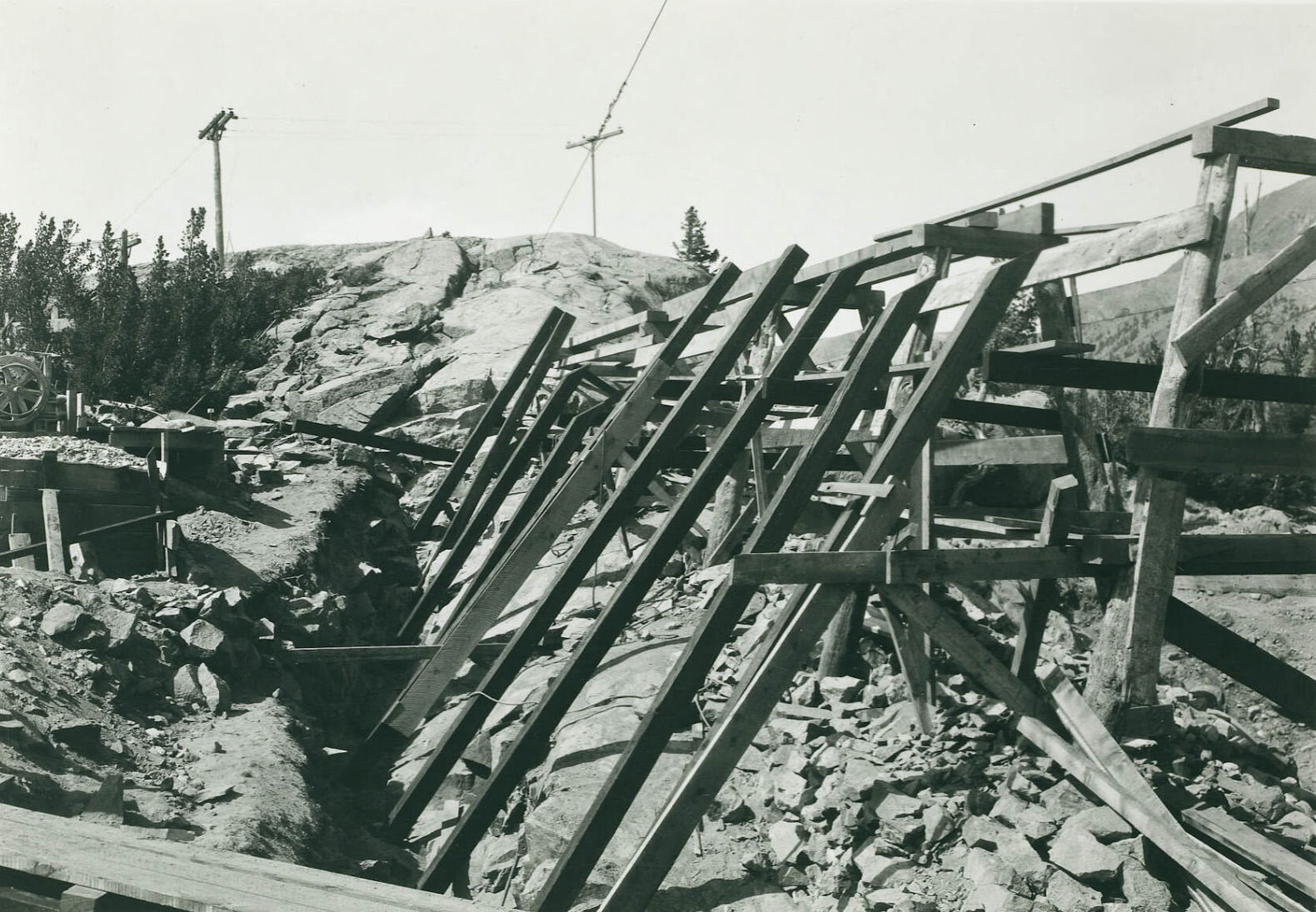
 Excavating the core wall at Lundy Lake Dam |
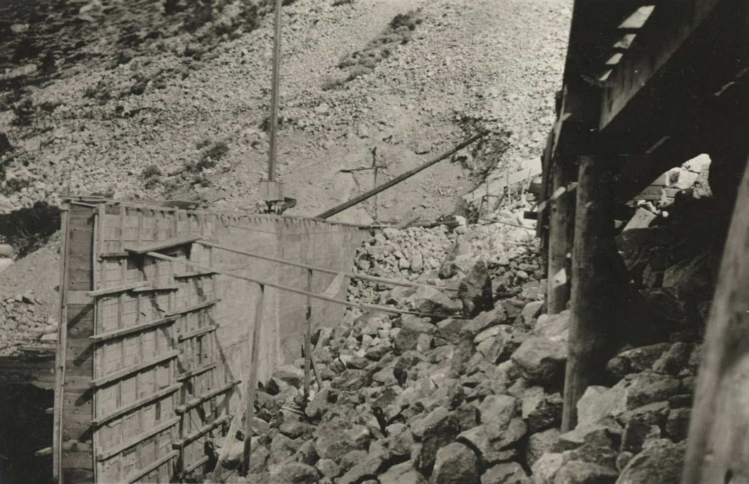
 Forms for the core wall on the Lundy Lake Dam |
 Lundy Spillway Gate |
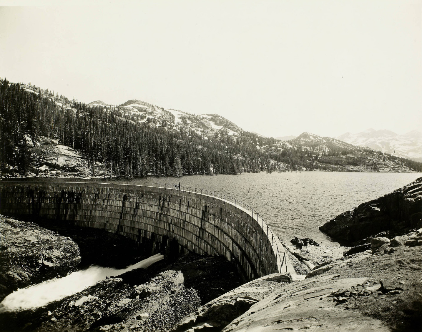
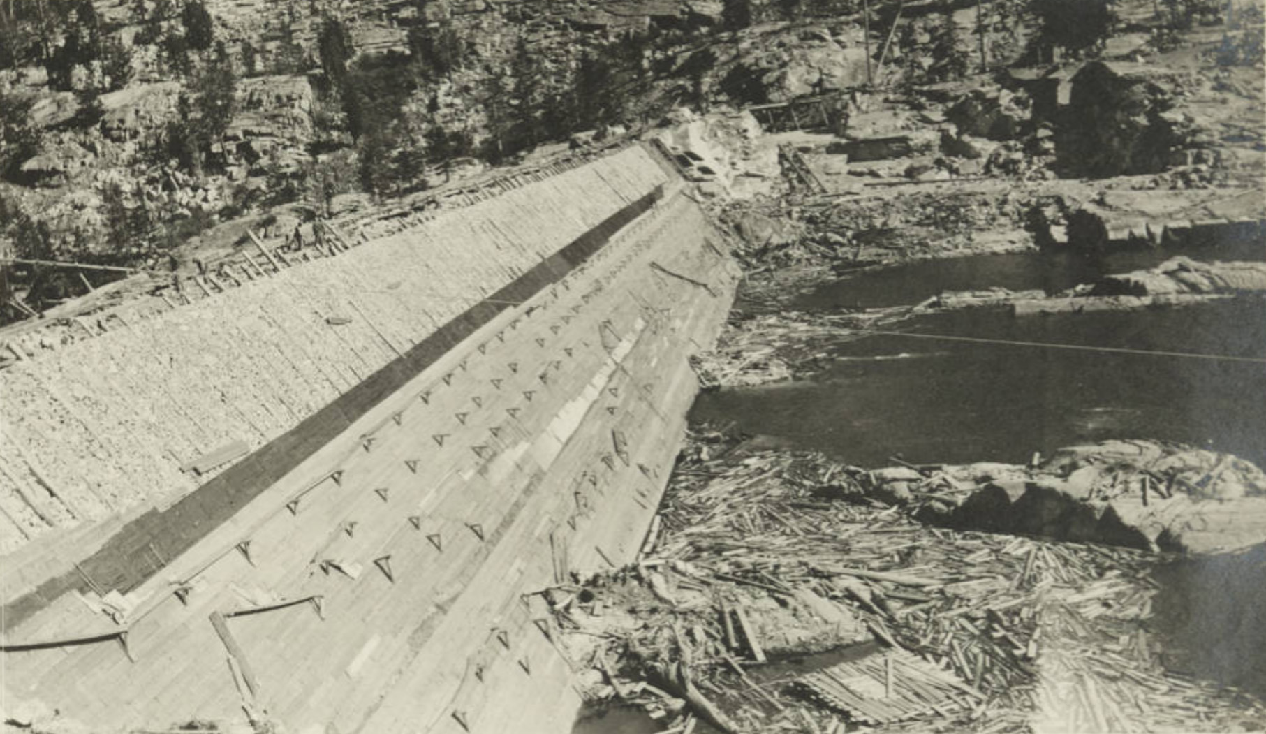
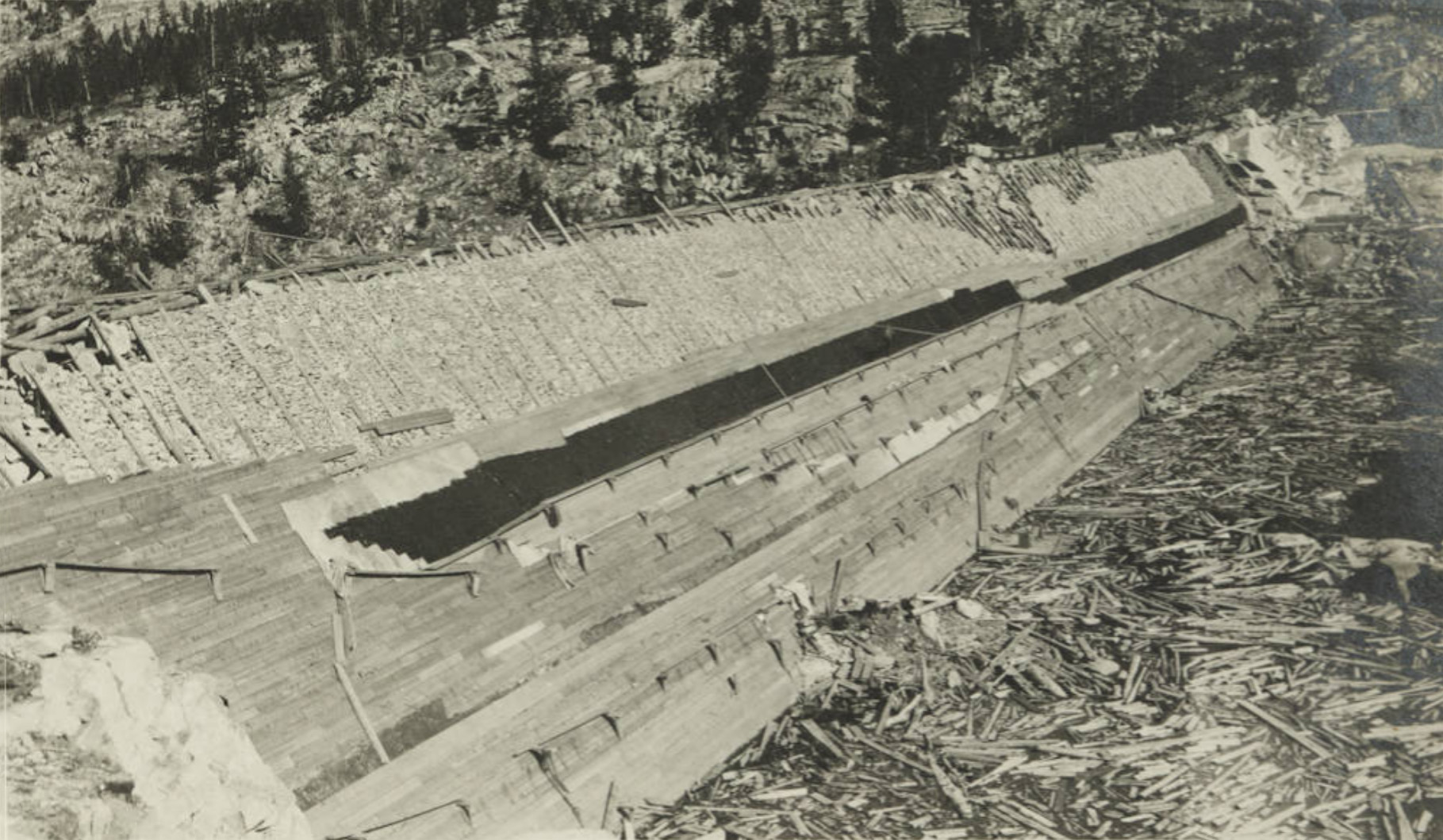
 Lundy Lake Dam showing part of the downstream side of the core wall and back fill. |
 Lundy Lake Dam showing part of the upstream side of the core wall and back fill. |
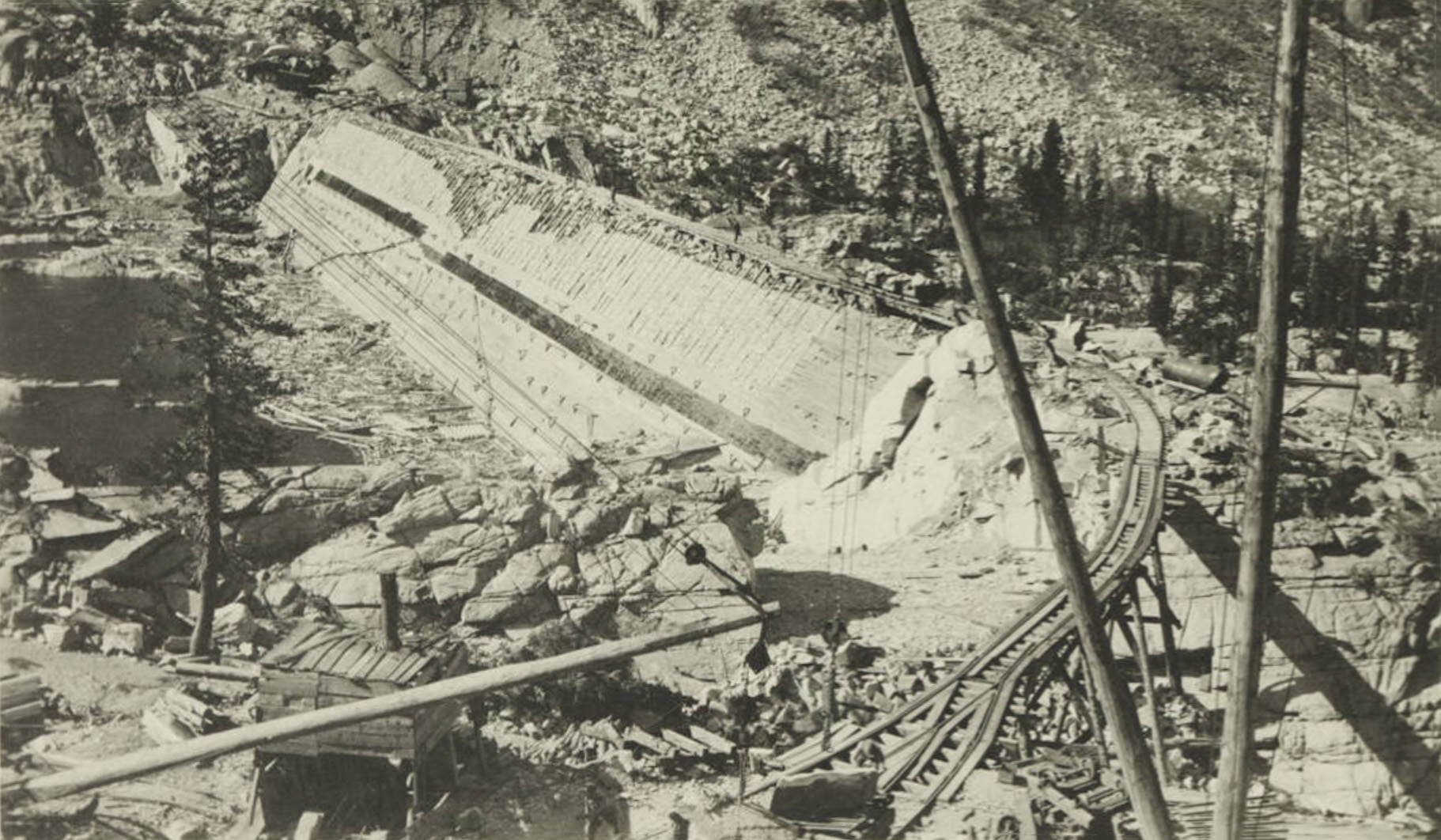
 Lundy Dam construction |
 Lundy Dam construction |
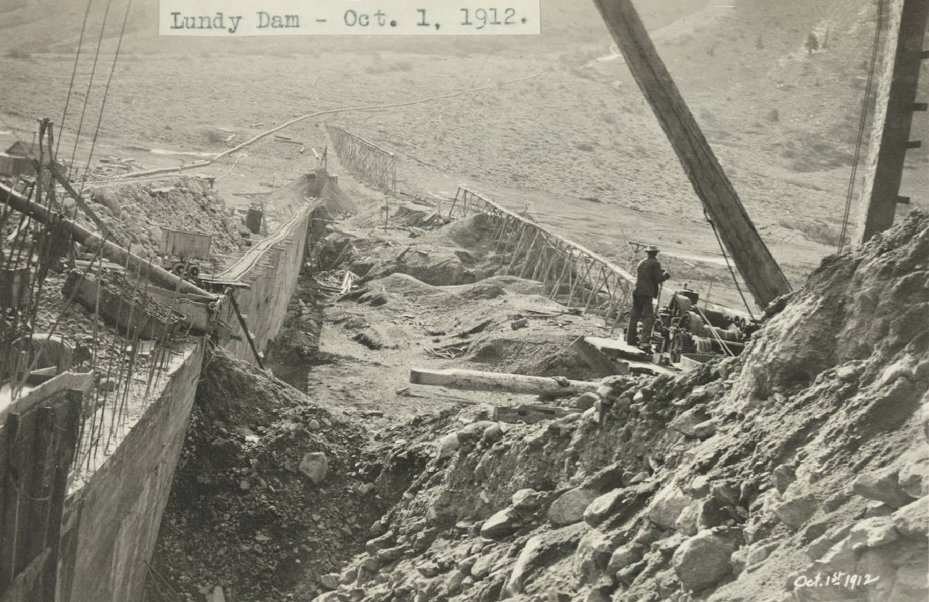
 Lundy Dam construction |
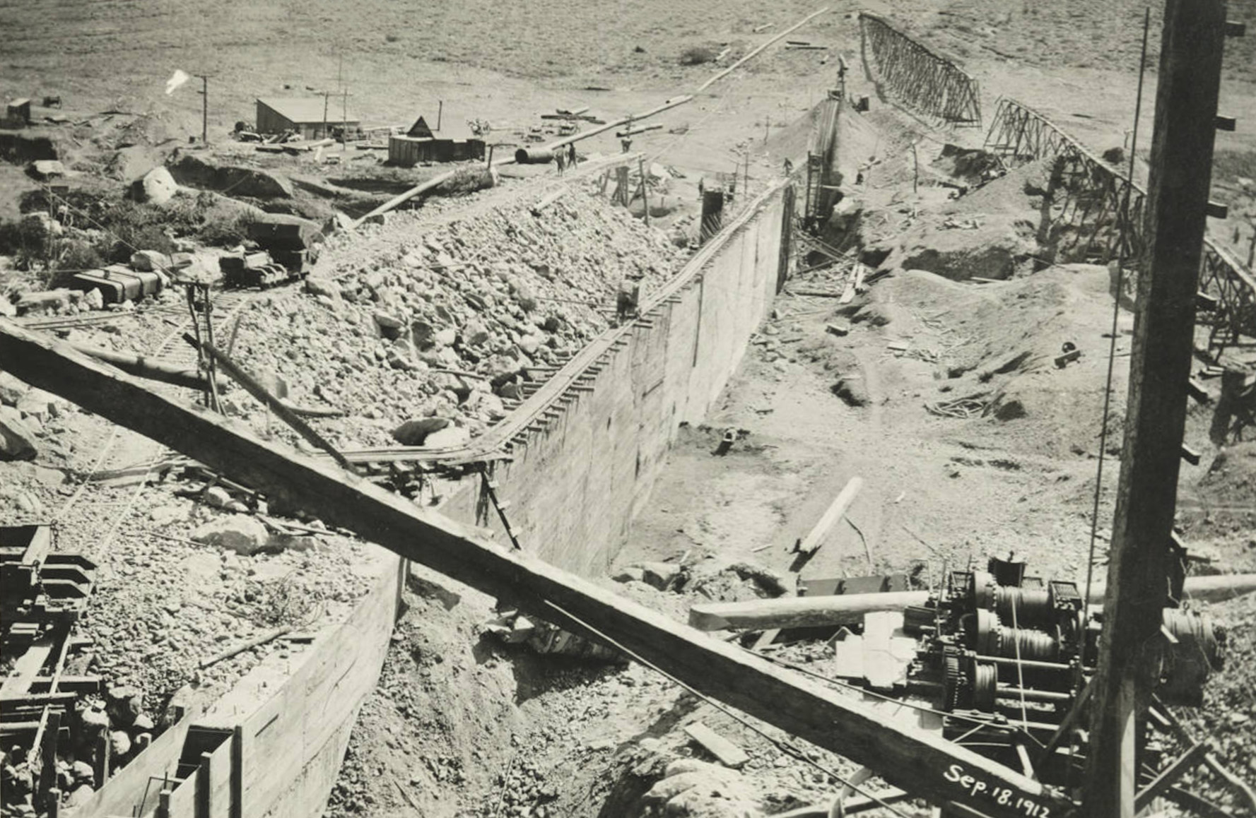
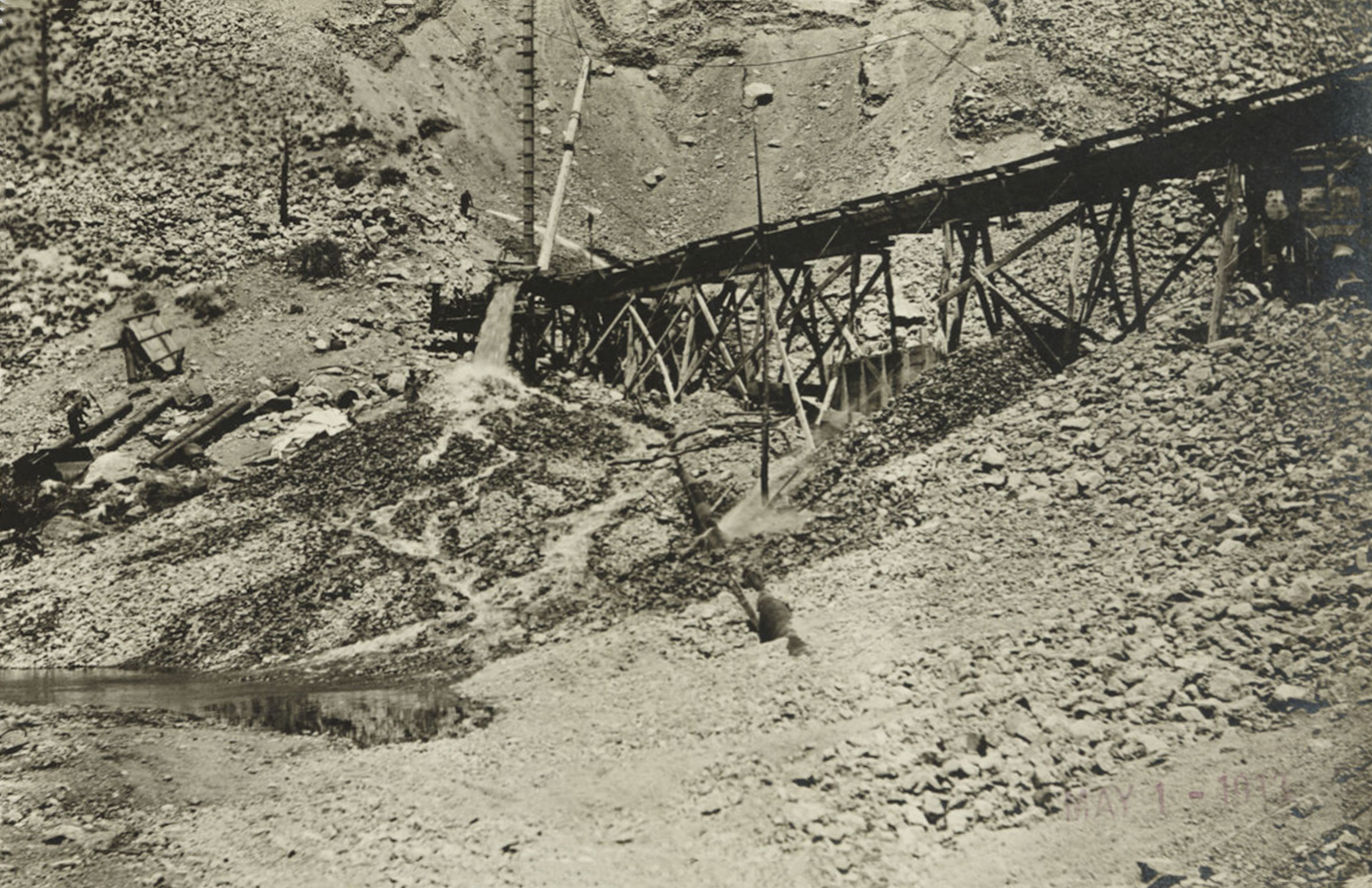 Lundy Dam construction |
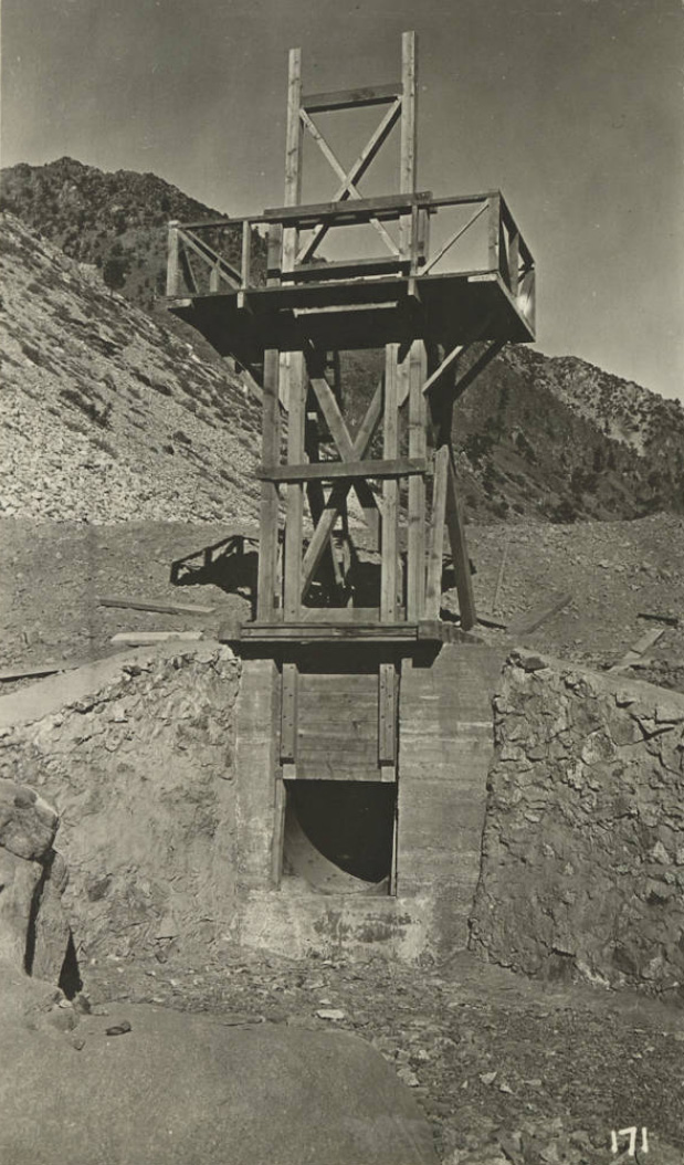
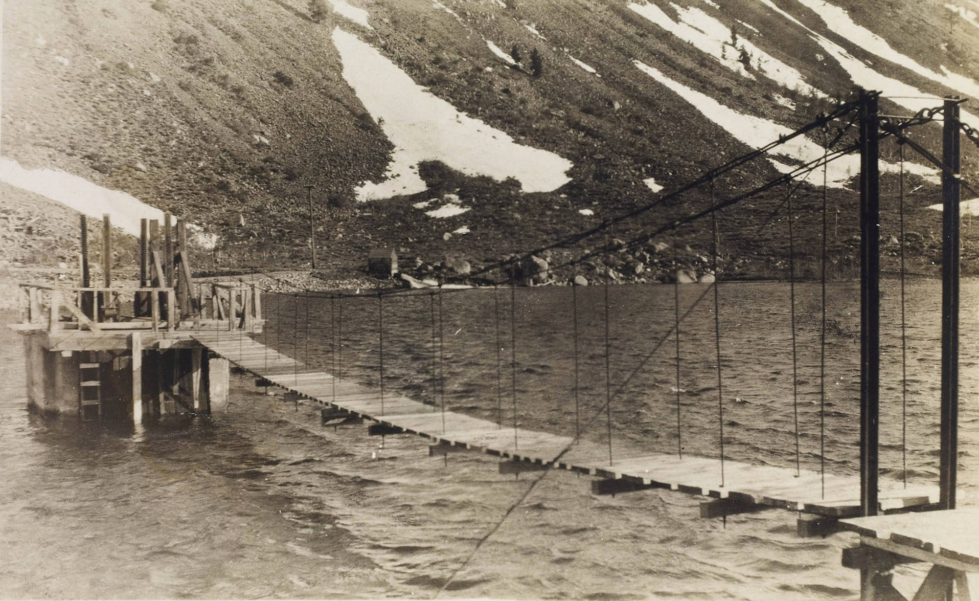
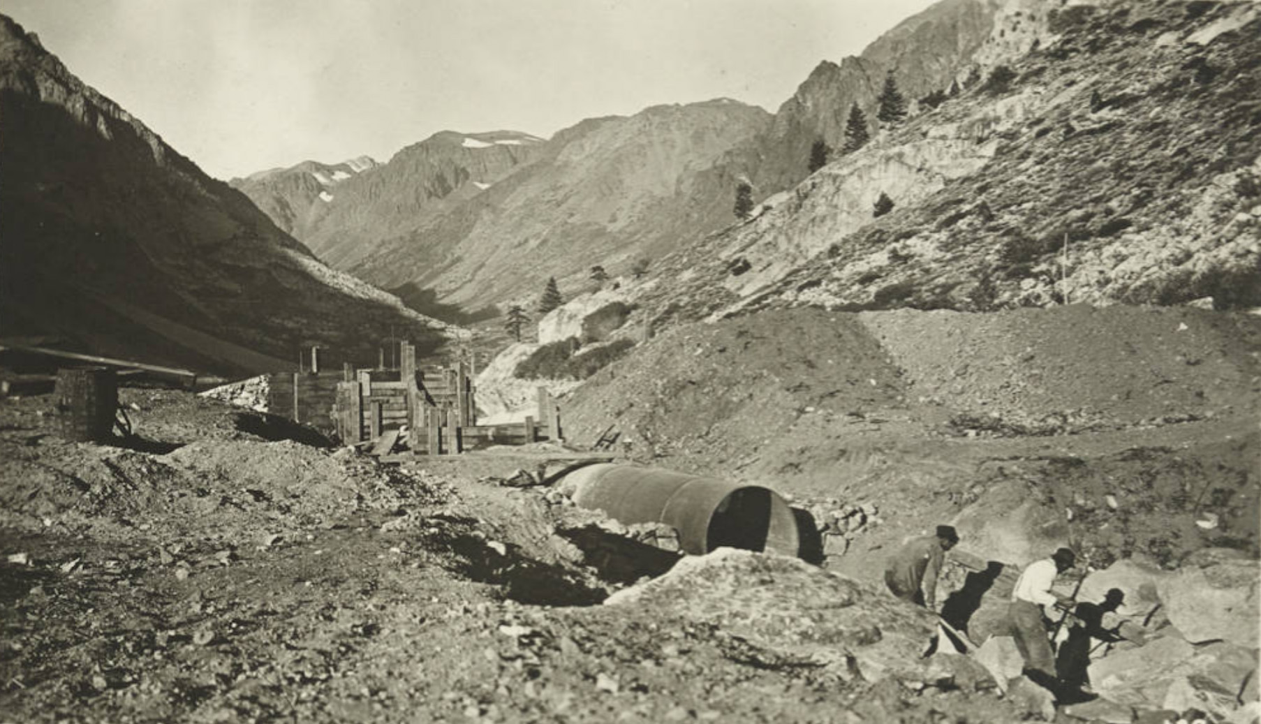 Spillway Pipe - Lundy Dam |
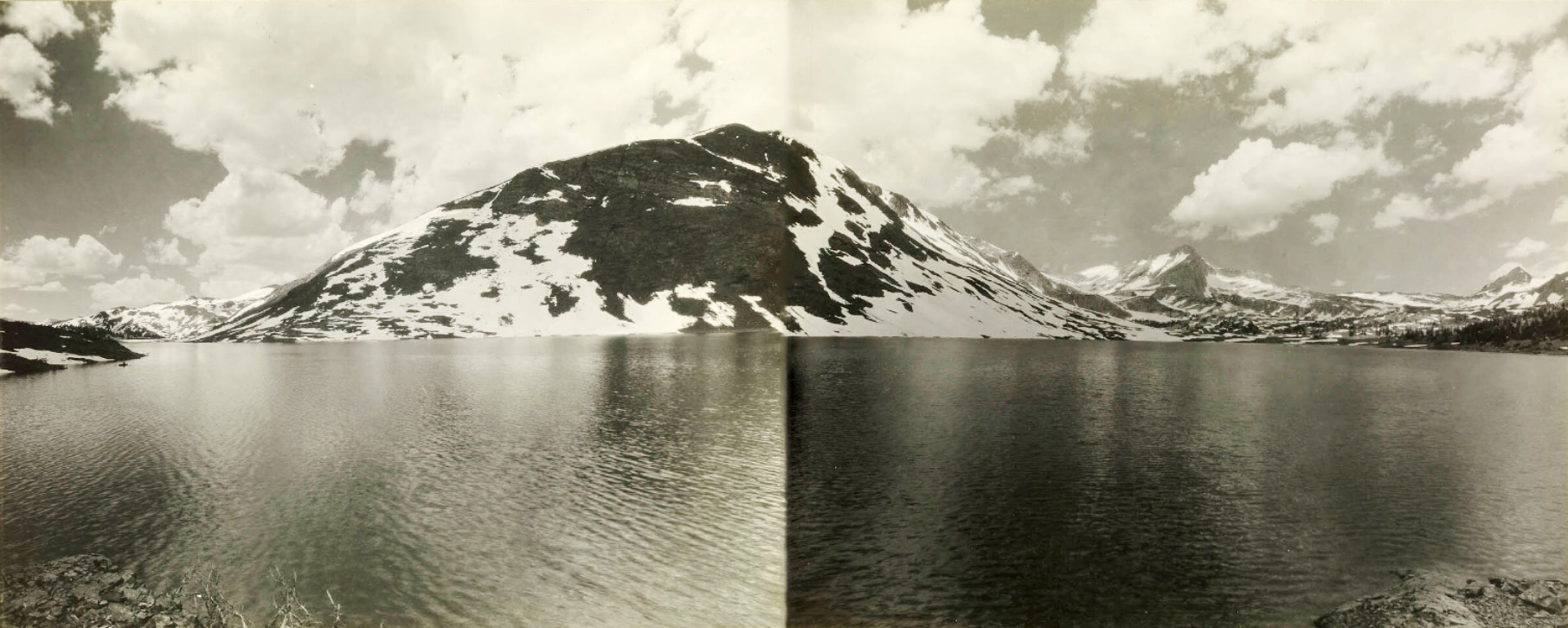
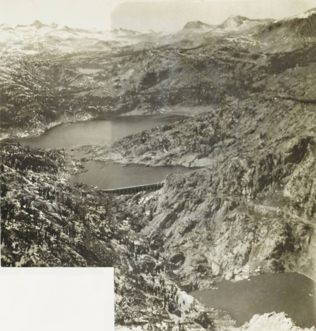
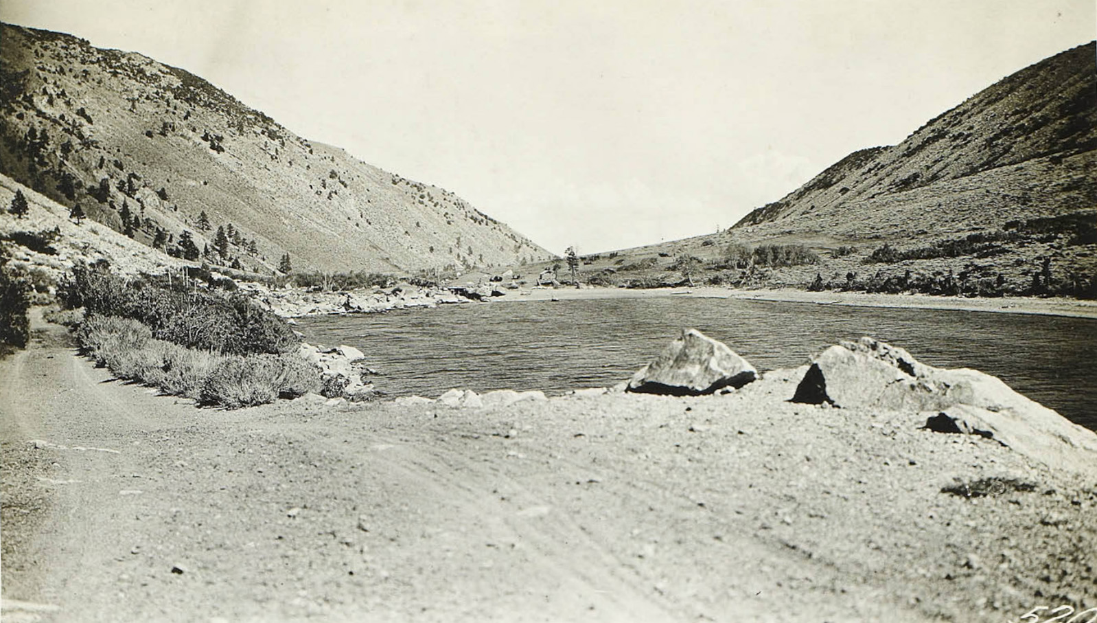 Lundy Lake looking towards the dam |
 Wood stave flow line to the Lundy plant |
 Covered wood stave flow line to the Lundy plant |
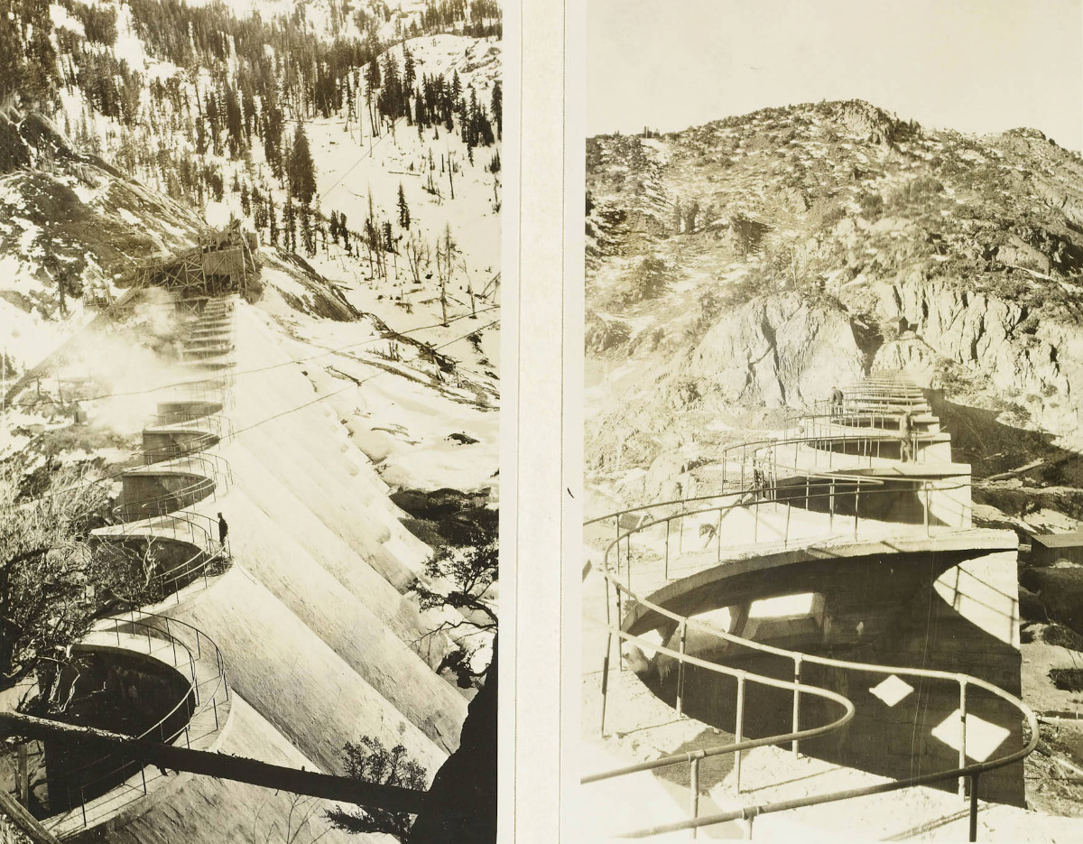
 Terminus of the wood stave pipe and the head of the steel pressure pipe, showing the pipe laid in the ground on an angle. |
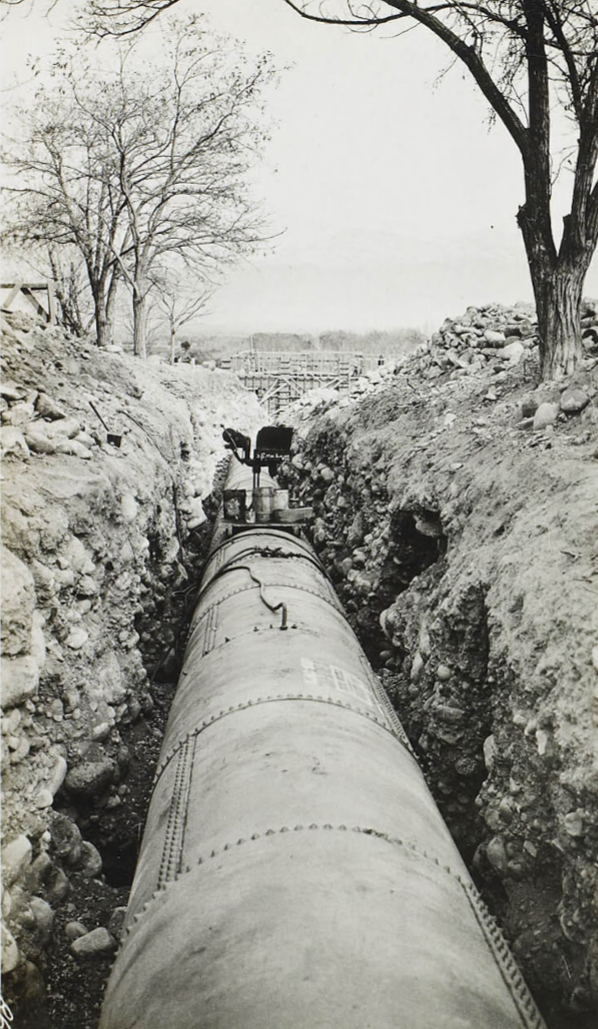
 Steel pressure pipe leading to the Lundy Powerhouse before covering. |
 Steel pipeline being layed towards the Lundy Powerhouse |
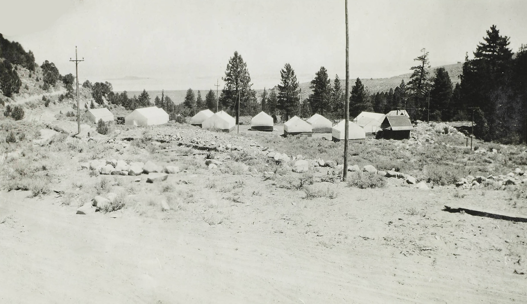
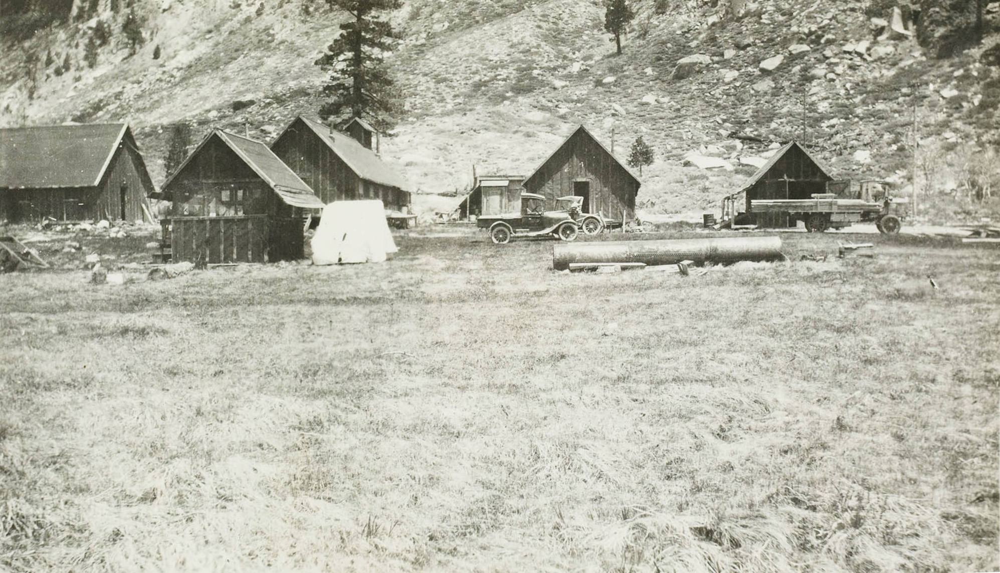
 Leevining Creek Camp |
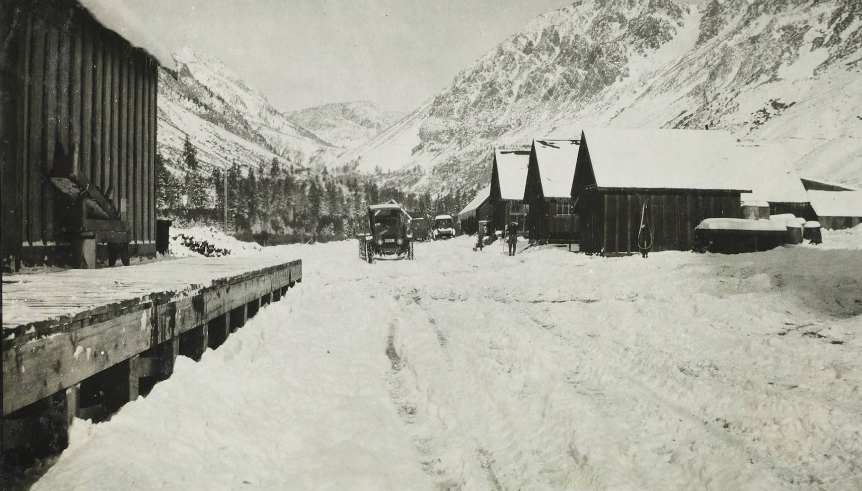 Leevining Creek Camp |
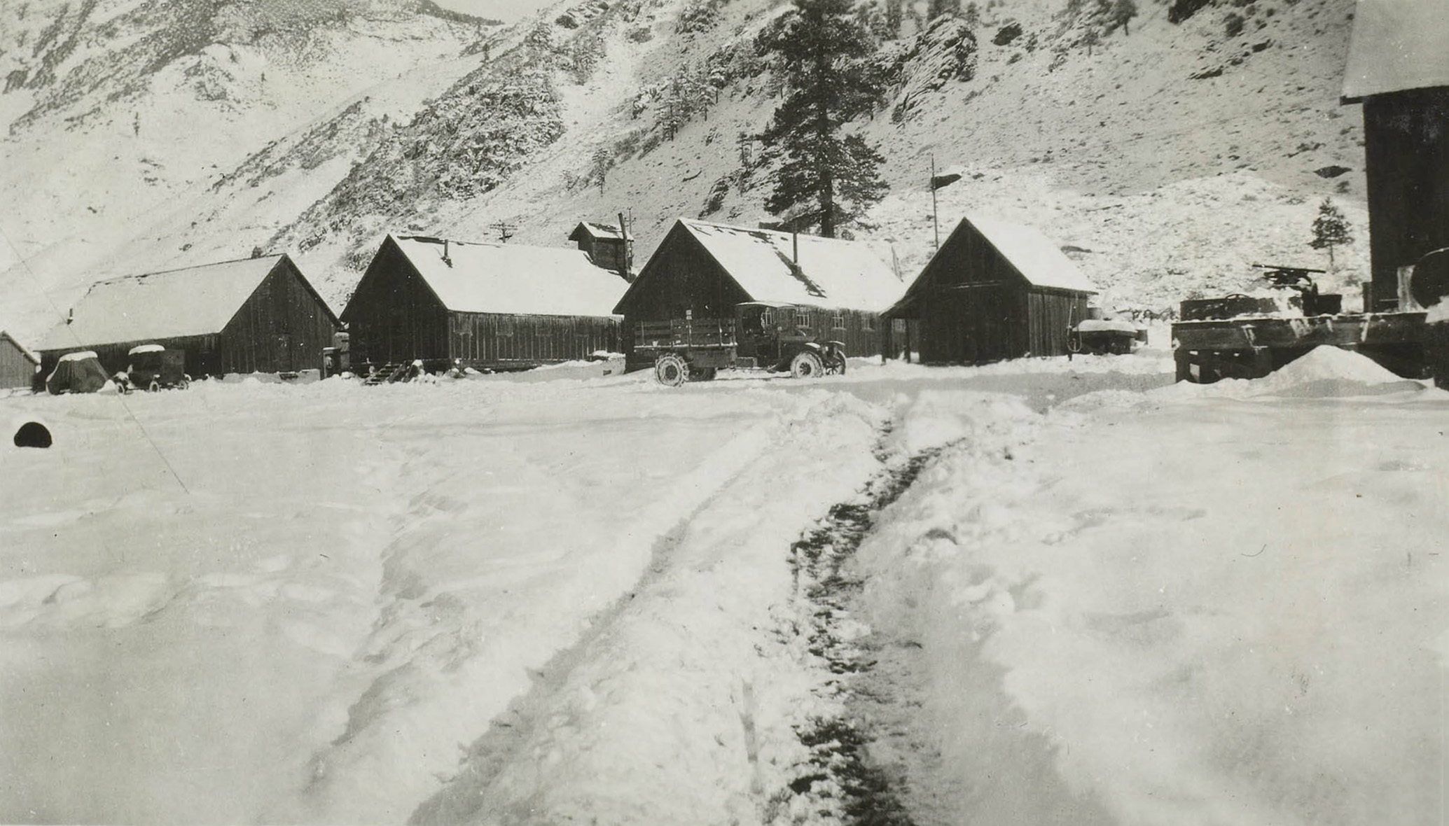 Leevining Creek Camp |
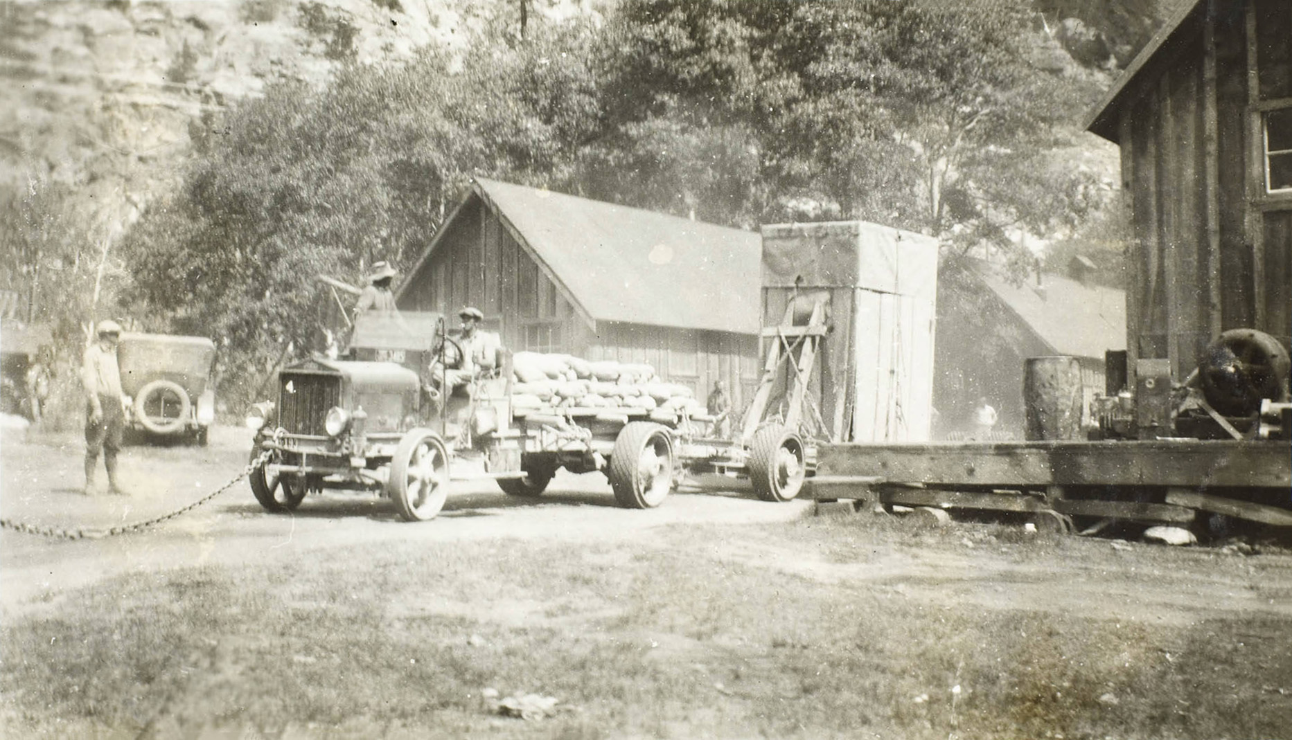
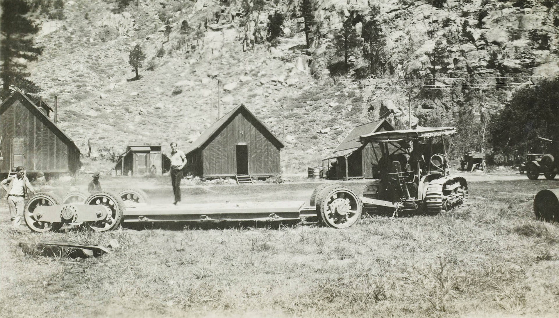
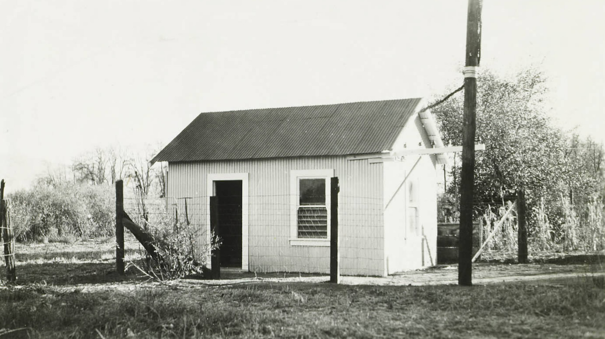
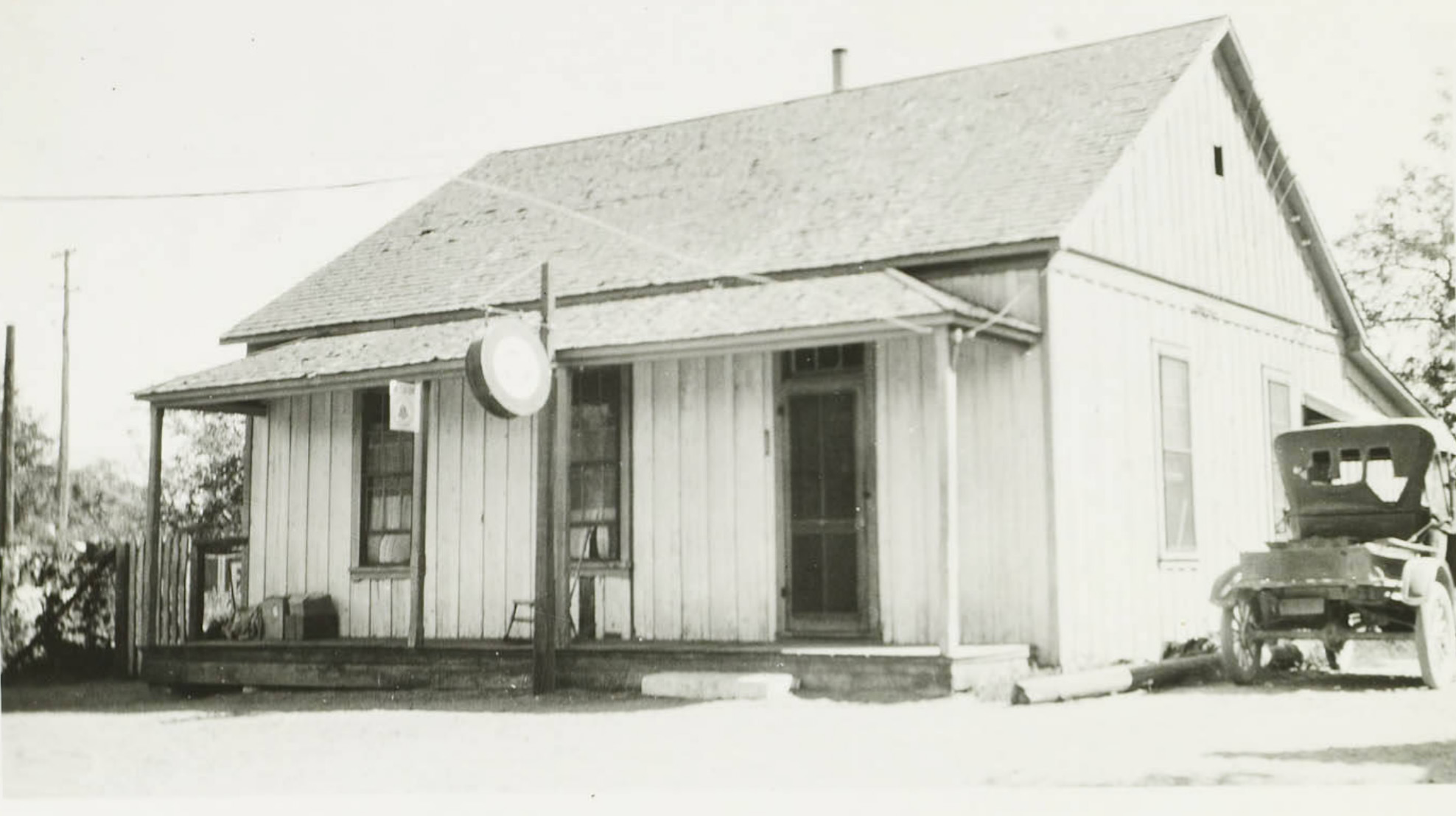
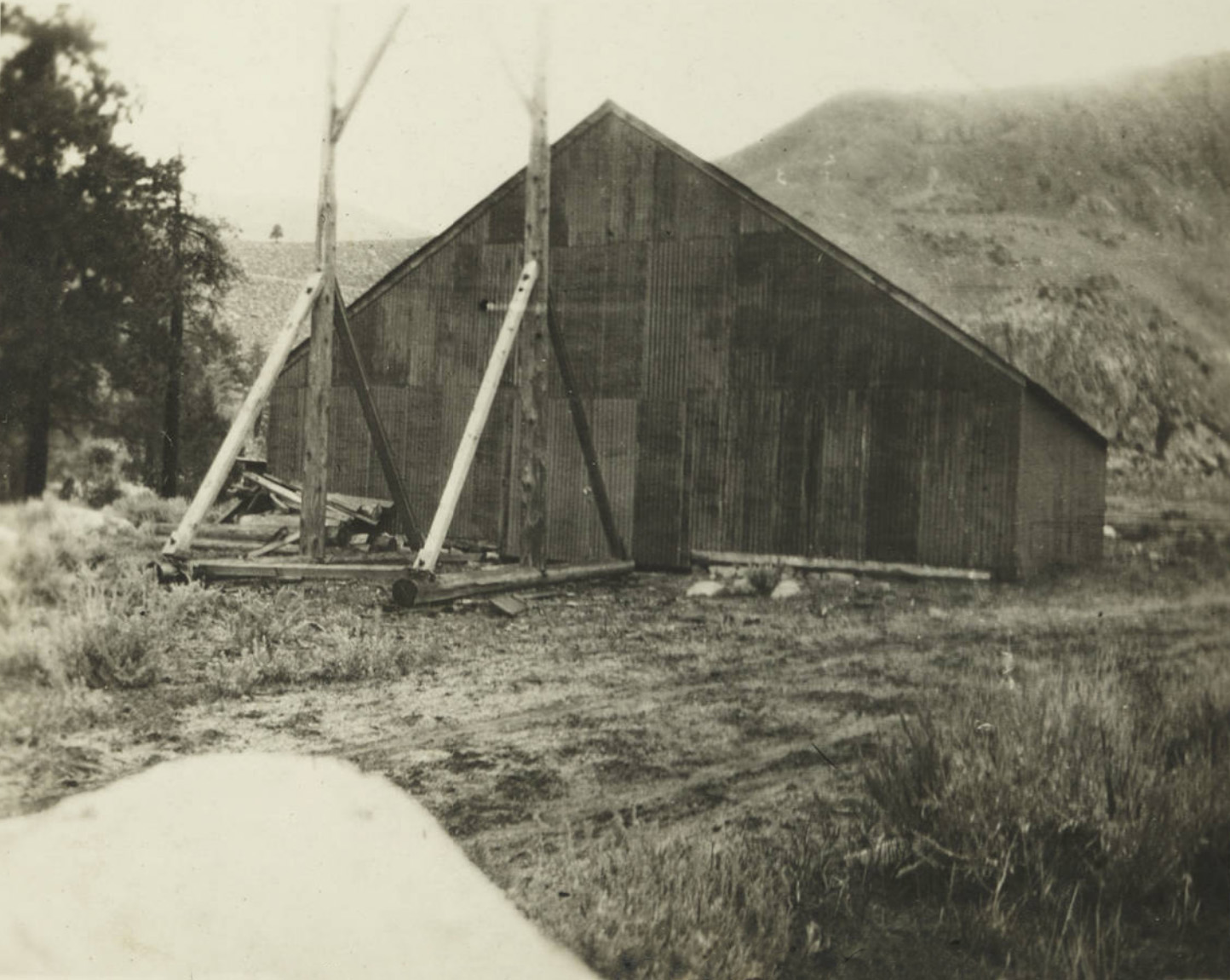
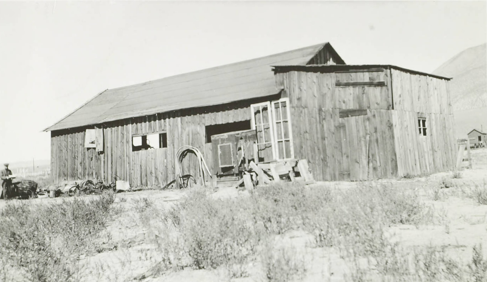 Benton Station tractor shed. |
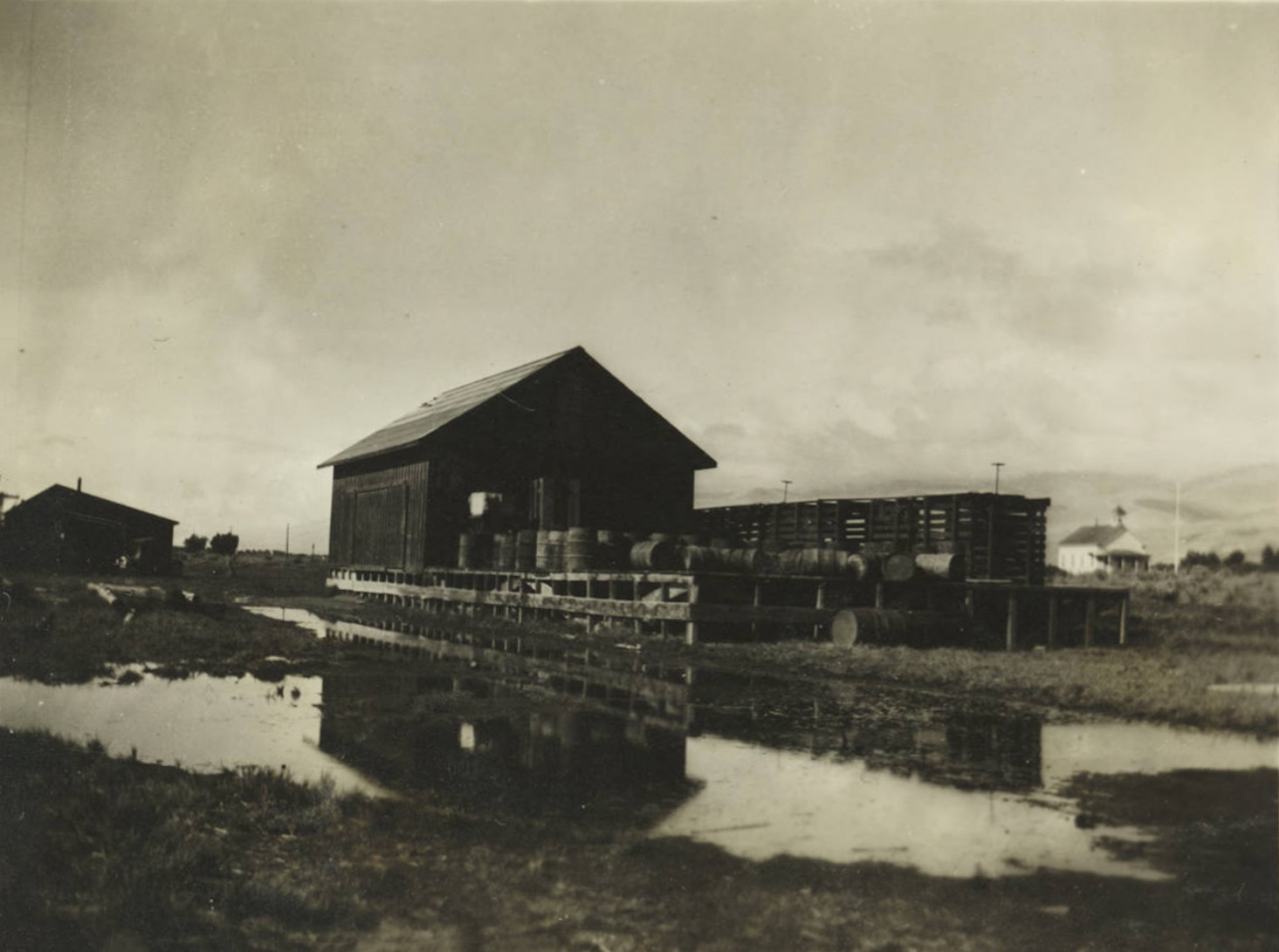
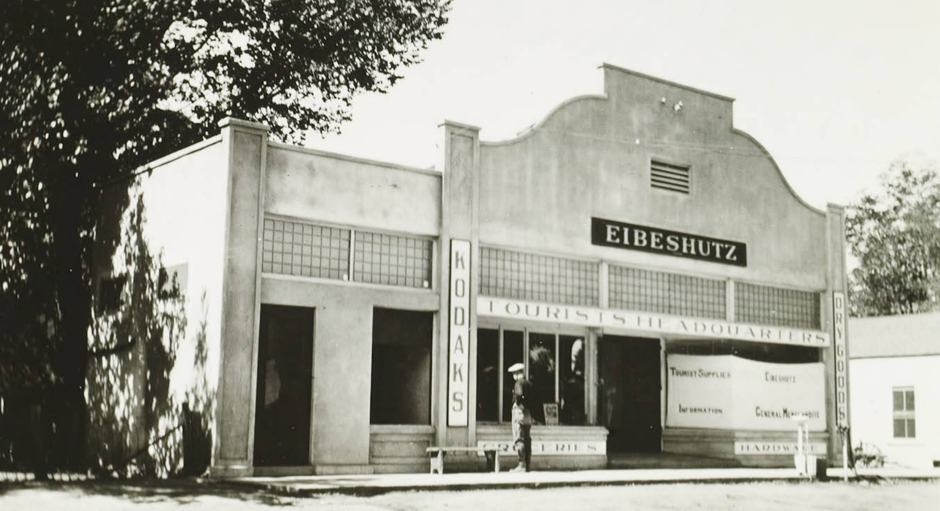
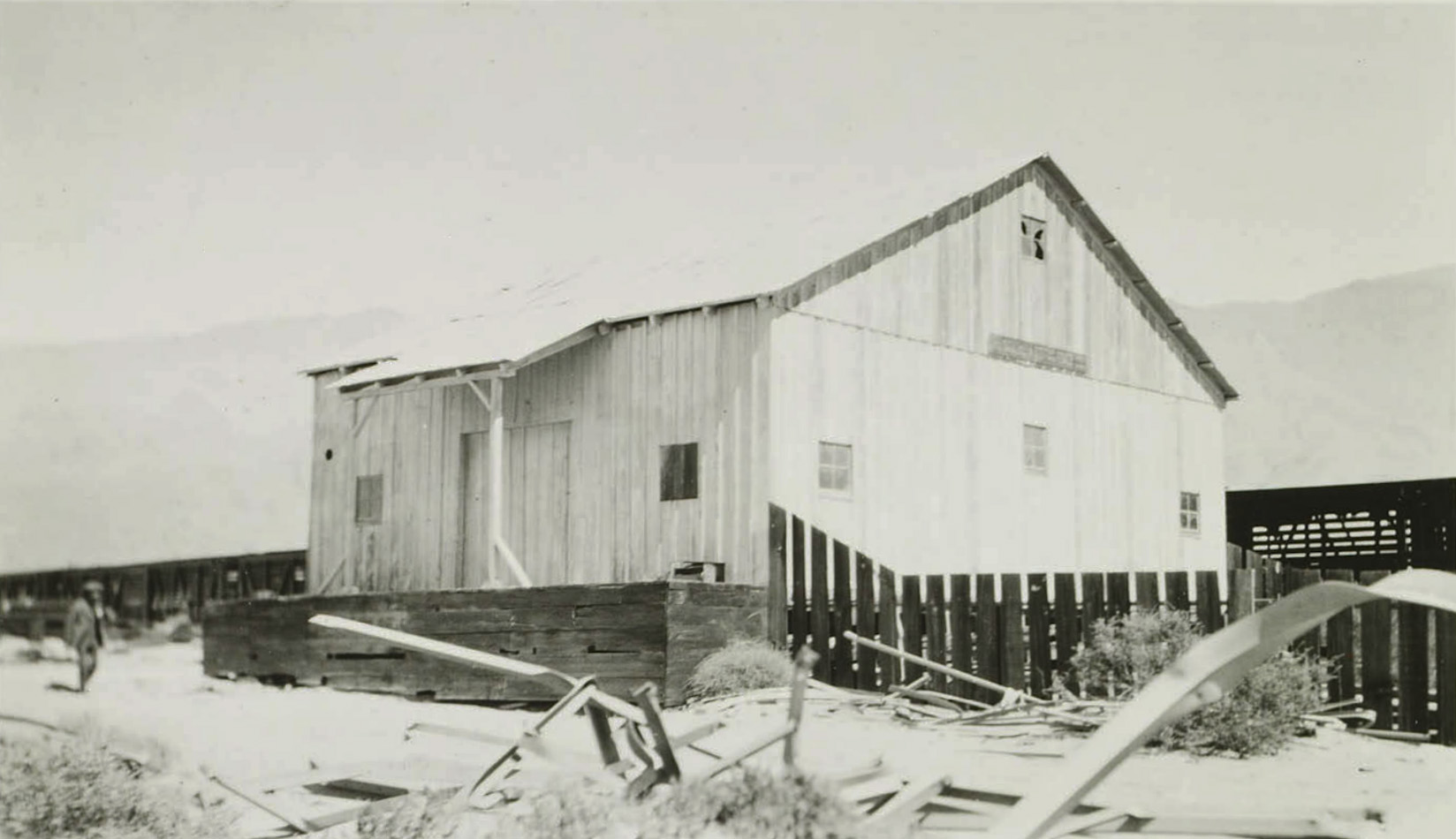
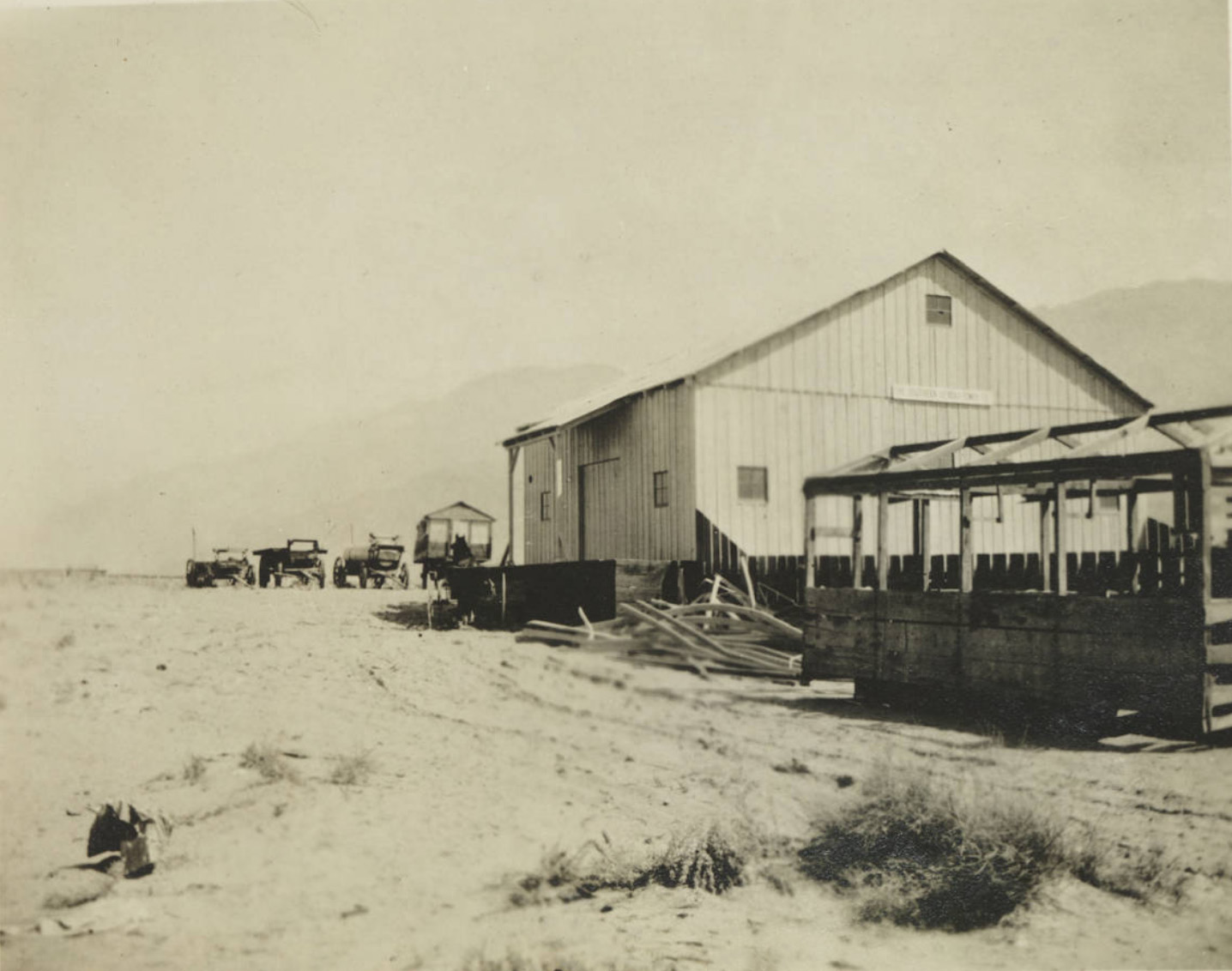
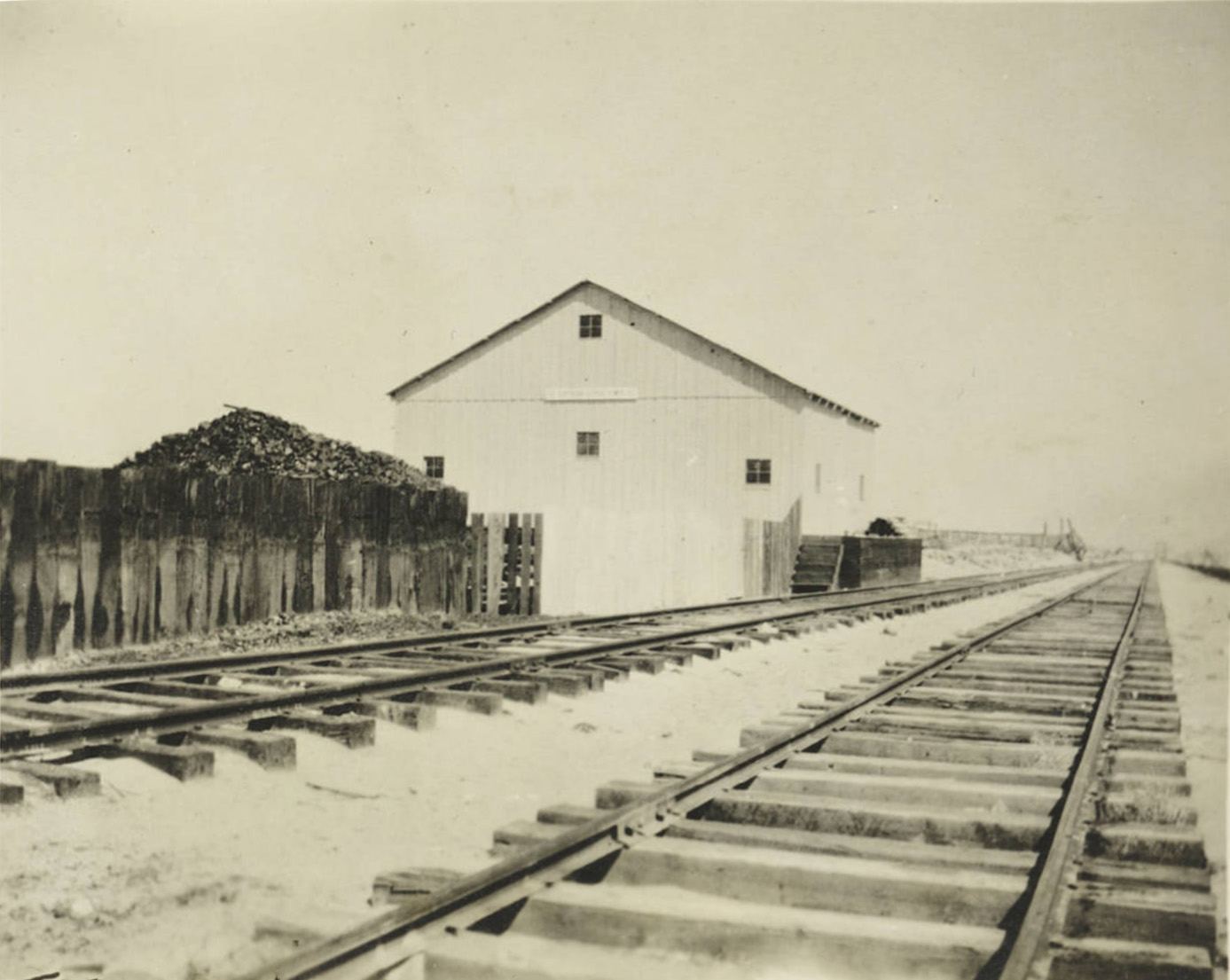
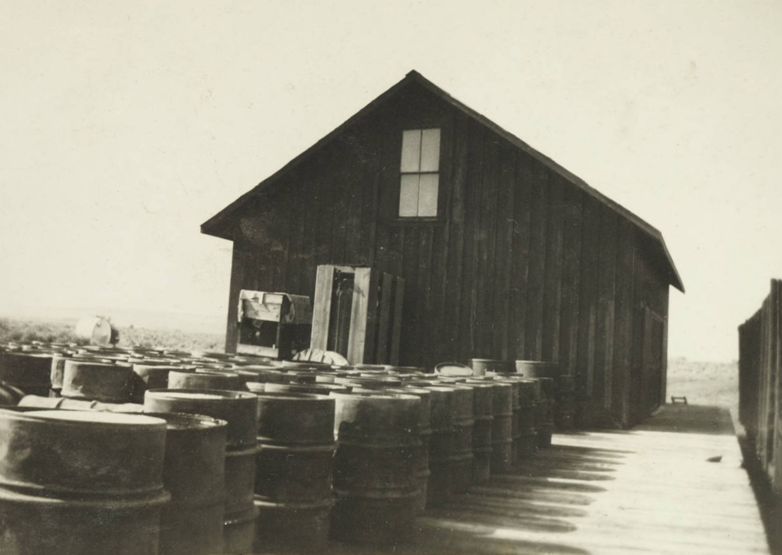
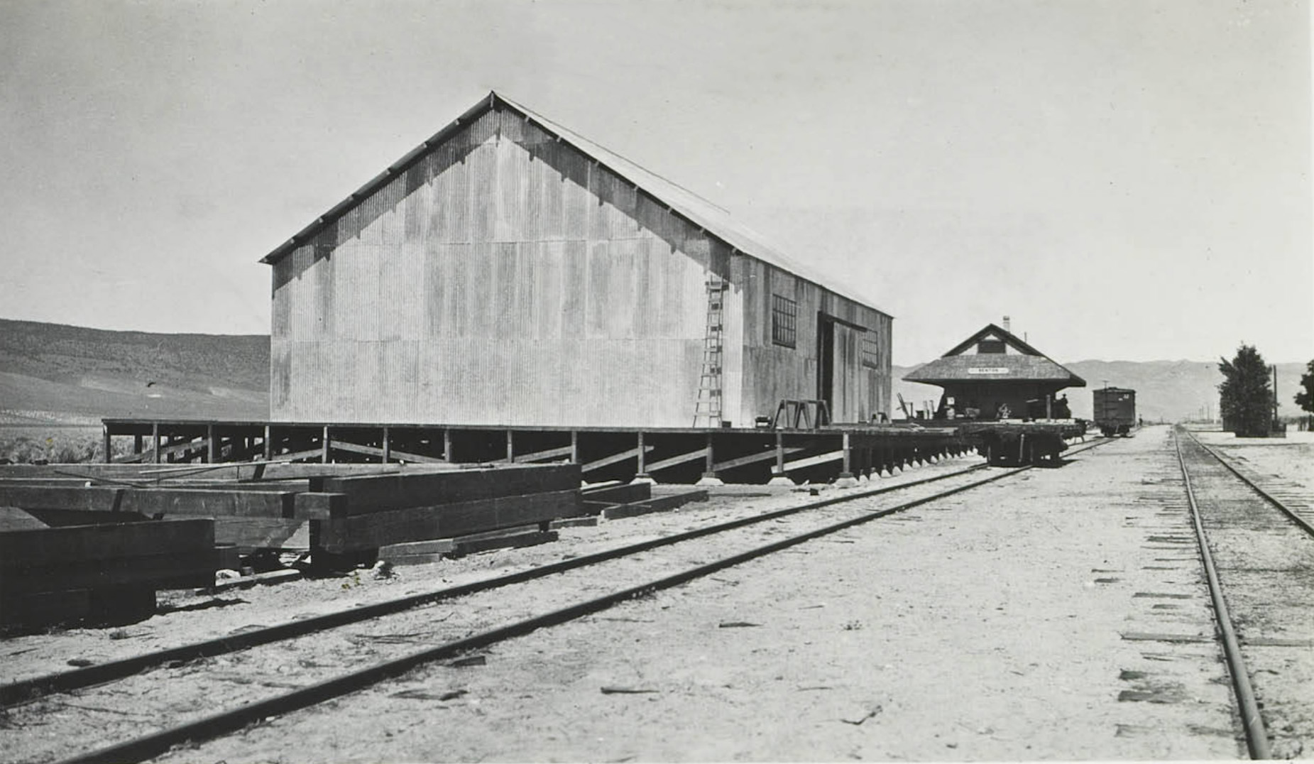 Warehouse in Benton along the SPNG where supplies were stored. |


Historic Overview of the Rush Creek and Lee Vining Creek Hydroelectric Projects
by Valarie H. Diamond and Robert A. Hicks
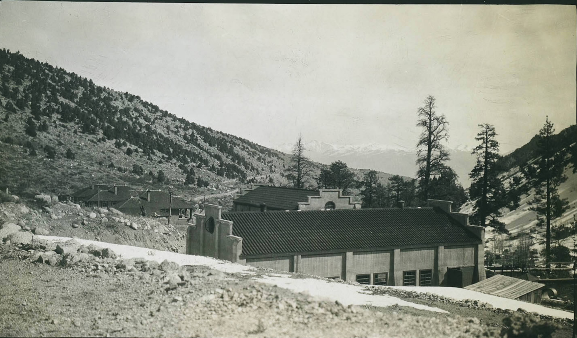
Rush Creek Powerhouse Silver Lake, Agnew Lake, Gem Lake, Grant Lake |
|
 Water from Rush Meadows, Gem and Agnew Reservoirs is supplied through 4,296' of steel pipe line from Gem Lake to Agnew Junction, from which point two steel pressure lines, 4,261' and 4,280', respectively, deliver water to the powerhouse. The generating equipment consists of two horizontal impulse water wheels with combined capacity of 16,000 horsepower connected to two alternating current generators with a combined capacity of 11,250 Kv-a. Power tnerated at the Rush Creek Plant is transmitted to a Control Station 54 miles. |
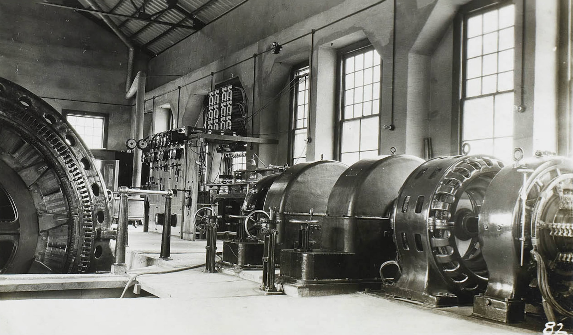
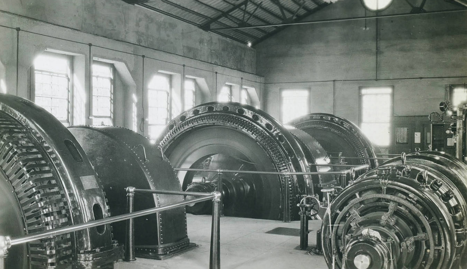
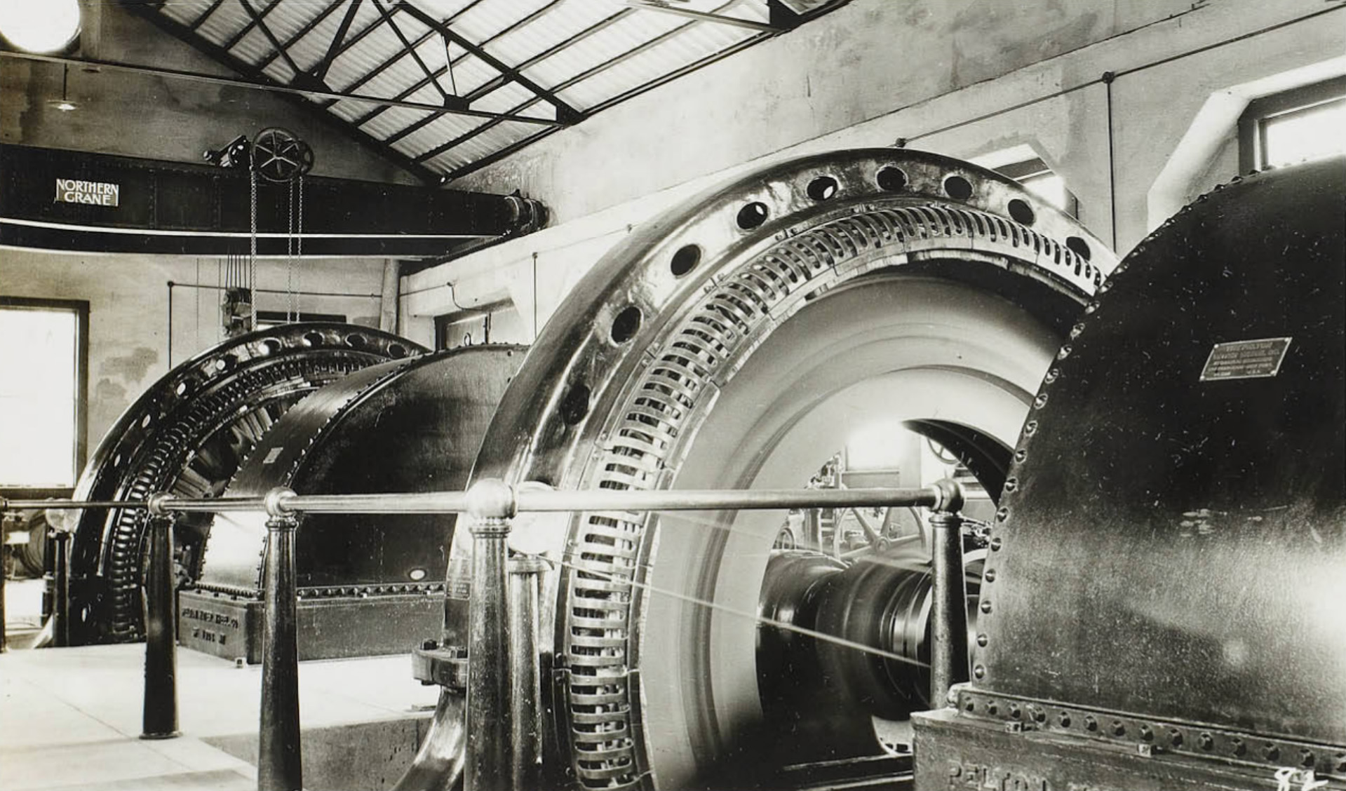
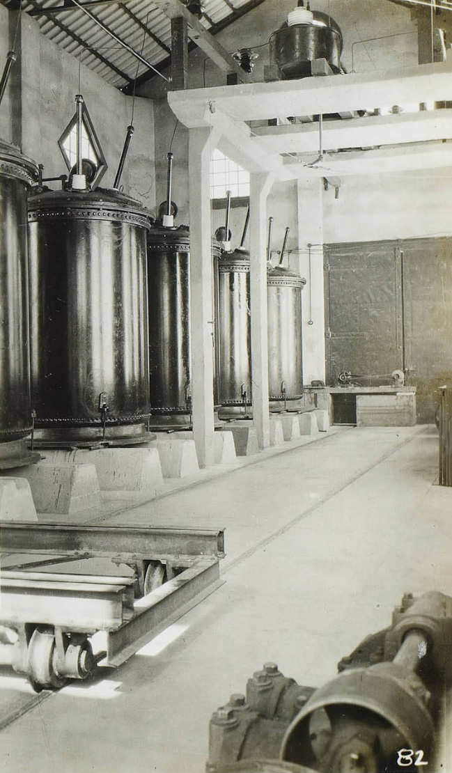
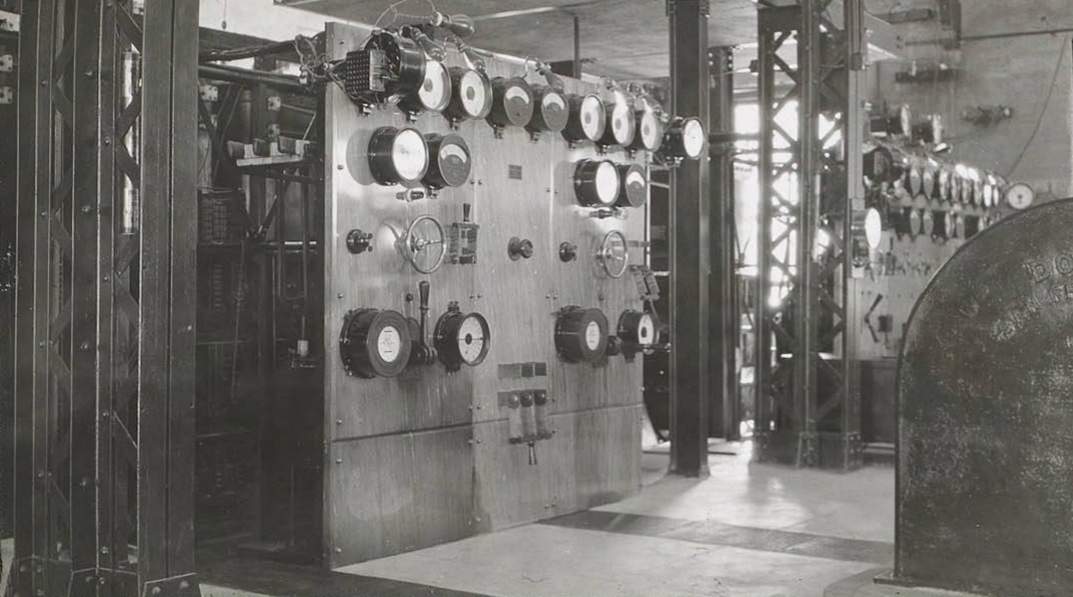
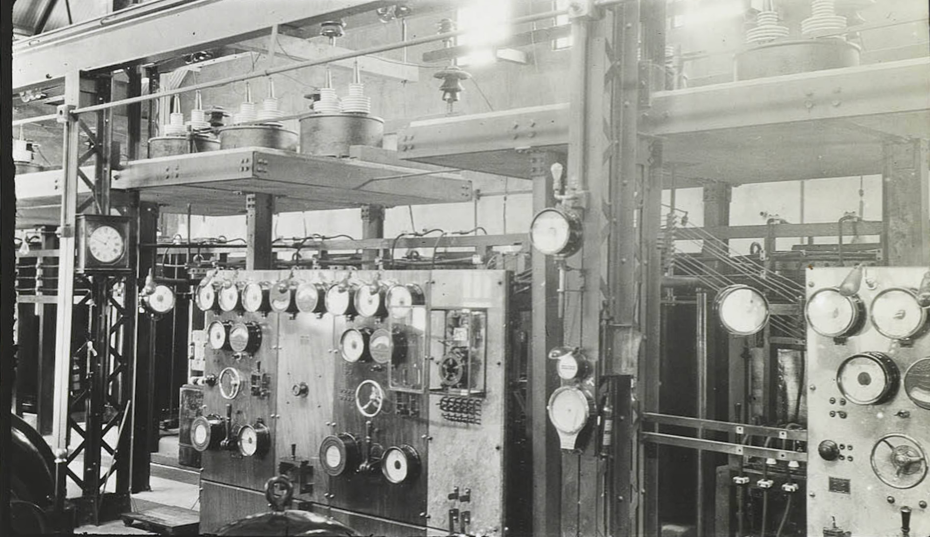
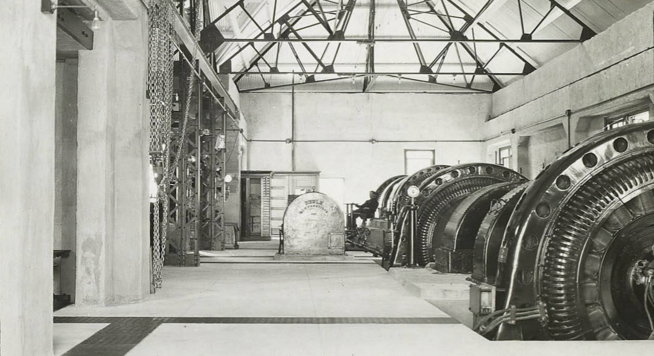
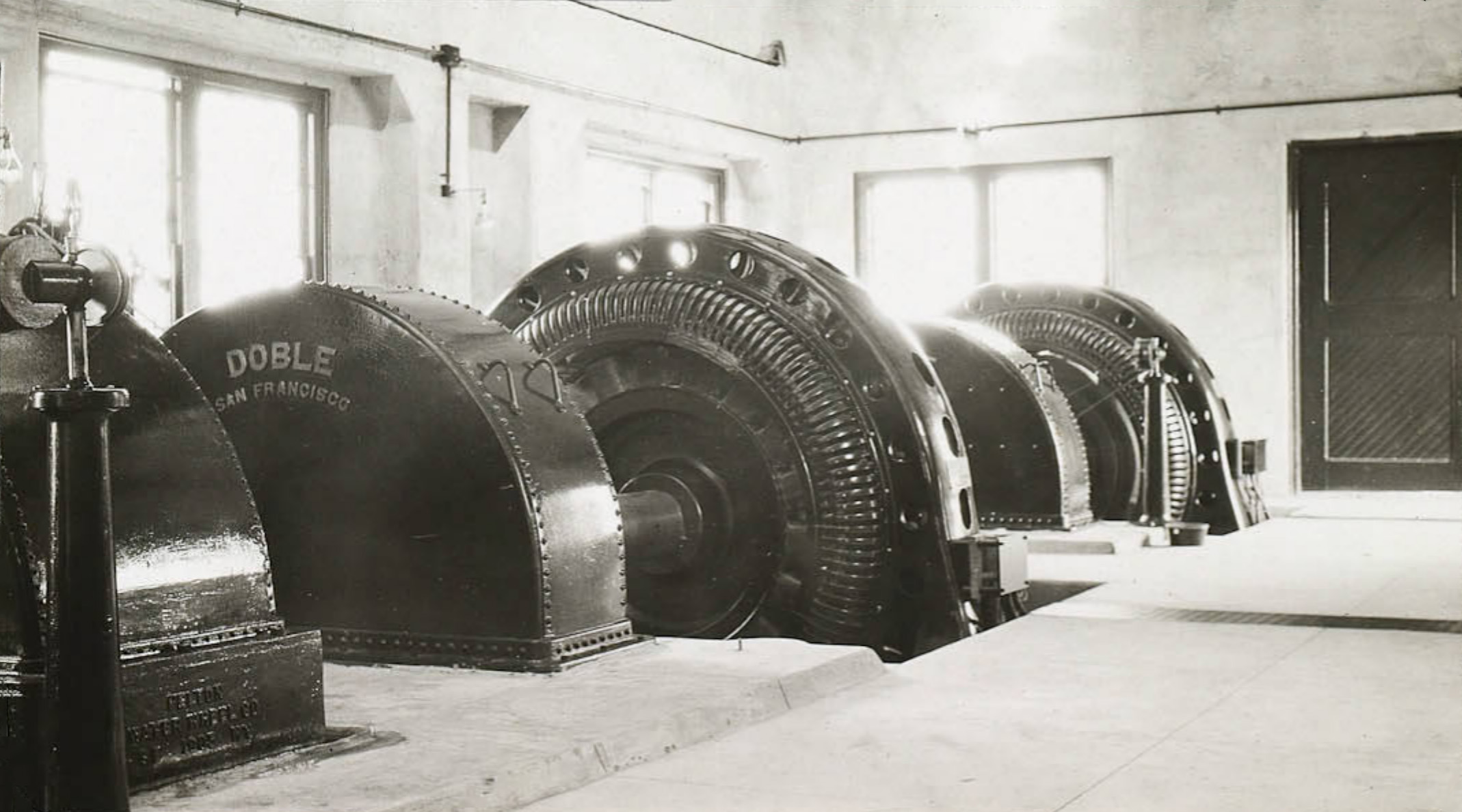
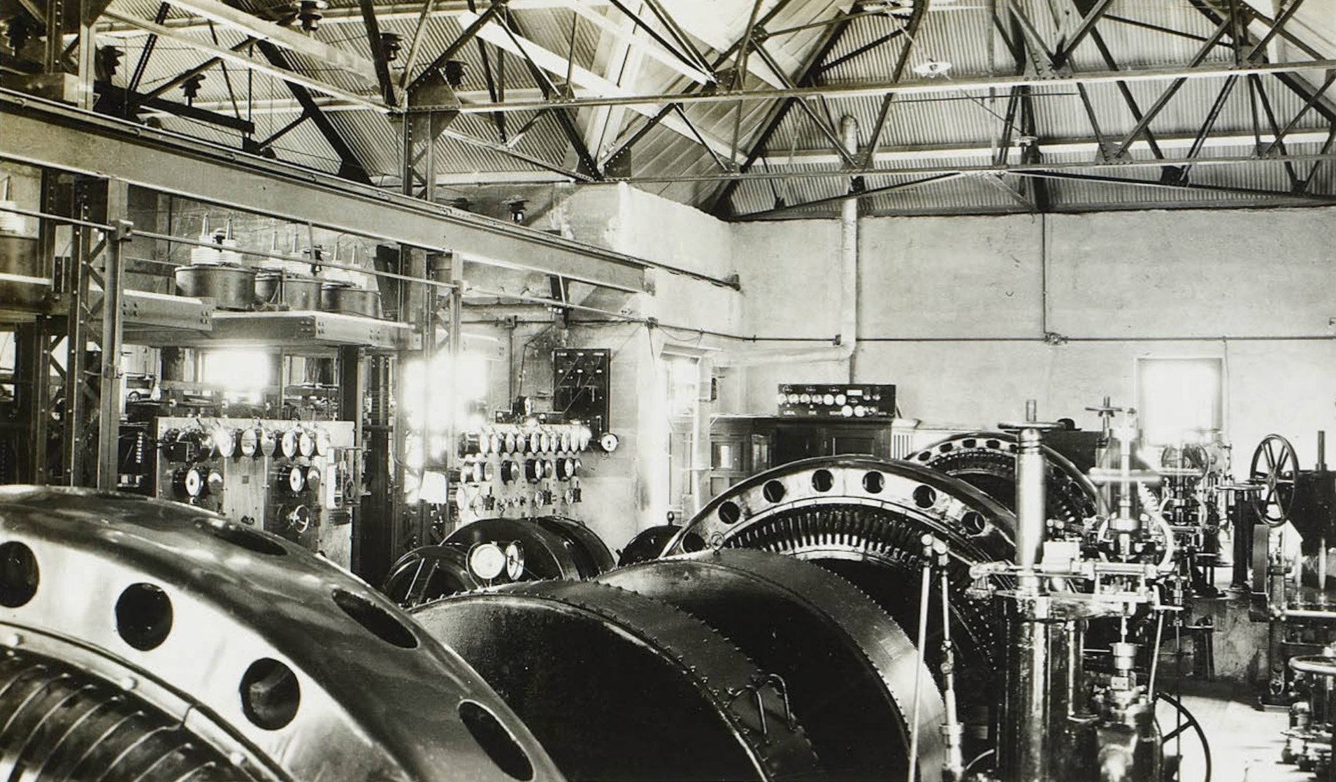
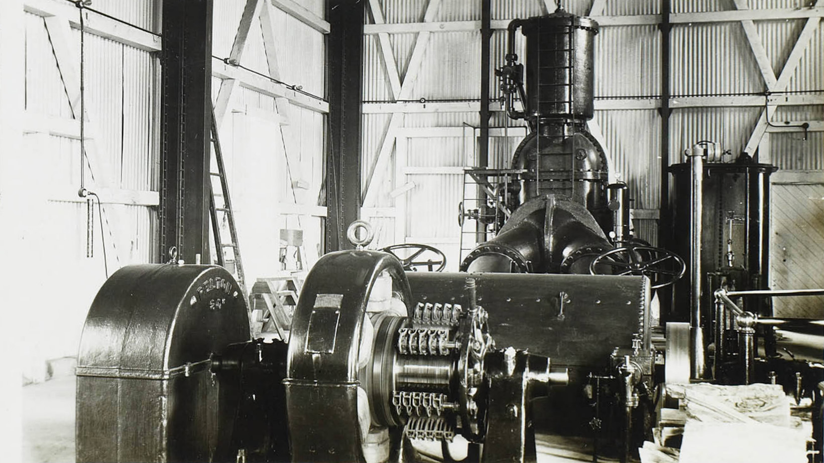
 Interior of the Rush Creek Power Plant - circa 1908 |
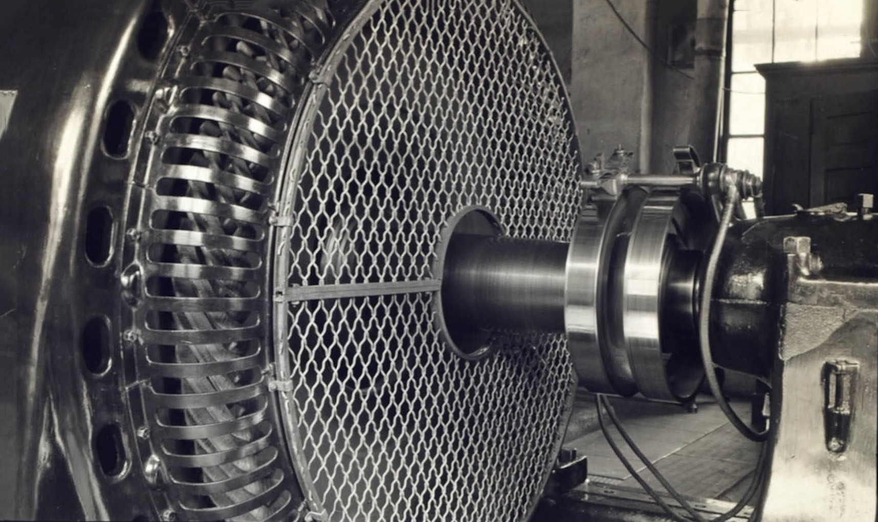
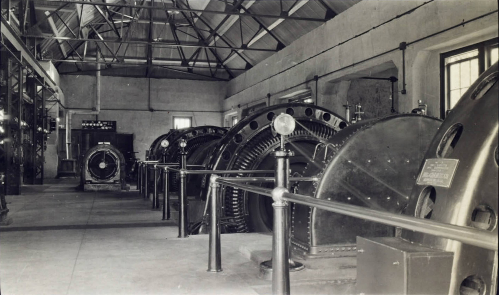
 Rush Creek Power Plant |
 Rush Creek Power Plant |
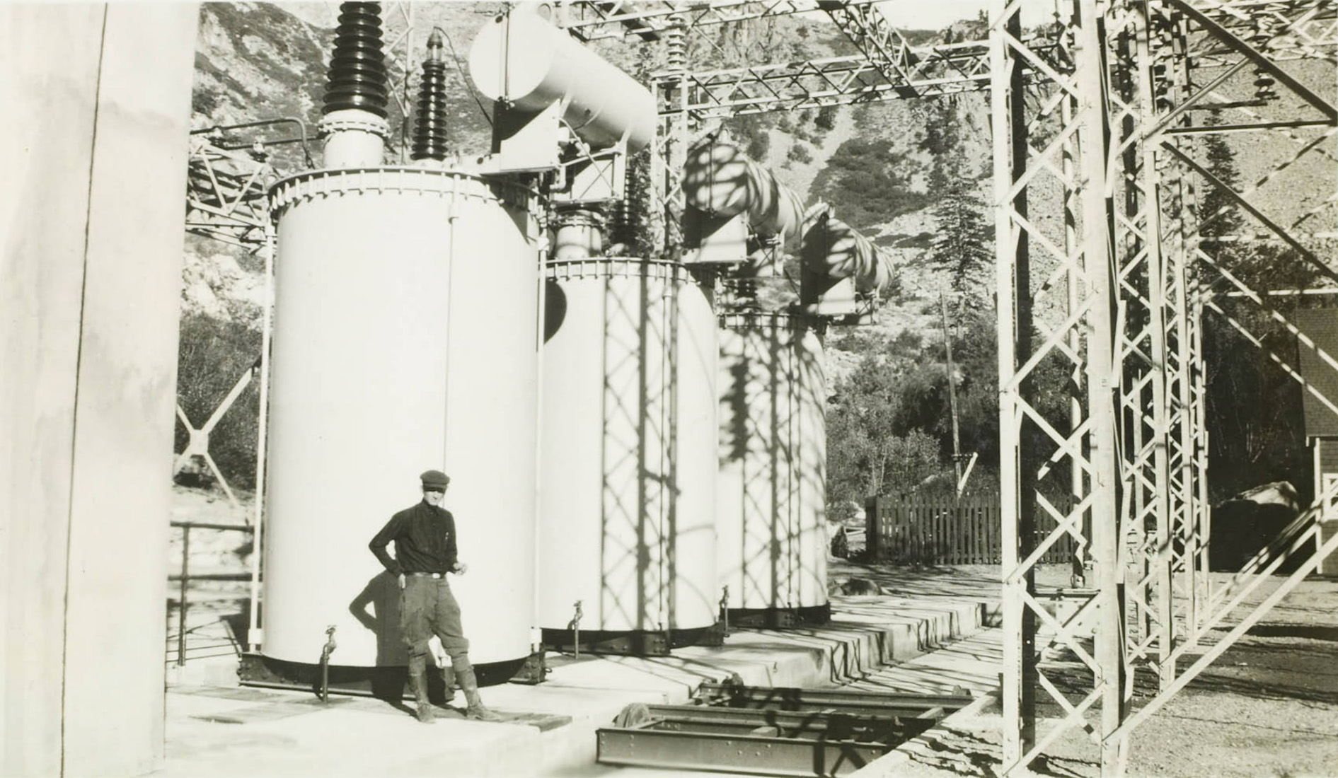
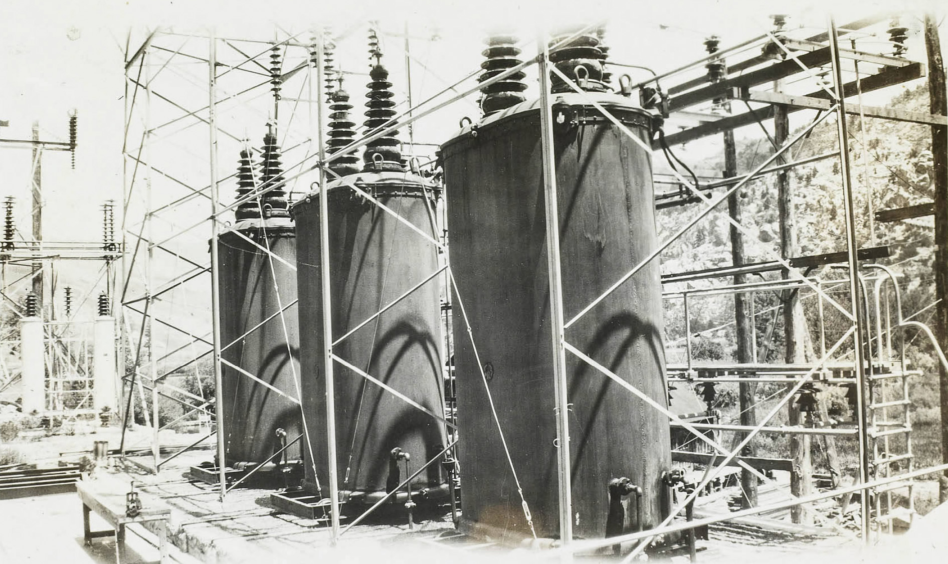 Silver Lake transformers |
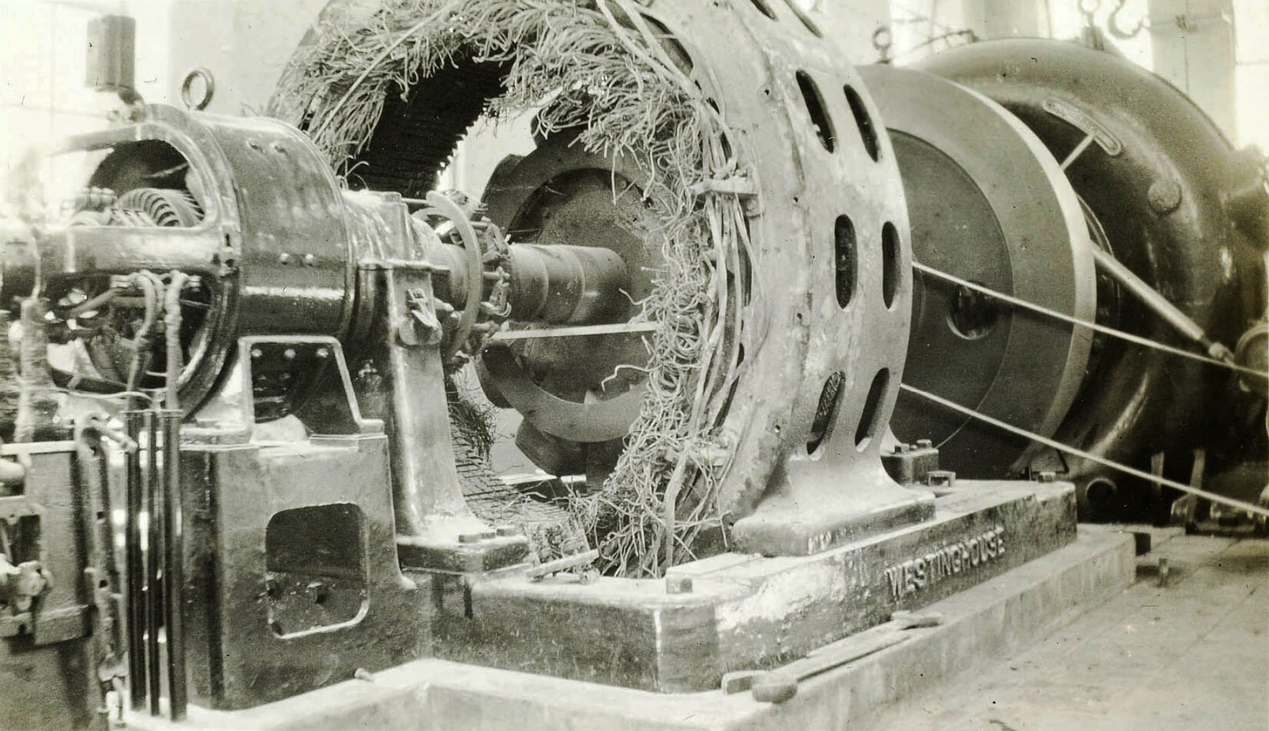 Generator after burn-up |
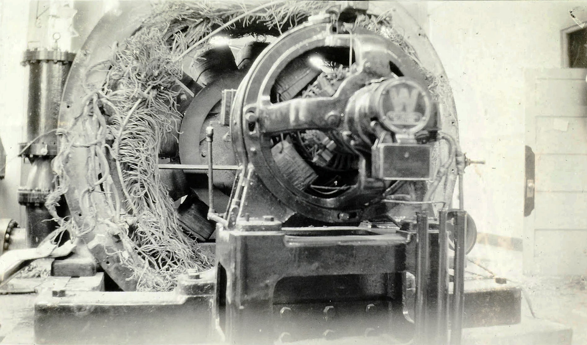 Generator after burn-up |
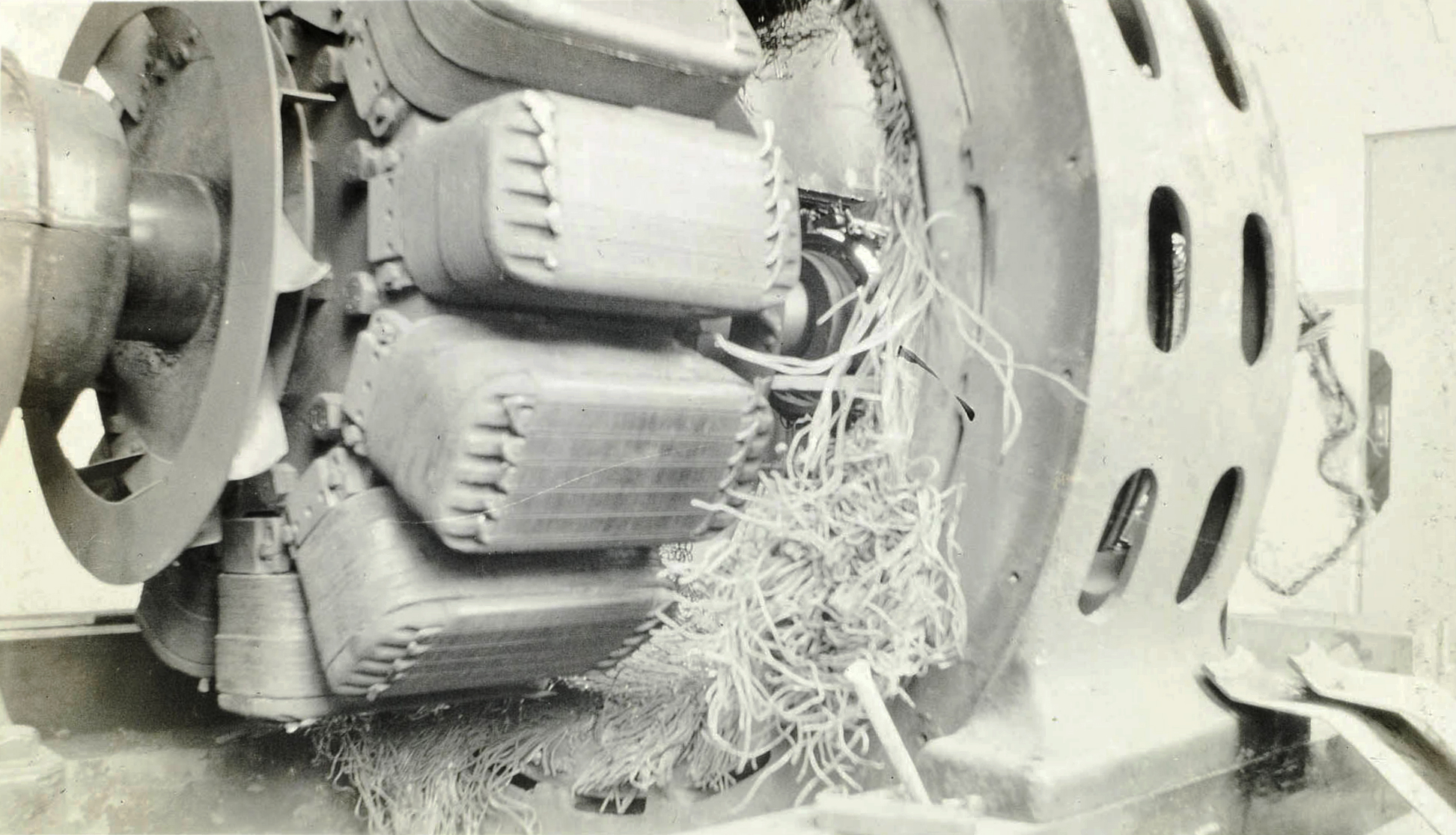 Generator after burn-up |
 Top to Bottom: Rush Meadows Lake, Gem Lake, Agnew Lake |
 Rush Creek Powerhouse complex near Silver Lake |
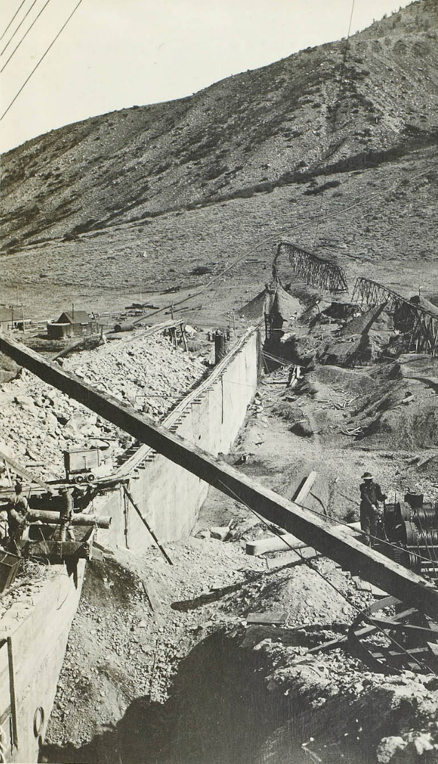
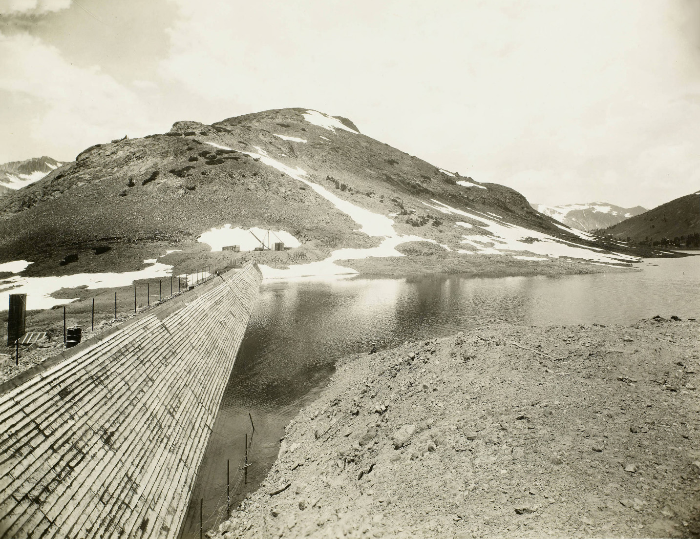
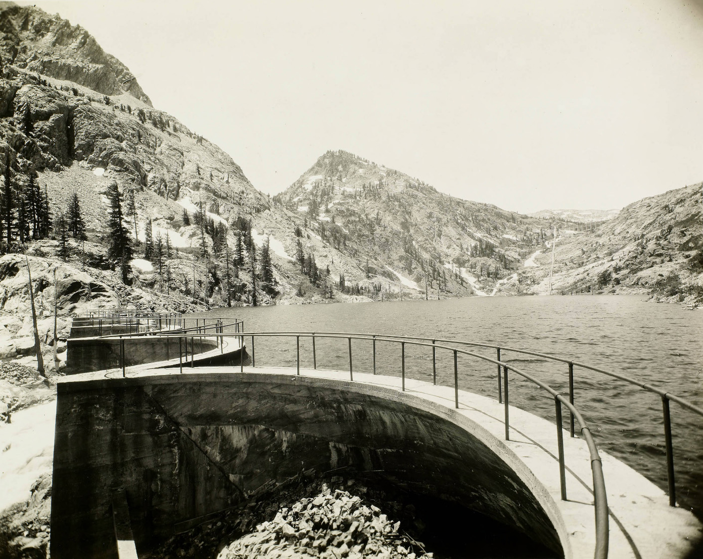
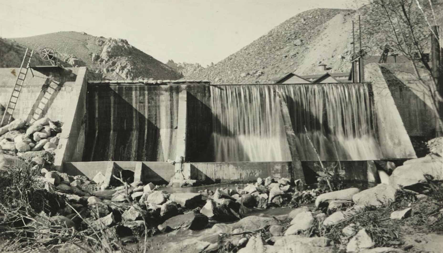
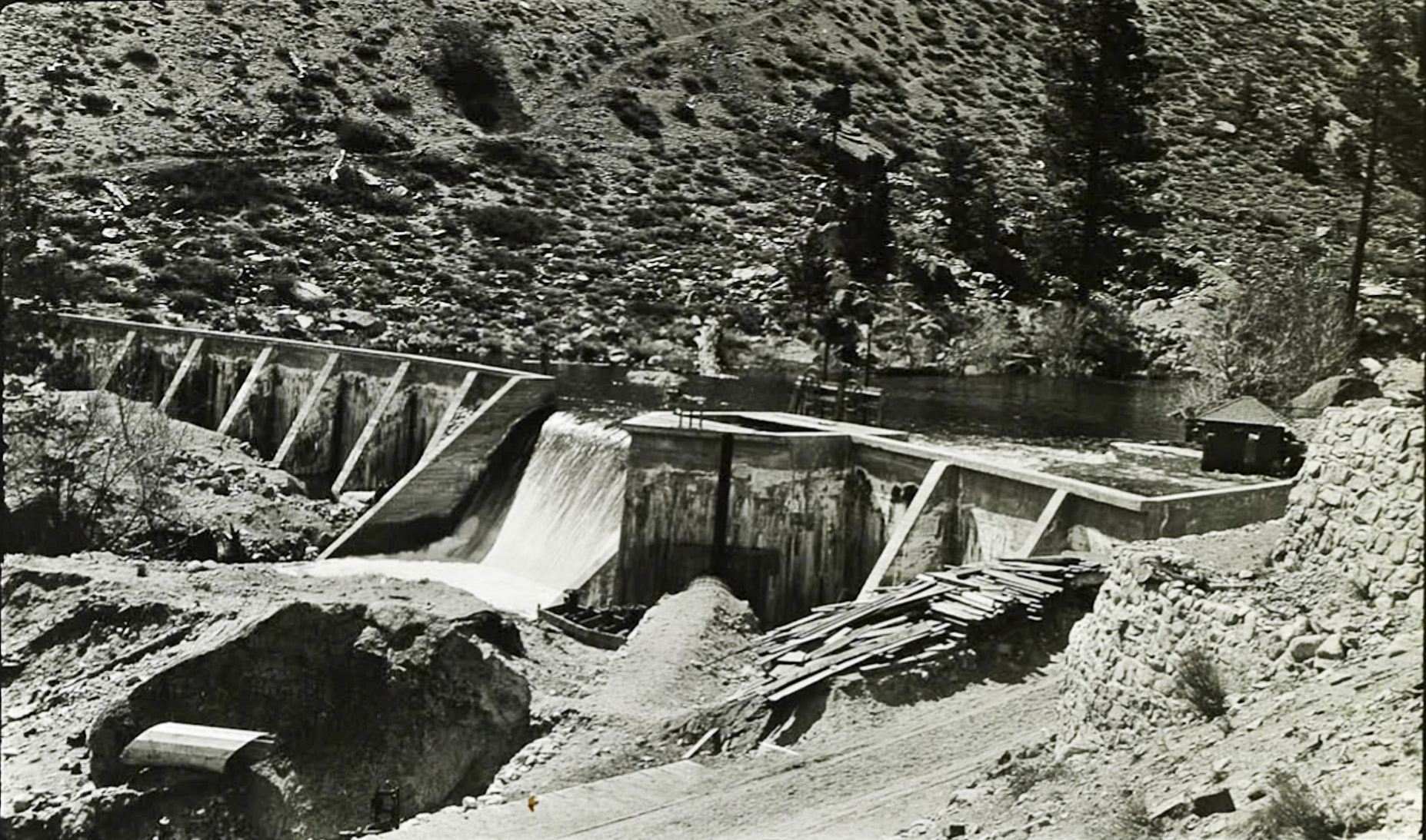
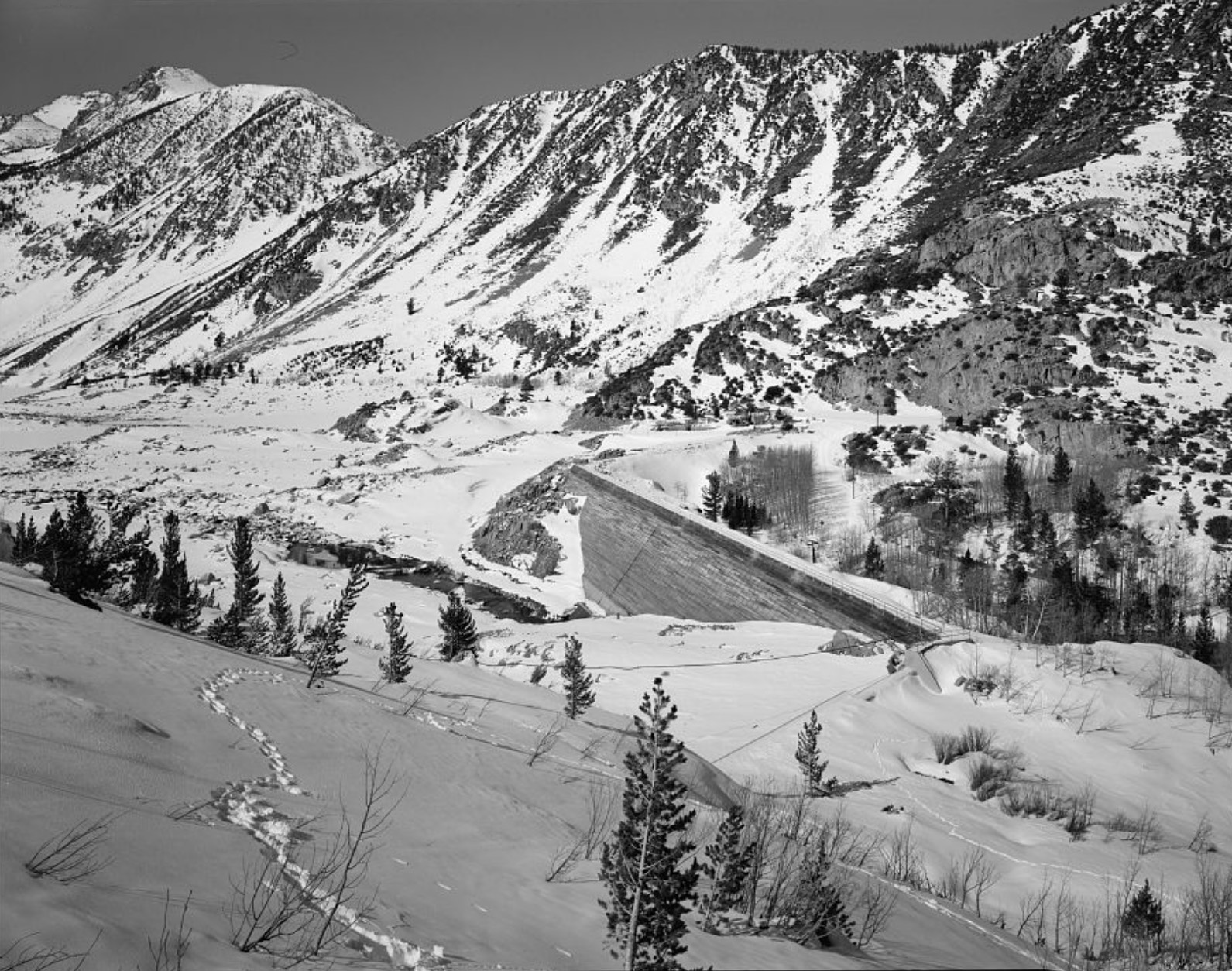
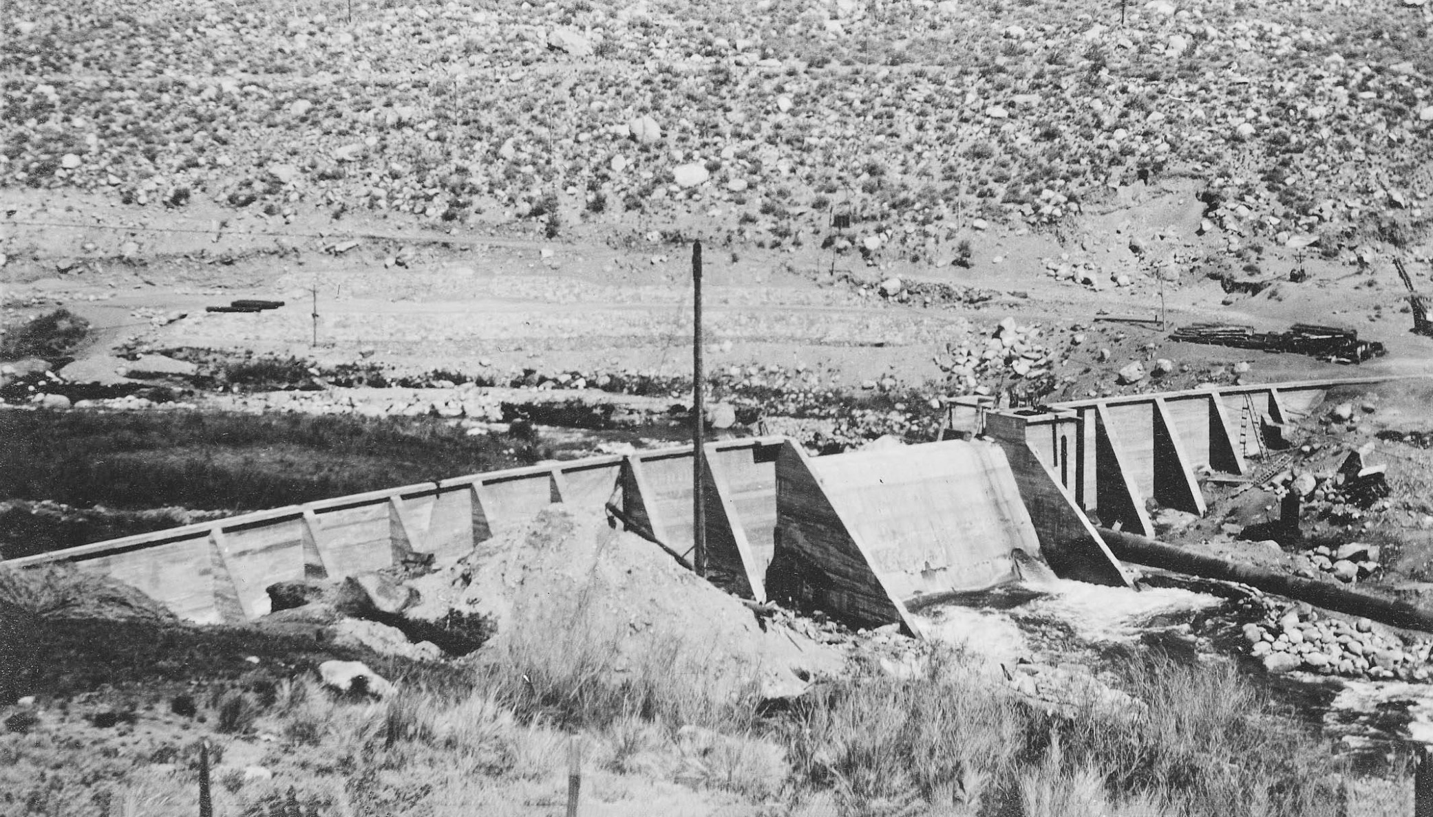
 Rush Meadows Dam - Rush Creek This is a single arch type reinforced concrete structure with a straight overflow gravity section and reinforced concrete abutment at junction of arch and spillway. The dam was completed in 1925. |
 Gem Lake Dam |
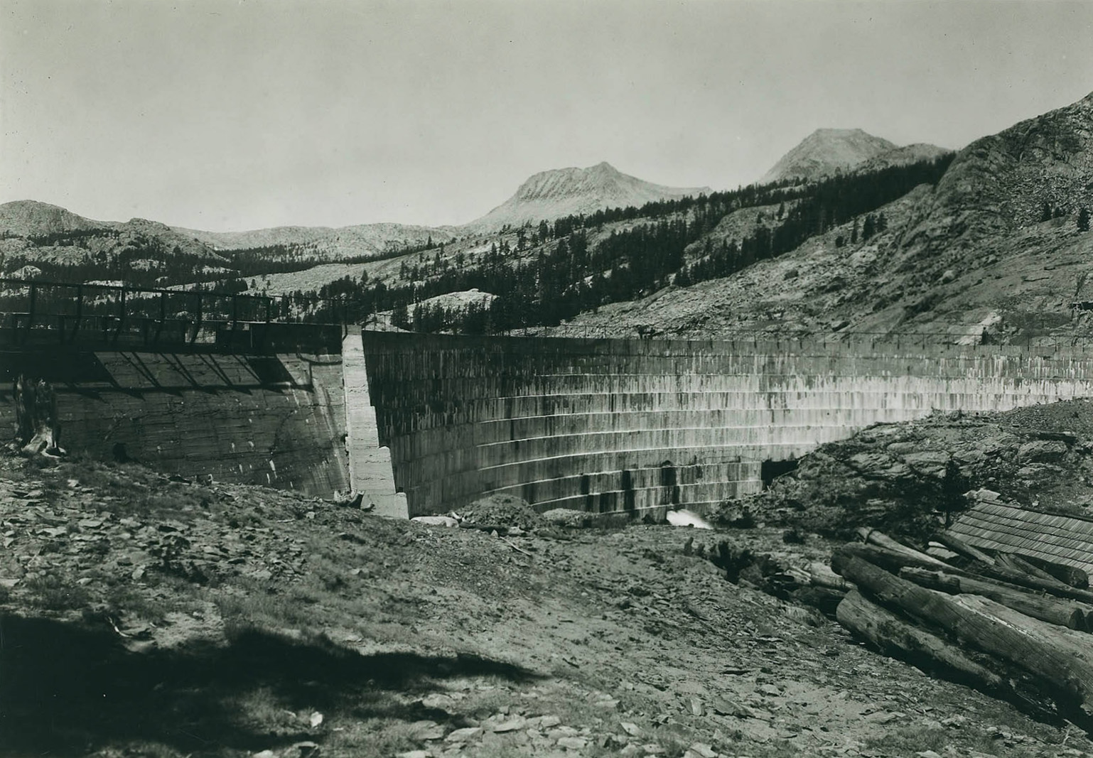 Rush Meadows Dam - Rush Creek |
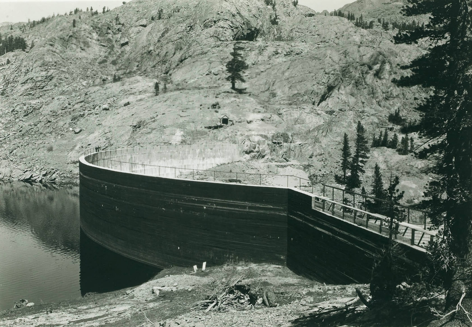 Rush Meadows Dam - Rush Creek |
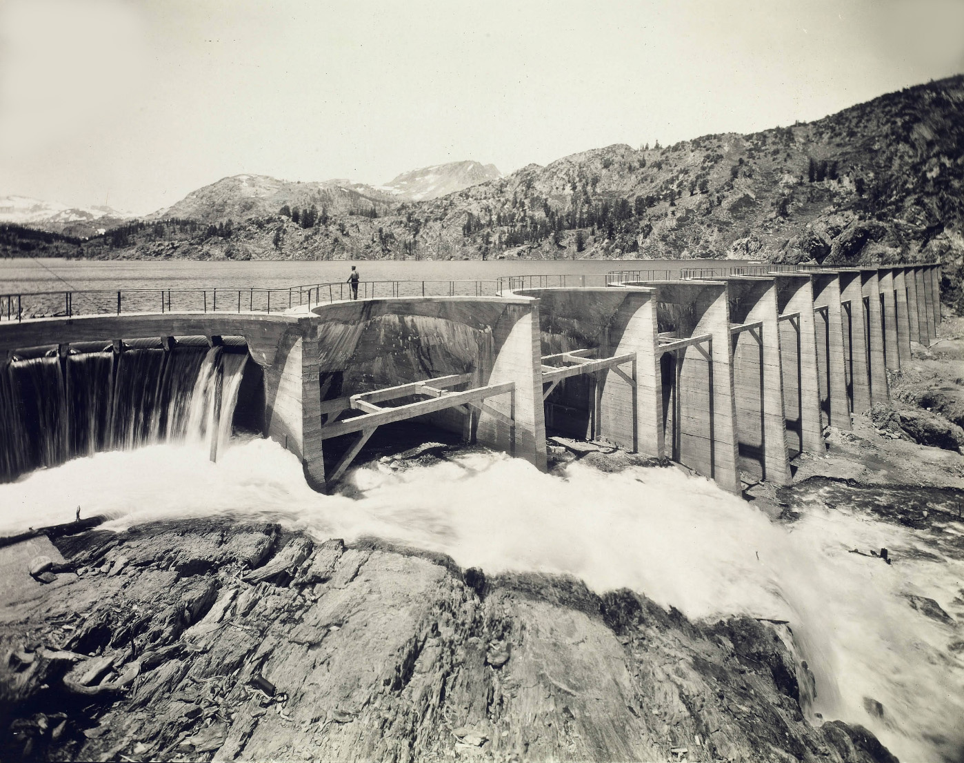
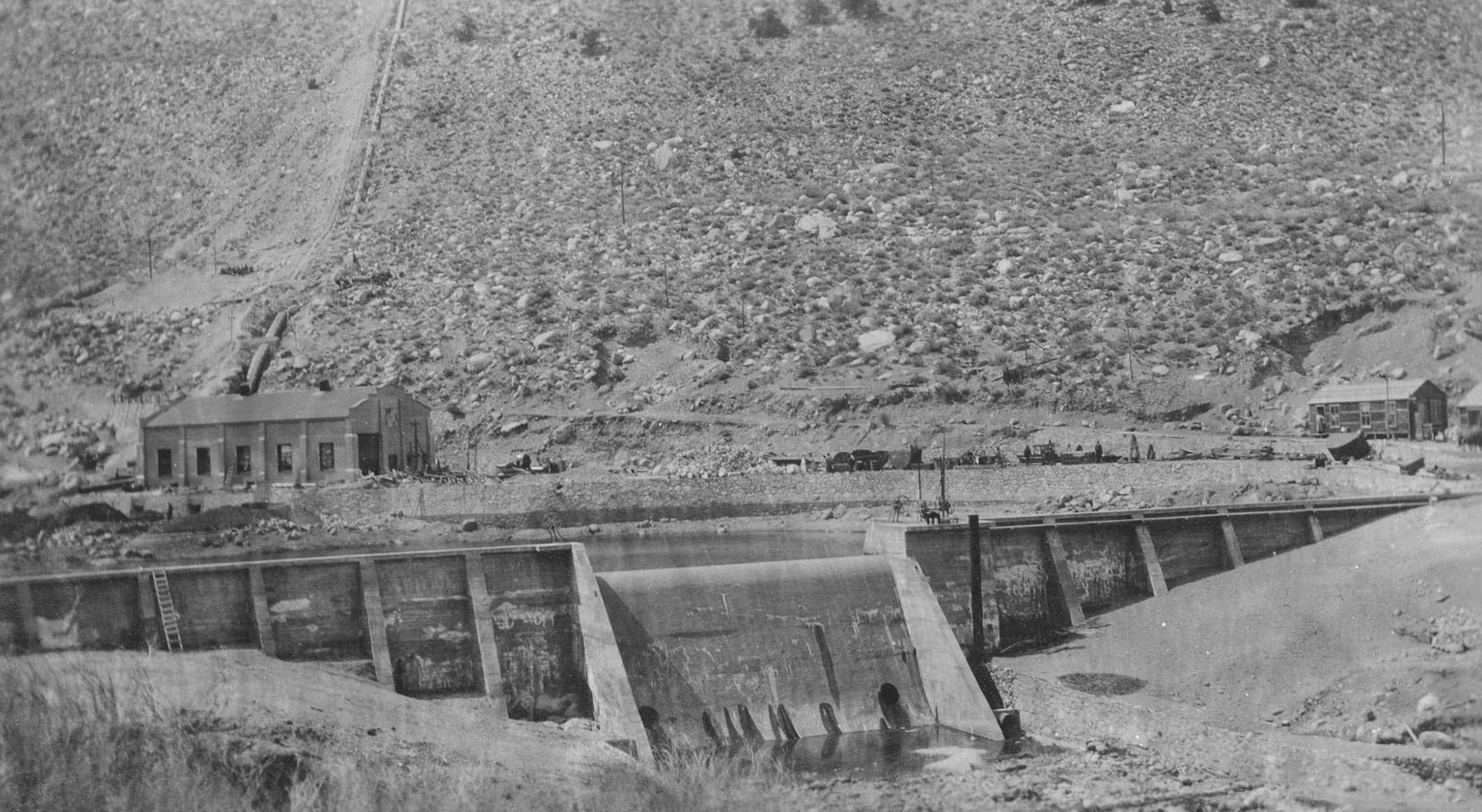
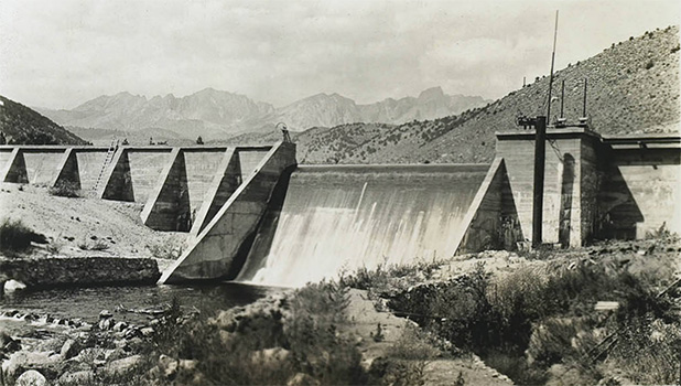
 Agnew Dam and Reservoir - July 1927 The dam consists of 4 arches of 40' span each and 2 of smaller span supported by heavy concrete abutments. This dam has a production value of 697,000 kilowatt-hours when released and used through the Rush Creek Power Plant. Tram 2 to Gem Lake and the Gem Dam can be seen in the upper right. |
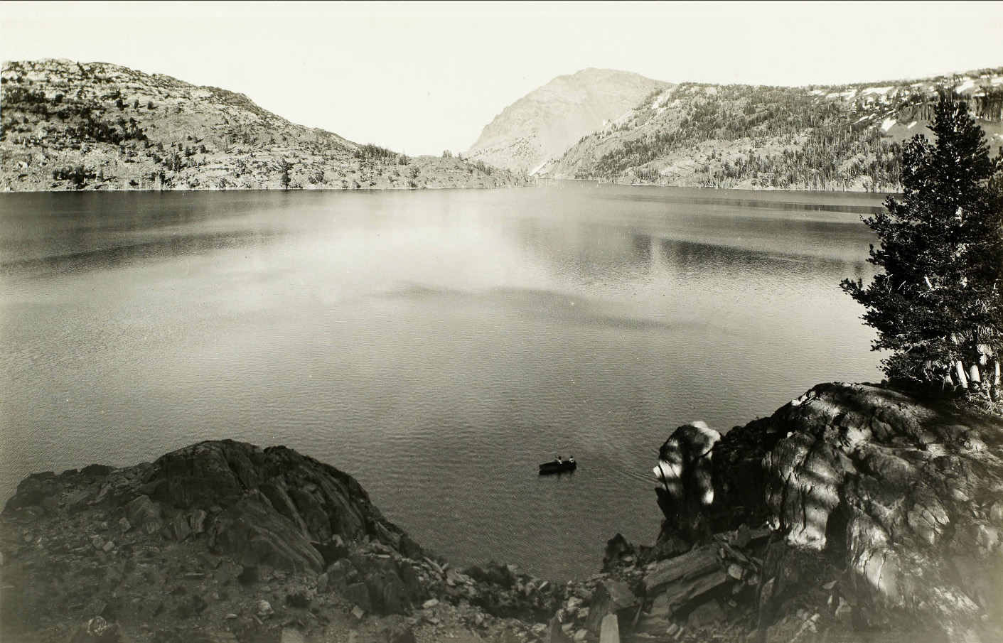 Gem Lake Reservoir - Rush Creek This is the main storage reservoir for the Rush Creek Power Plant. It has a storage capacity of 18,424 acre feet and a production value of 18,424,000 kilowatt-hours. |
 Gem Lake Dam Water spilled from this dam is impounded by Agnew Dam. |
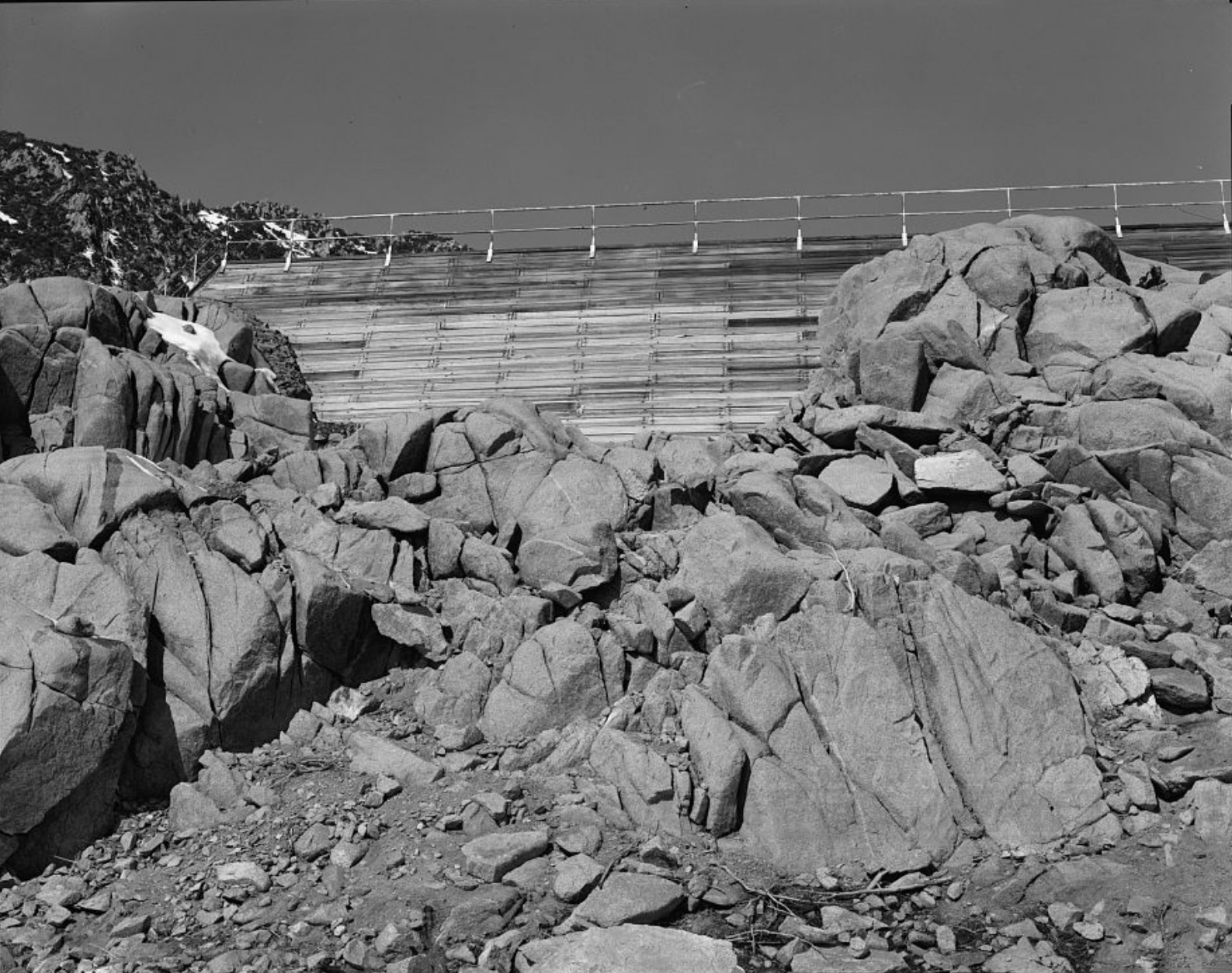
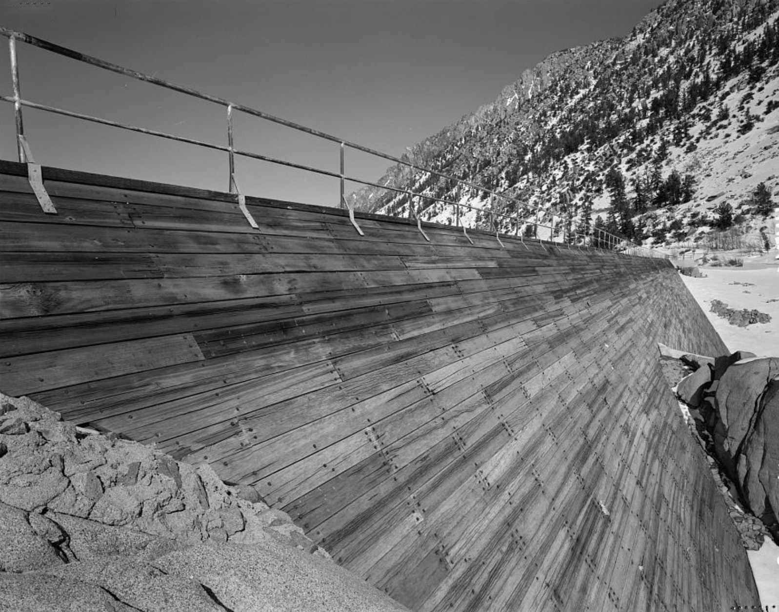
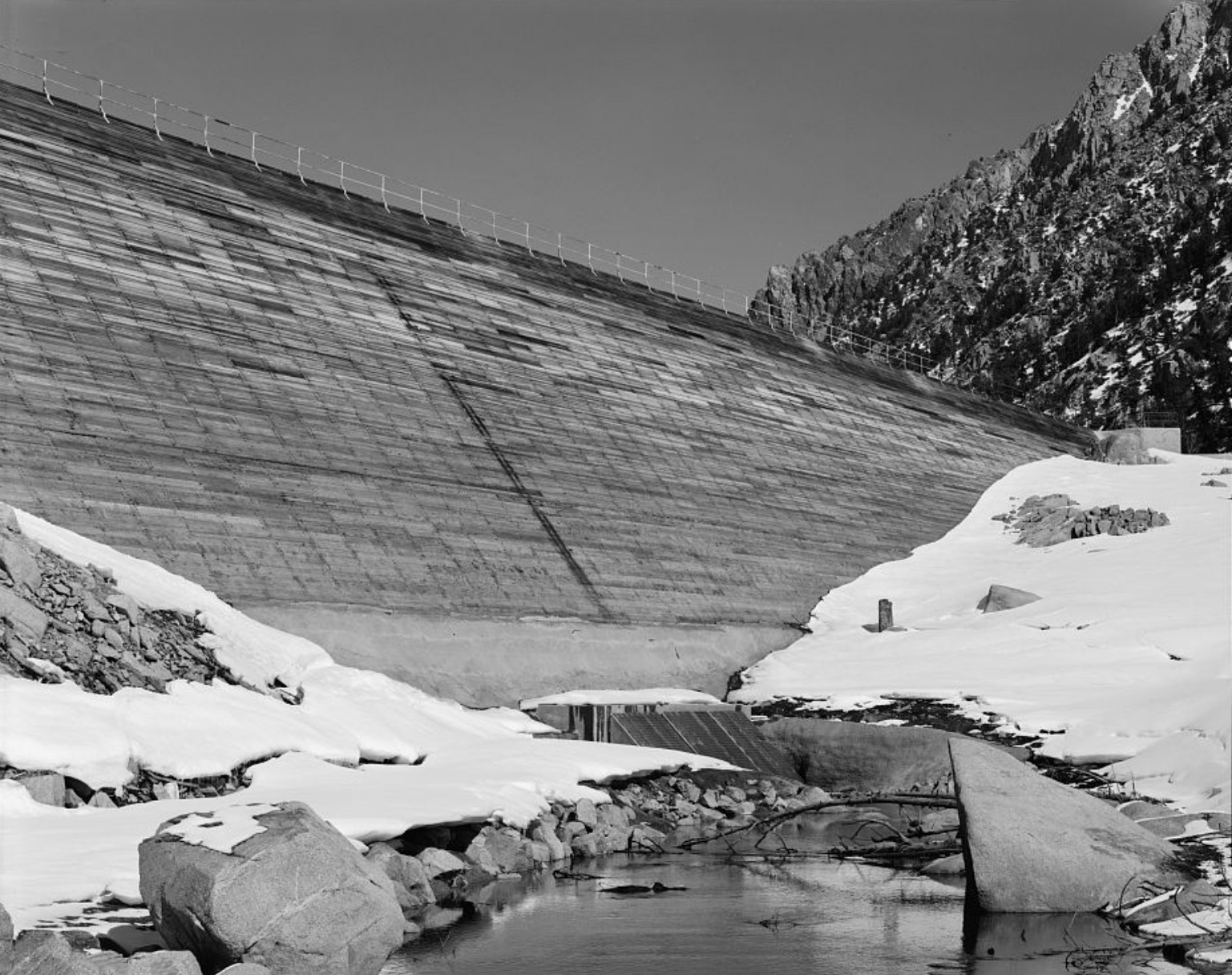
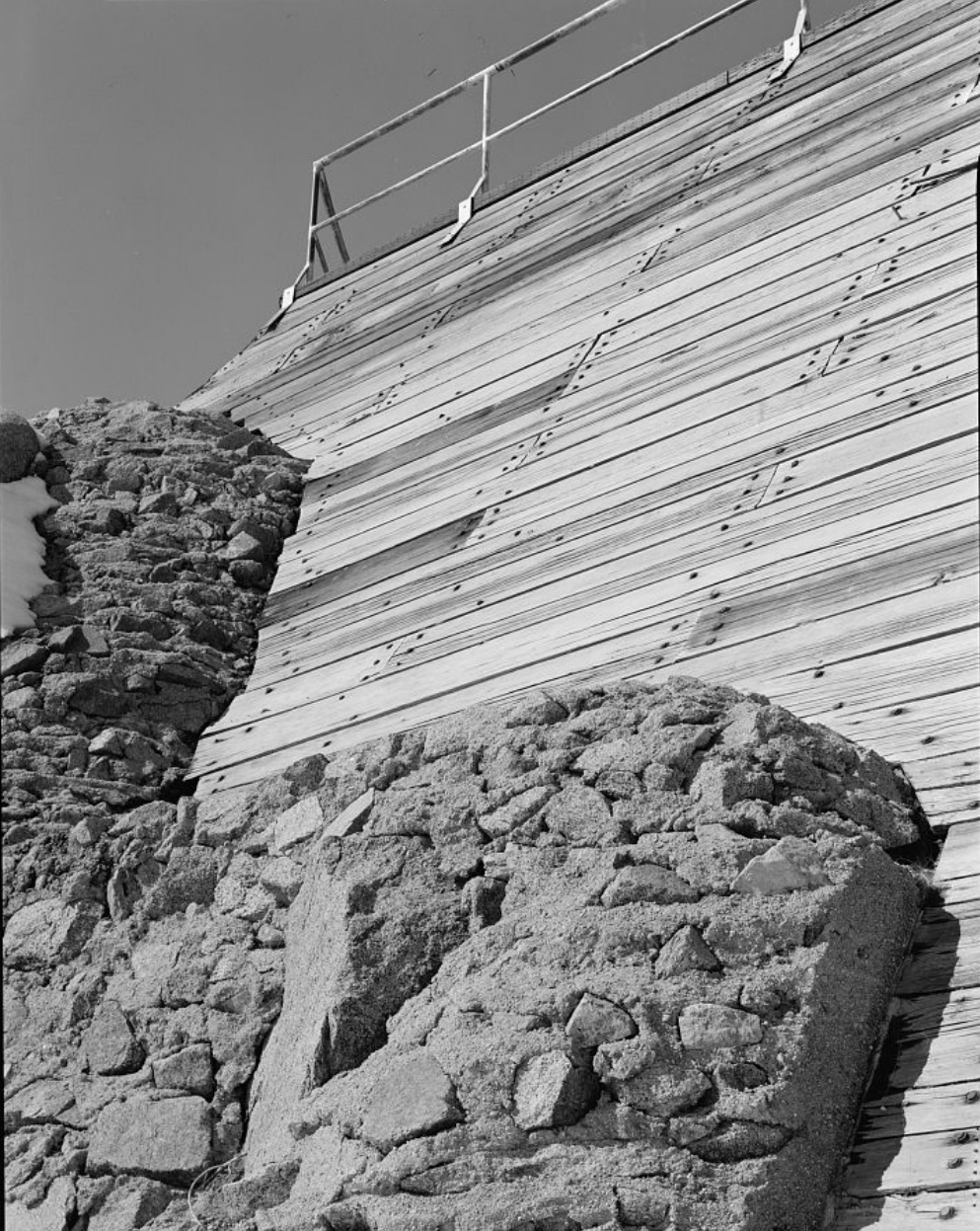
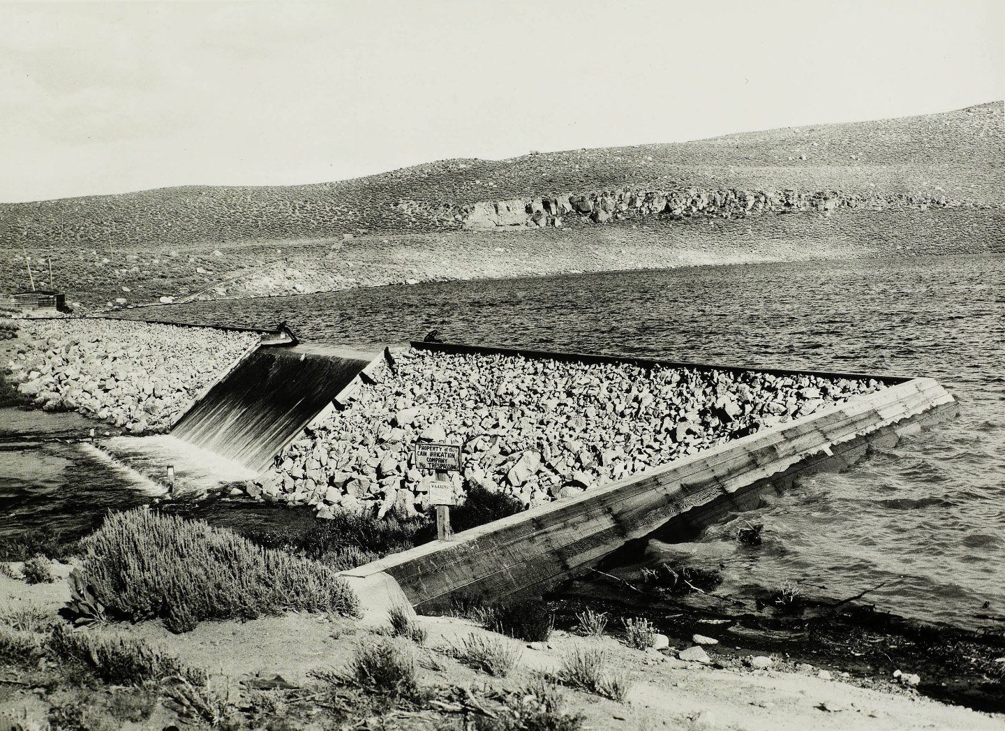 Grant Lake Dam This is a timber-faced, rock-filled structure impounding water for use on the Cain Ranch |
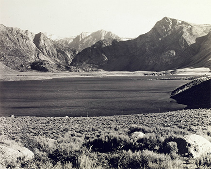 Grant Lake Reservoir Situated below the Rush Creek Hydro-Electric Plant, this reservoir has a present capacity of 10,111 acre feet. The water impounded here is used for irrigation of the Cain Ranch. |
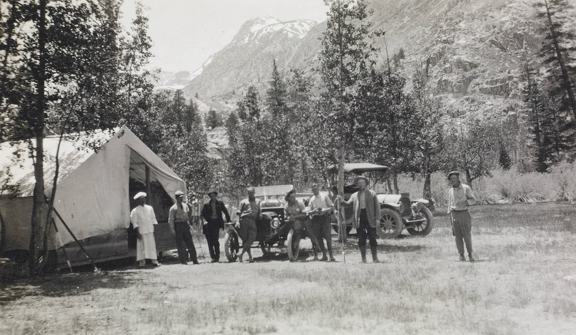
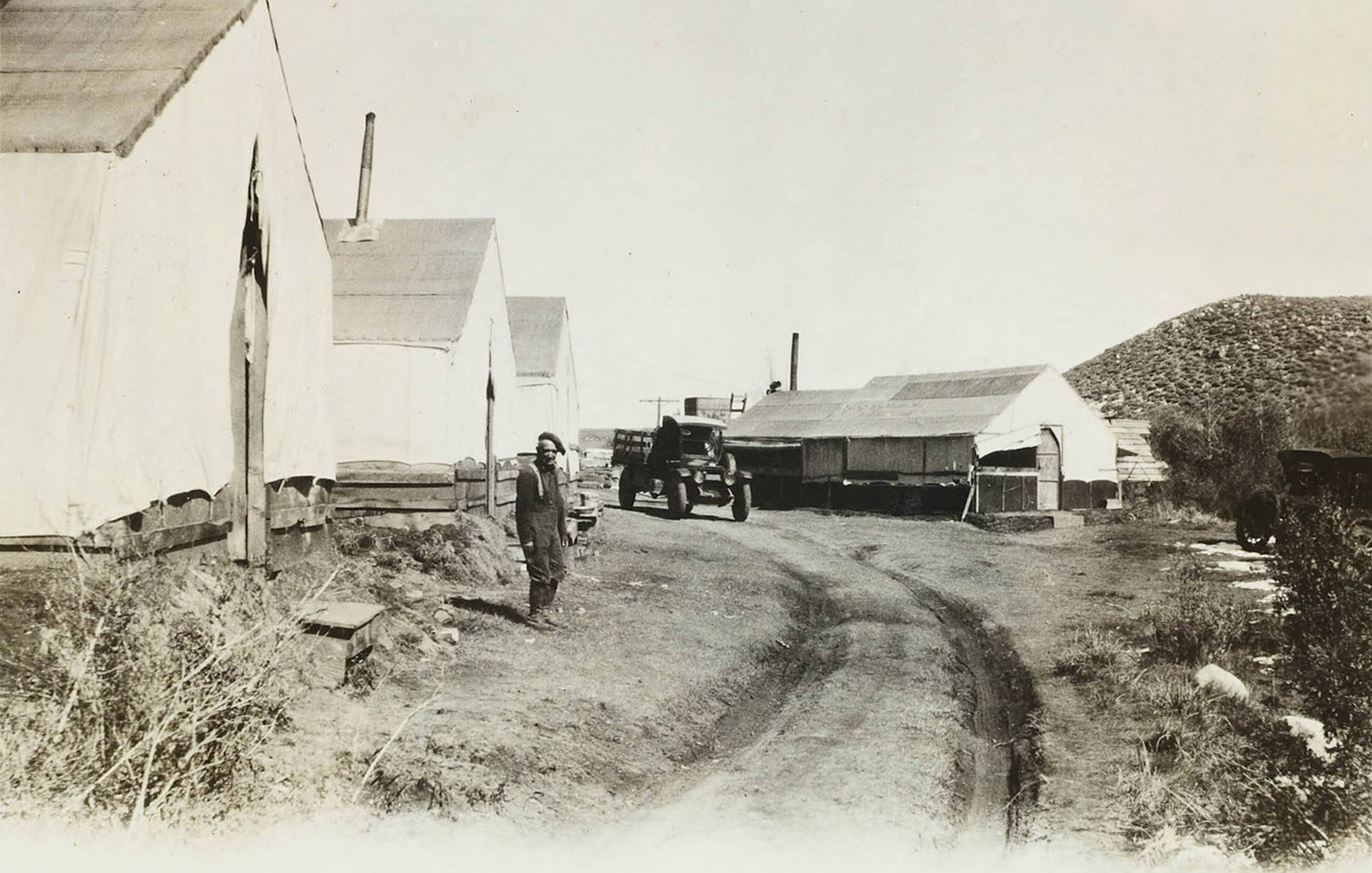 Grant Lake Camp |
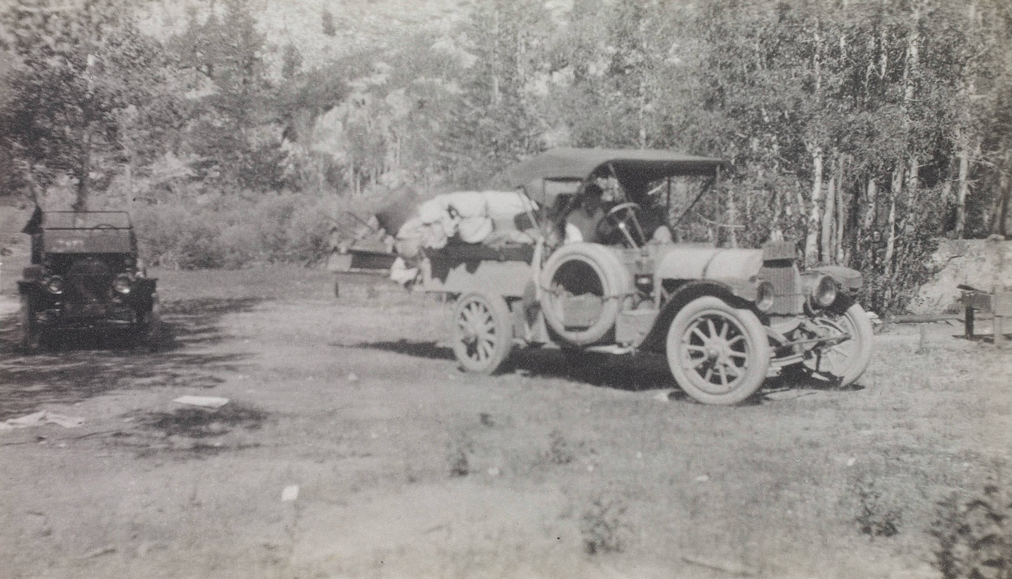
 Company cars at Grant Lake Camp |
 Grant Lake Camp |
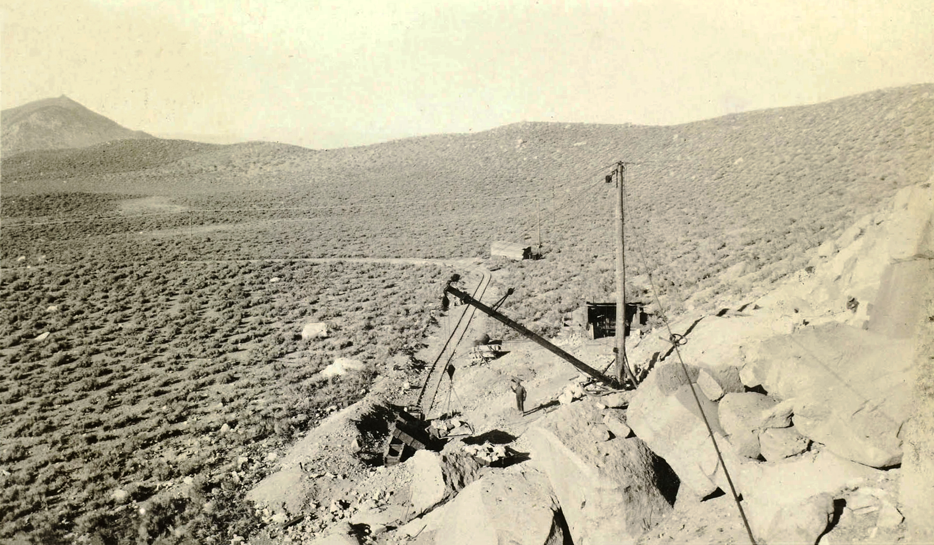
 Grant Lake Dam construction |
 Grant Lake Dam construction |
 Grant Lake Dam construction |
 Grant Lake Dam construction |
 Transporting rock to the Grant Lake Dam |
 Loading rock to the Grant Lake Dam |
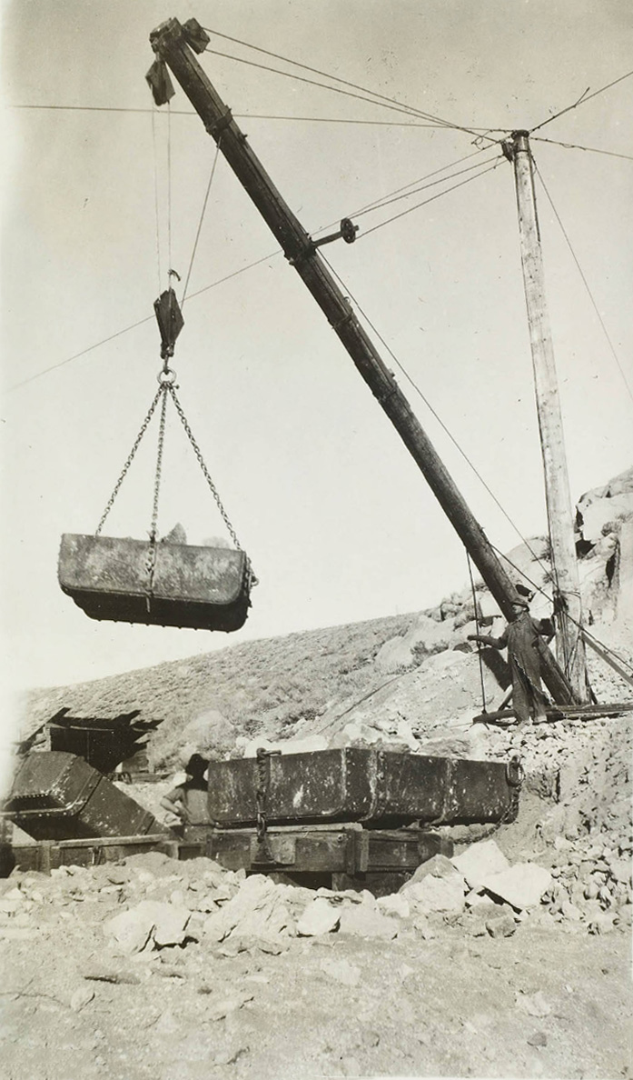 Using hoist to load rock for the Grant Lake Dam construction |
 Loading rock to the Grant Lake Dam |
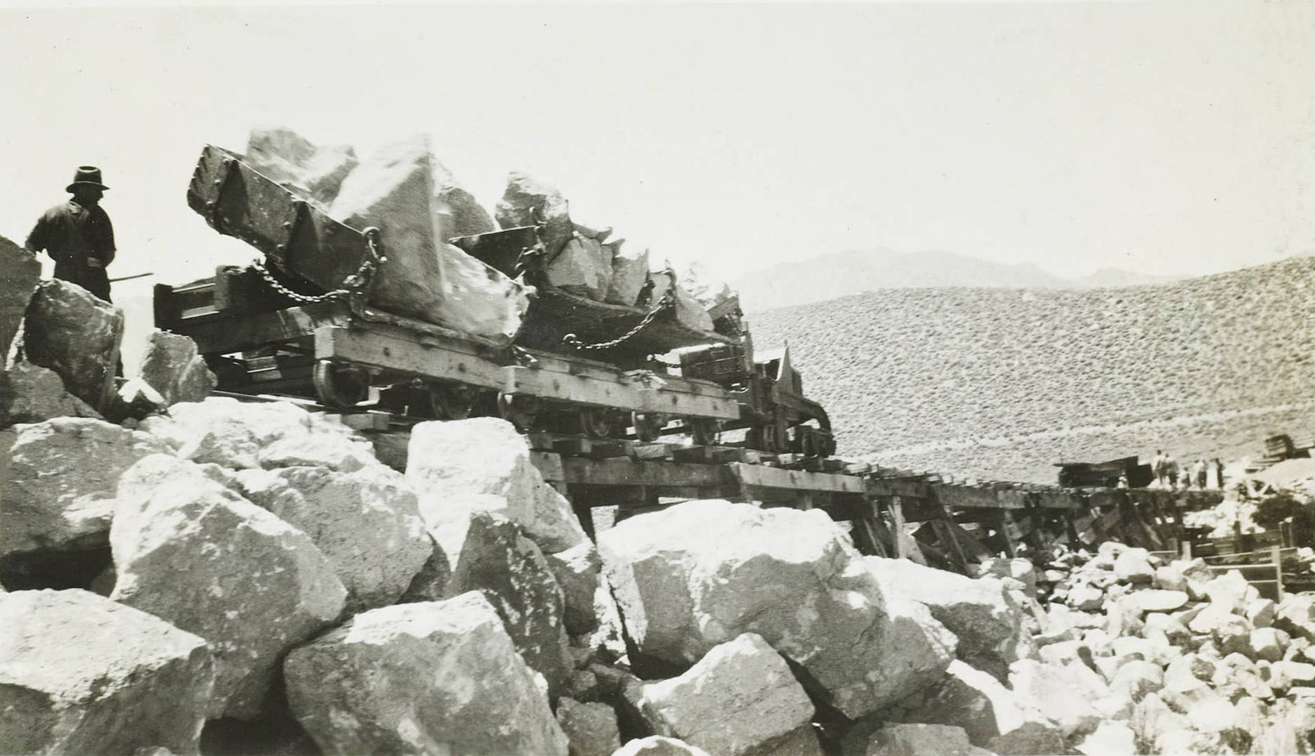 Unloading rock at the Grant Lake Dam |
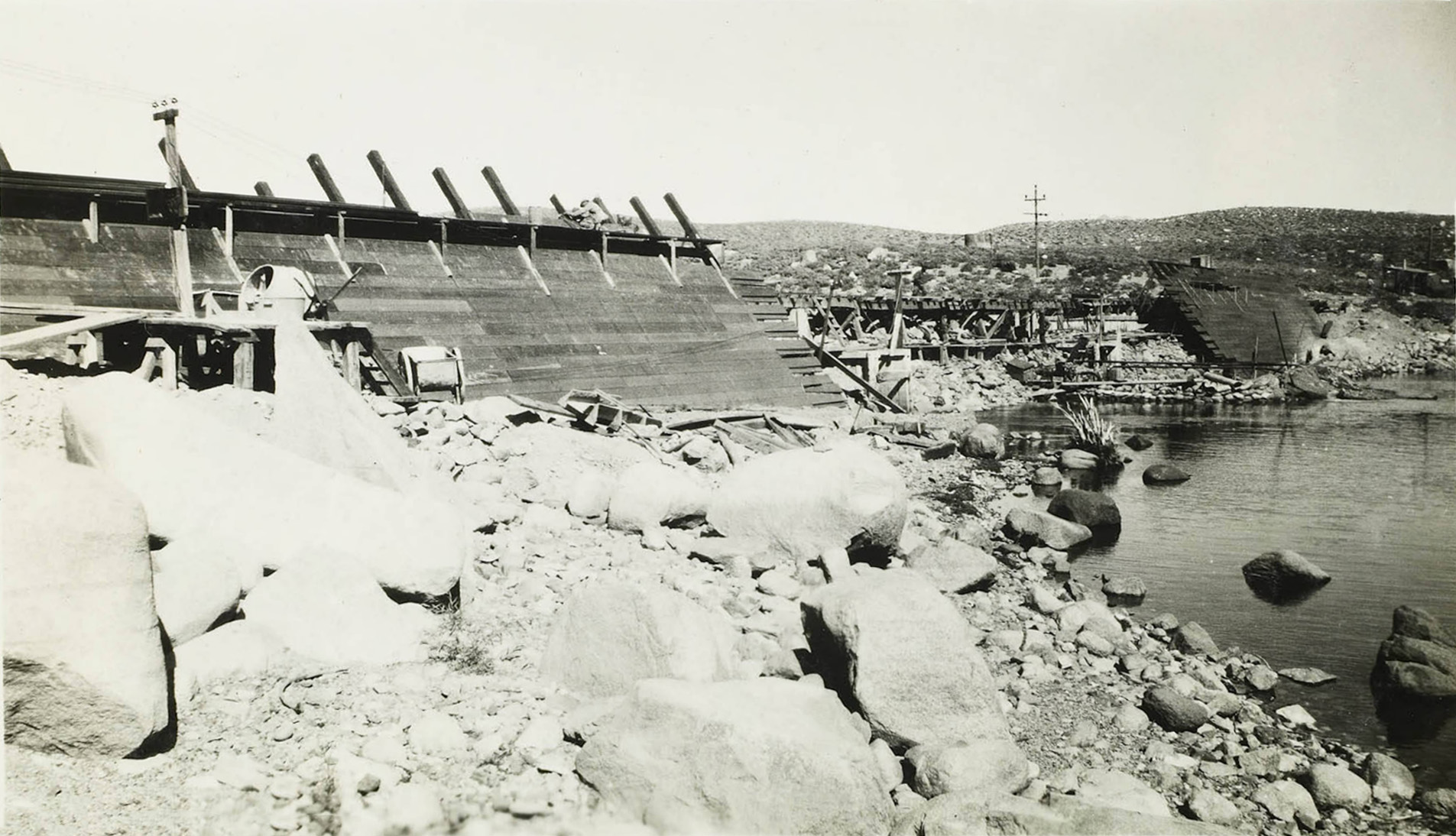 Grant Lake Dam under construction |
 Grant Lake Dam under construction |
|
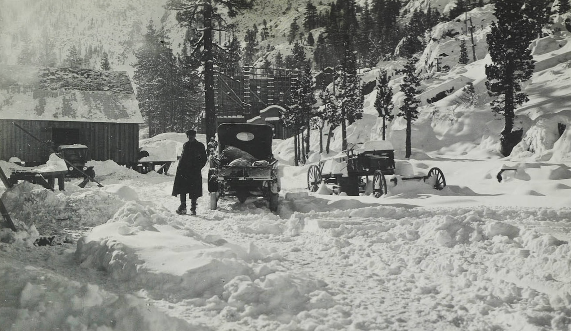
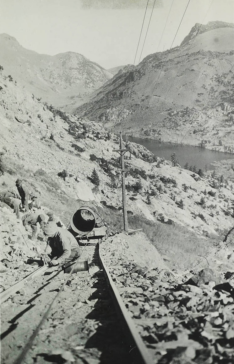
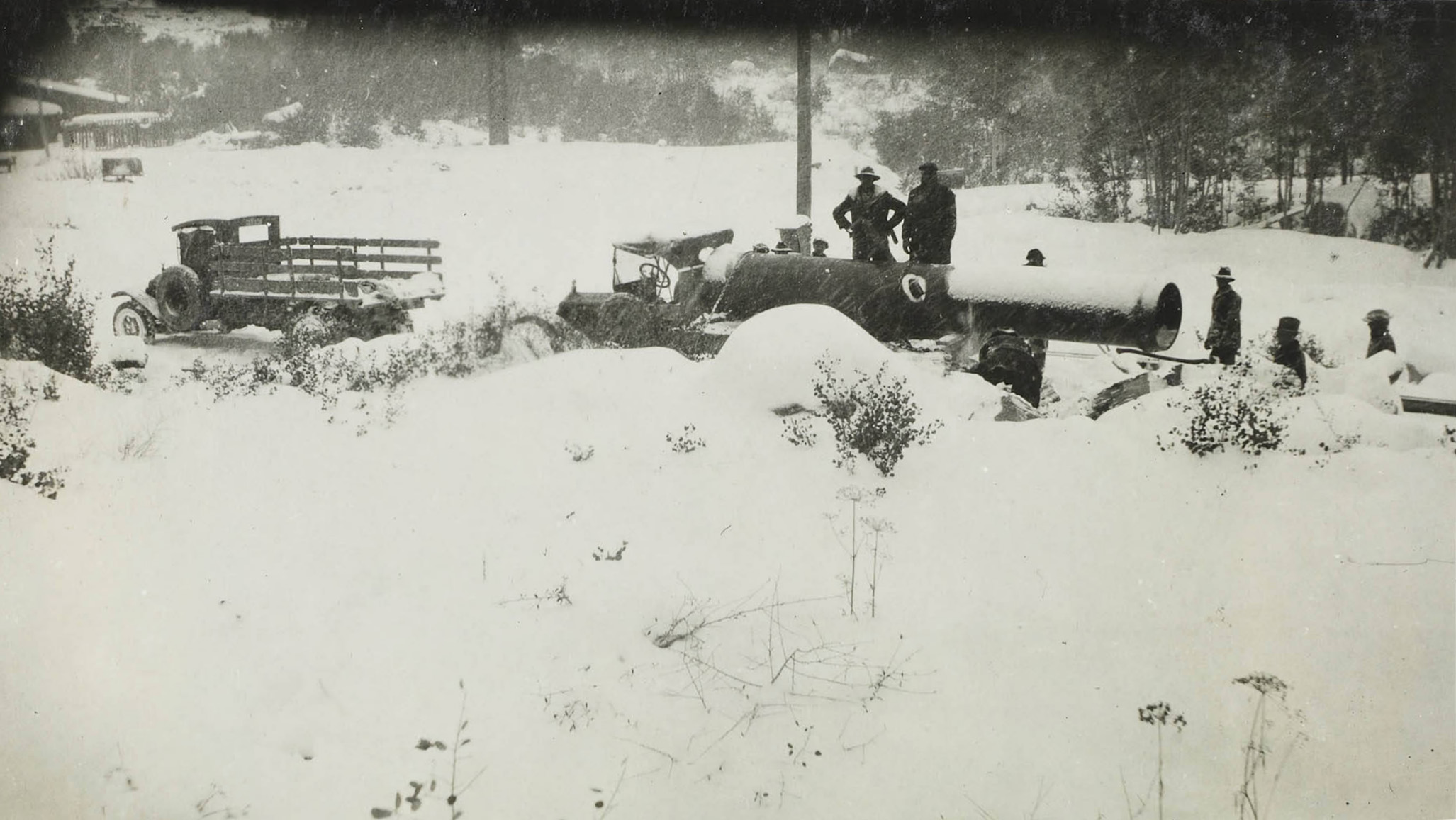 Hauling steel pipe to the Rush Creek Powerhouse in the winter |
|
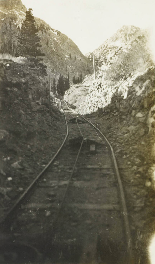
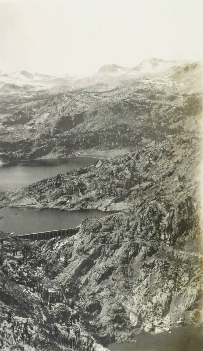
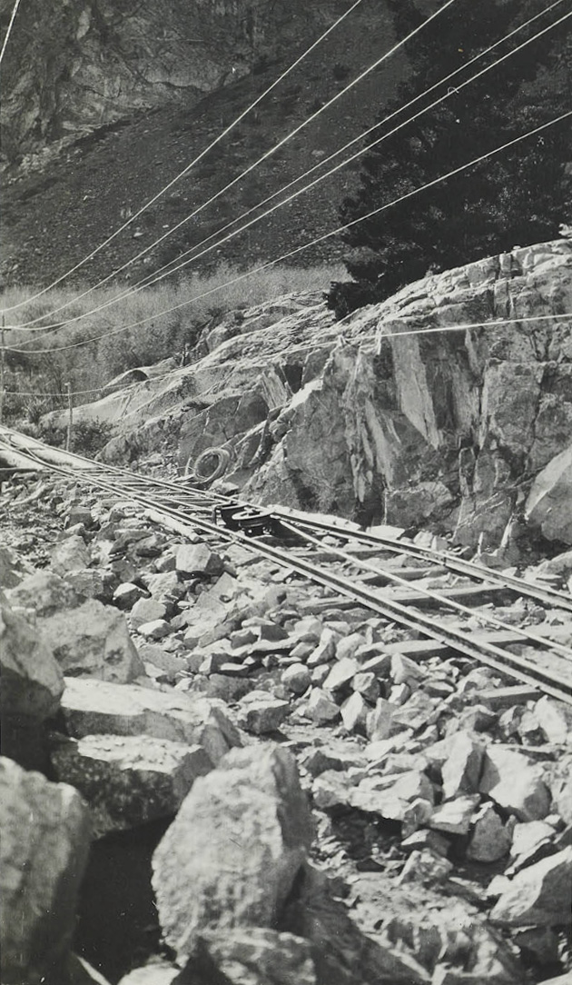
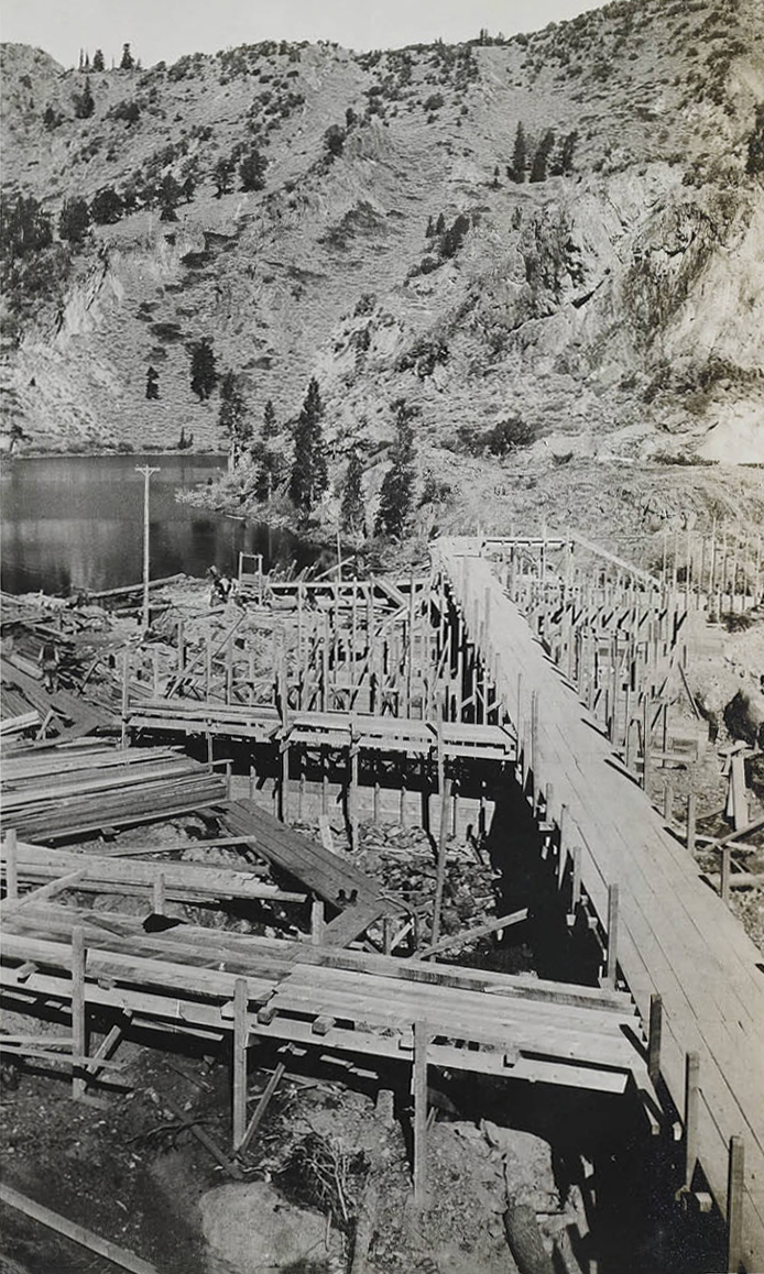
Silver Lake area to Agnew Lake (Tram 1) and Agnew Lake to Gem Lake (Tram 2) |
|
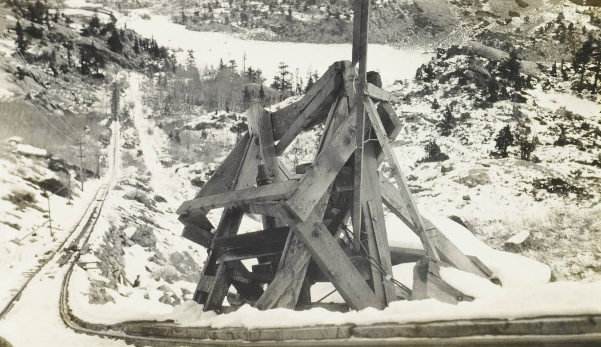
 Typical angle sheave on Tram 1 |
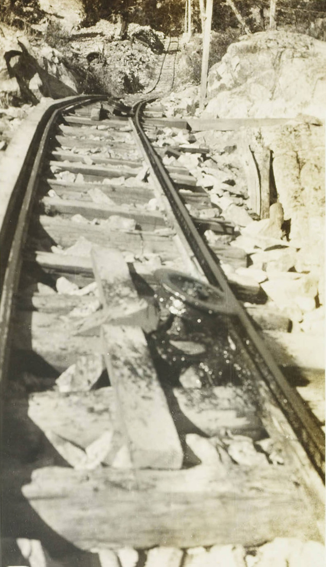
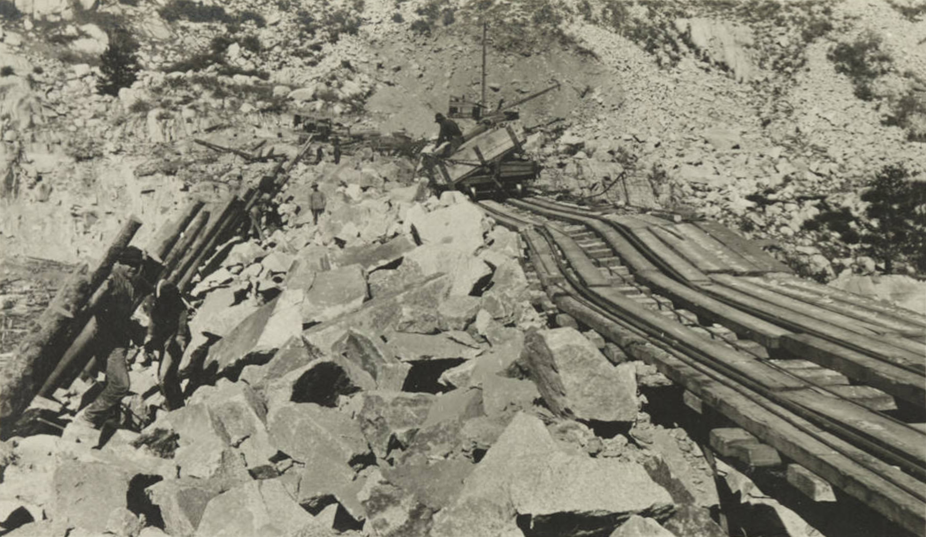
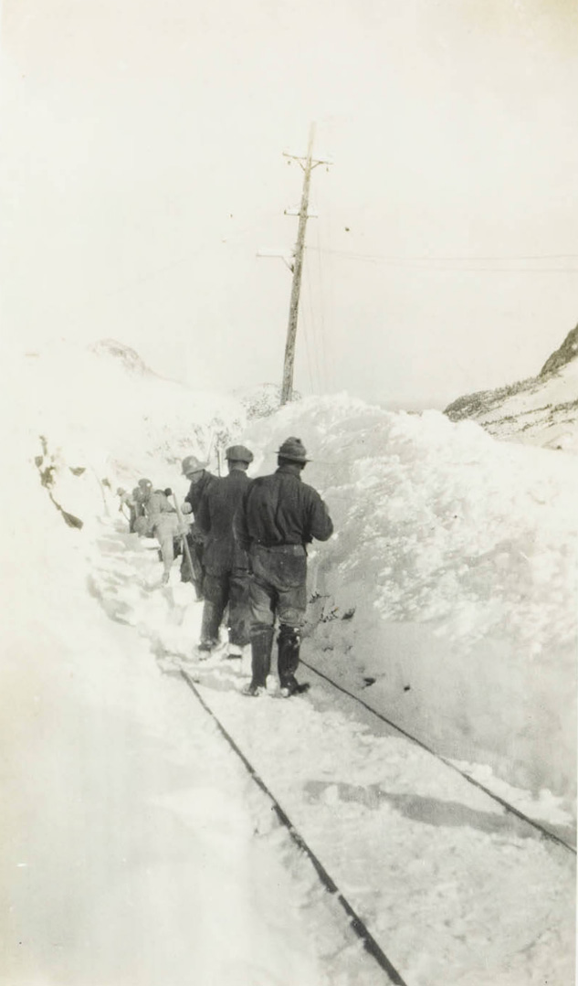 Clearing the tracks on Tram 1 after a severe snow storm |
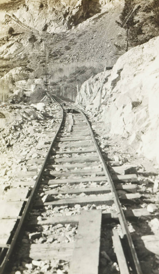 Tram 1 showing the styles of angle sheaves, spools and rollers and the rope threaded on them |
 Tram 1 showing the styles of angle sheaves, spools and rollers and the rope threaded on them |
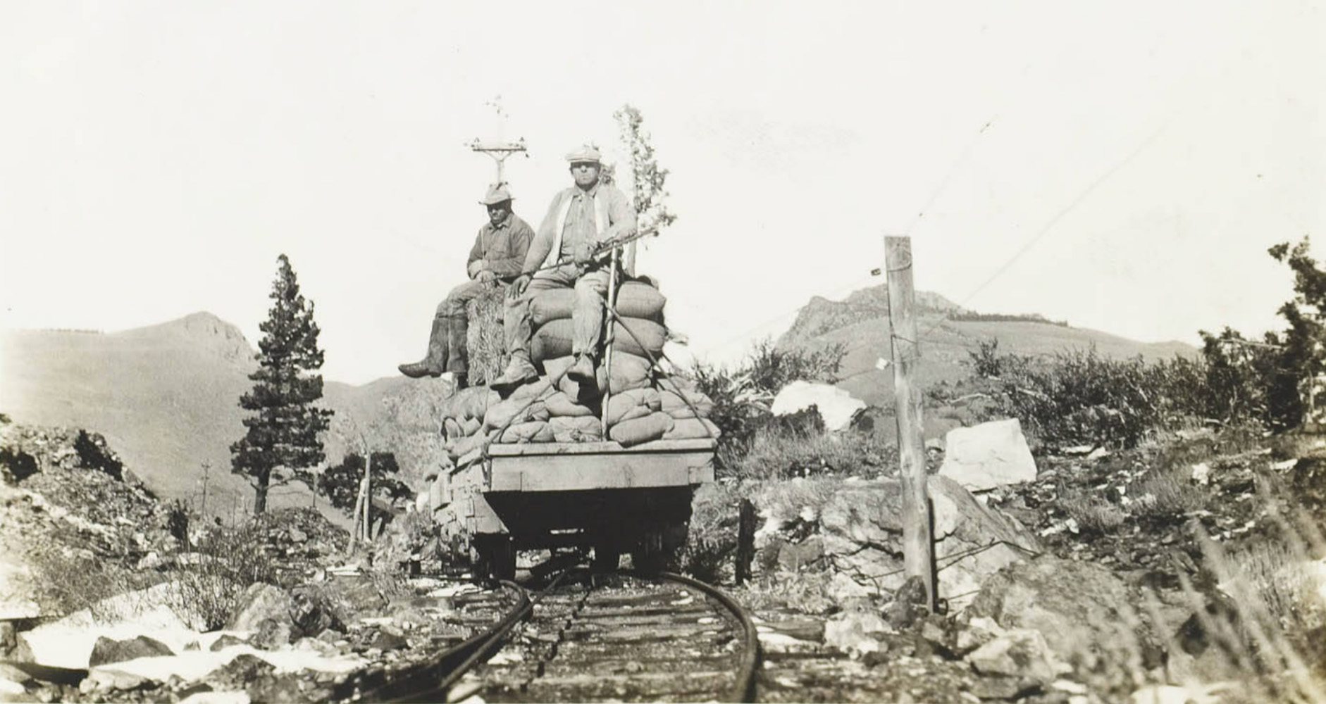 Tram car loaded with cement |
 Tramway #1 coming from the Silver Lake area |
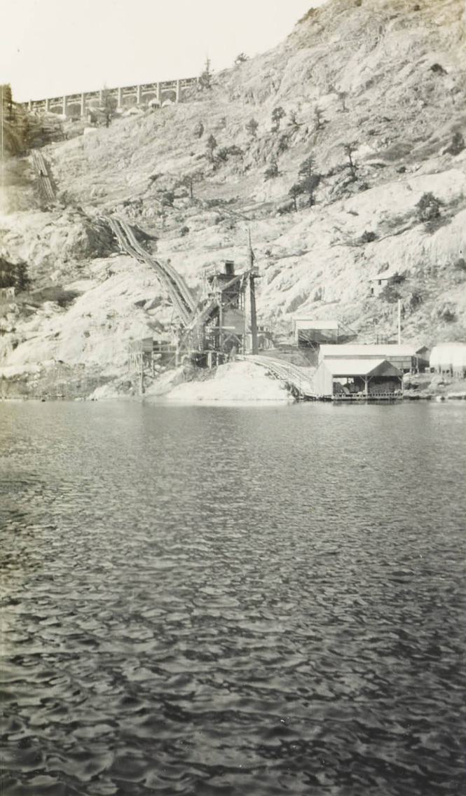 Tram 2 - 1715 lineal feet of inclined trestle from Agnew Lake to Gem Lake |
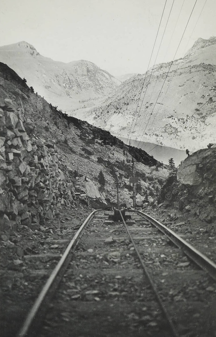
 Tram 2 running from Agnew Lake to Gem Lake |
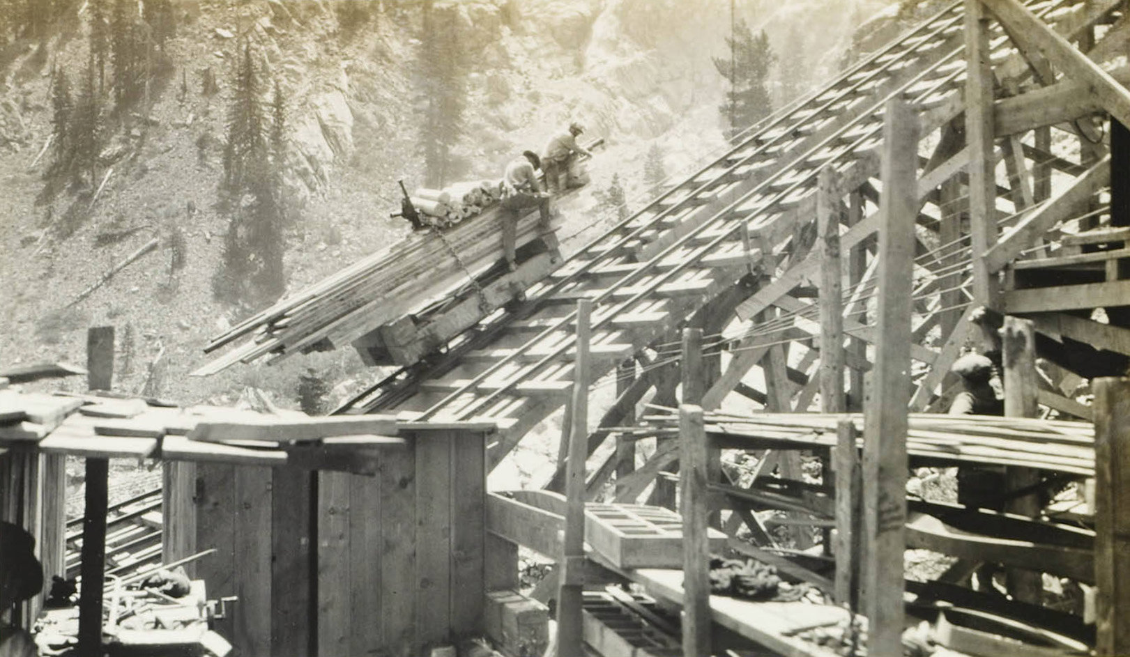 Lumber being transported up Tramway #2. The lumber was chained down to the body of the car and the chain was pulled tight by the use of a ratchet jack. |
|
 Station #14 on the tram |
 The tram at Aspen Flat |
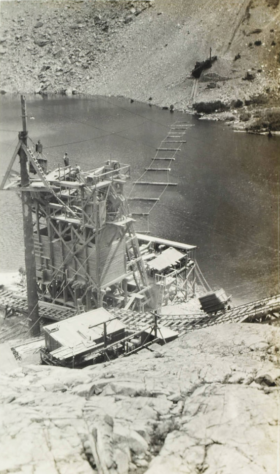
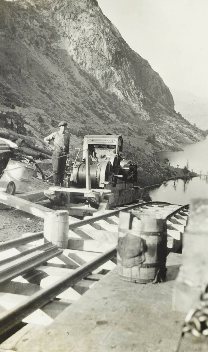 Gasoline driven double hoist used during construction of Tramway #2 |
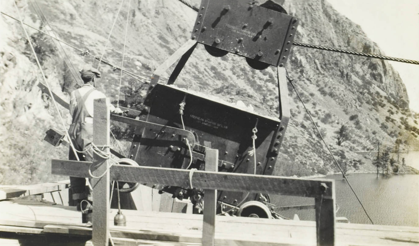
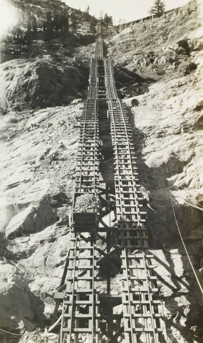 Tramway #2 showing a rock car. The all steel aggregate car being hauled up Tramway #2 weighed 3000 lbs and had a capacity of 4 cubic yards of rock. An average of four trips an hoiur were made under maximum operating conditions . |
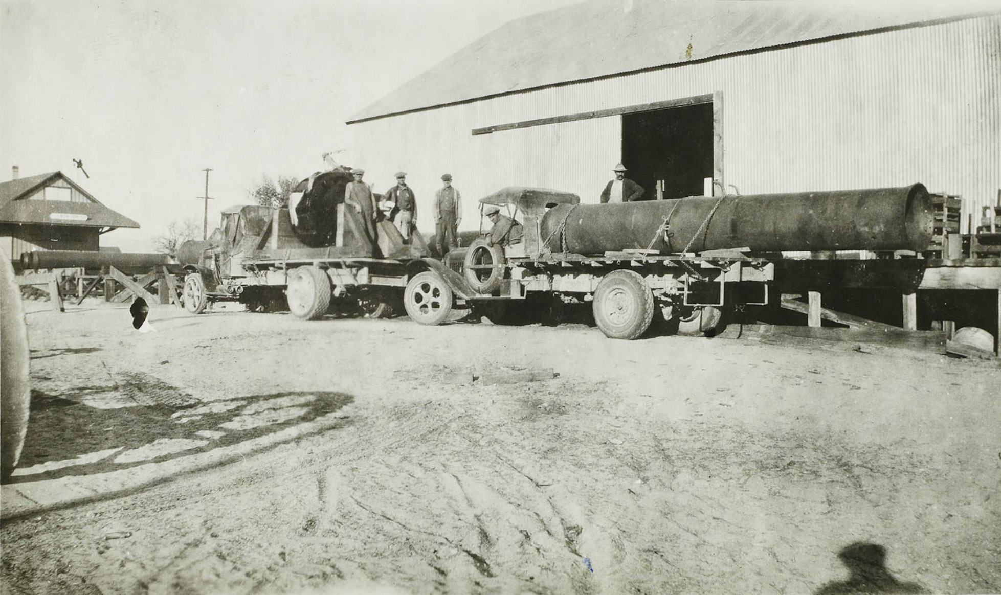
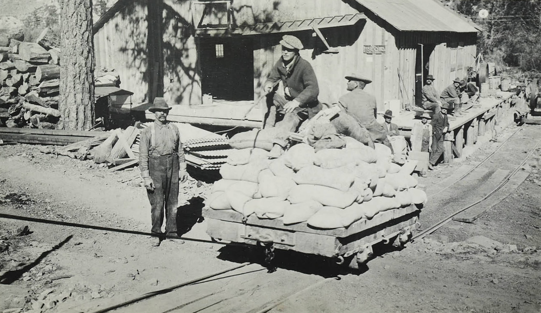
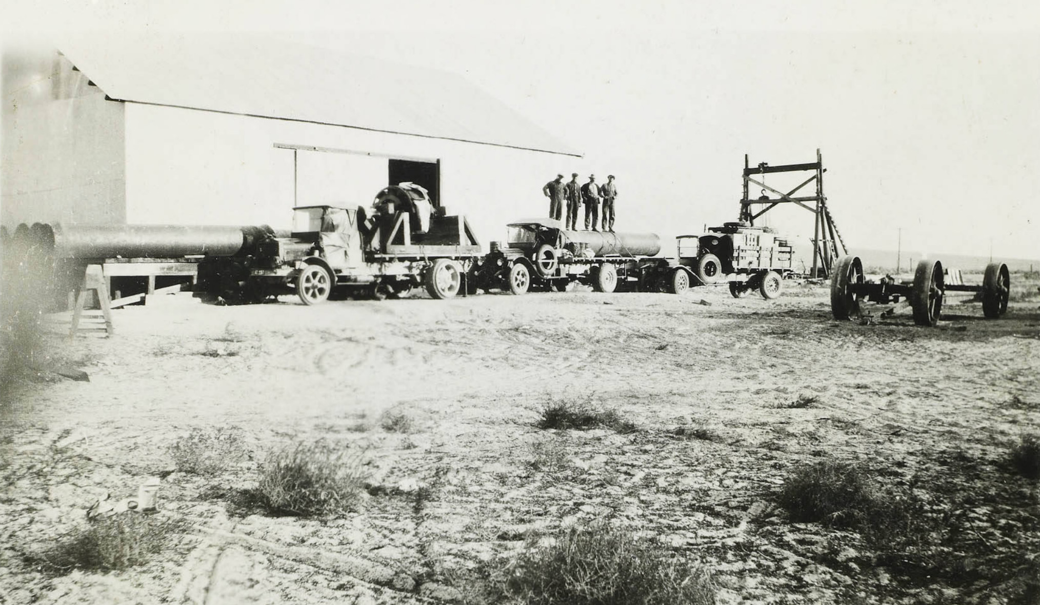 Hauling equipment from the SPNG station at Benton to Rush Creek PH |
 Hauling equipment from the SPNG station at Benton to Rush Creek PH |
 30" valve on its way from the SPNG depot in Benton to Rush Creek PH |
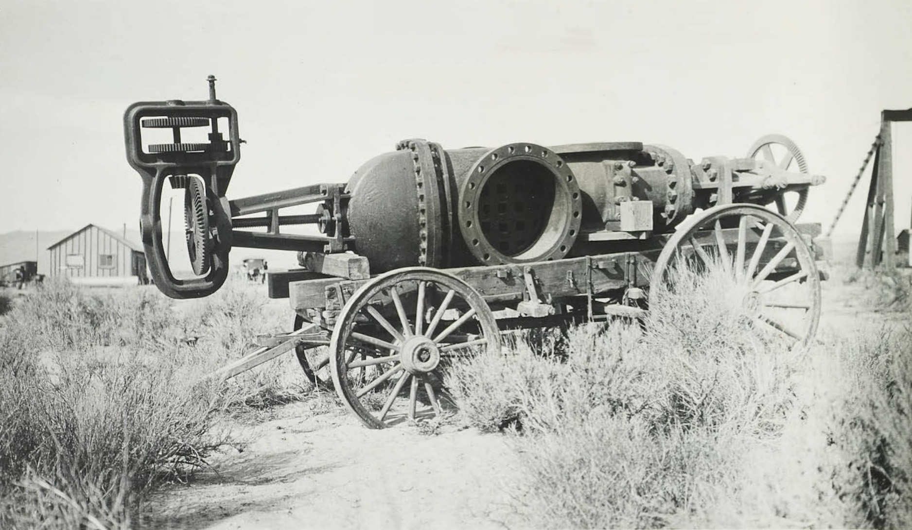
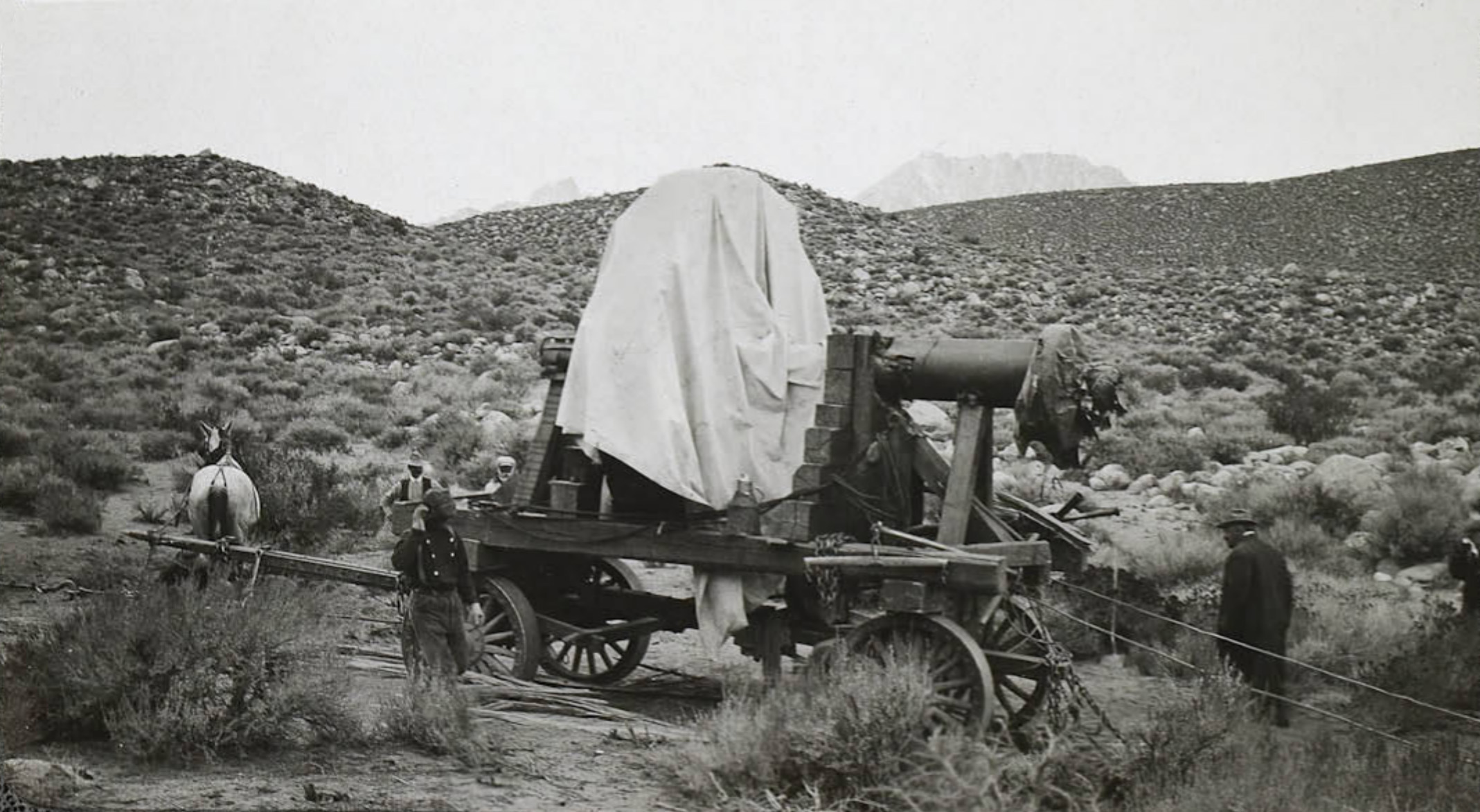
 Water wheel on its way from the SPNG depot in Benton to Rush Creek PH |
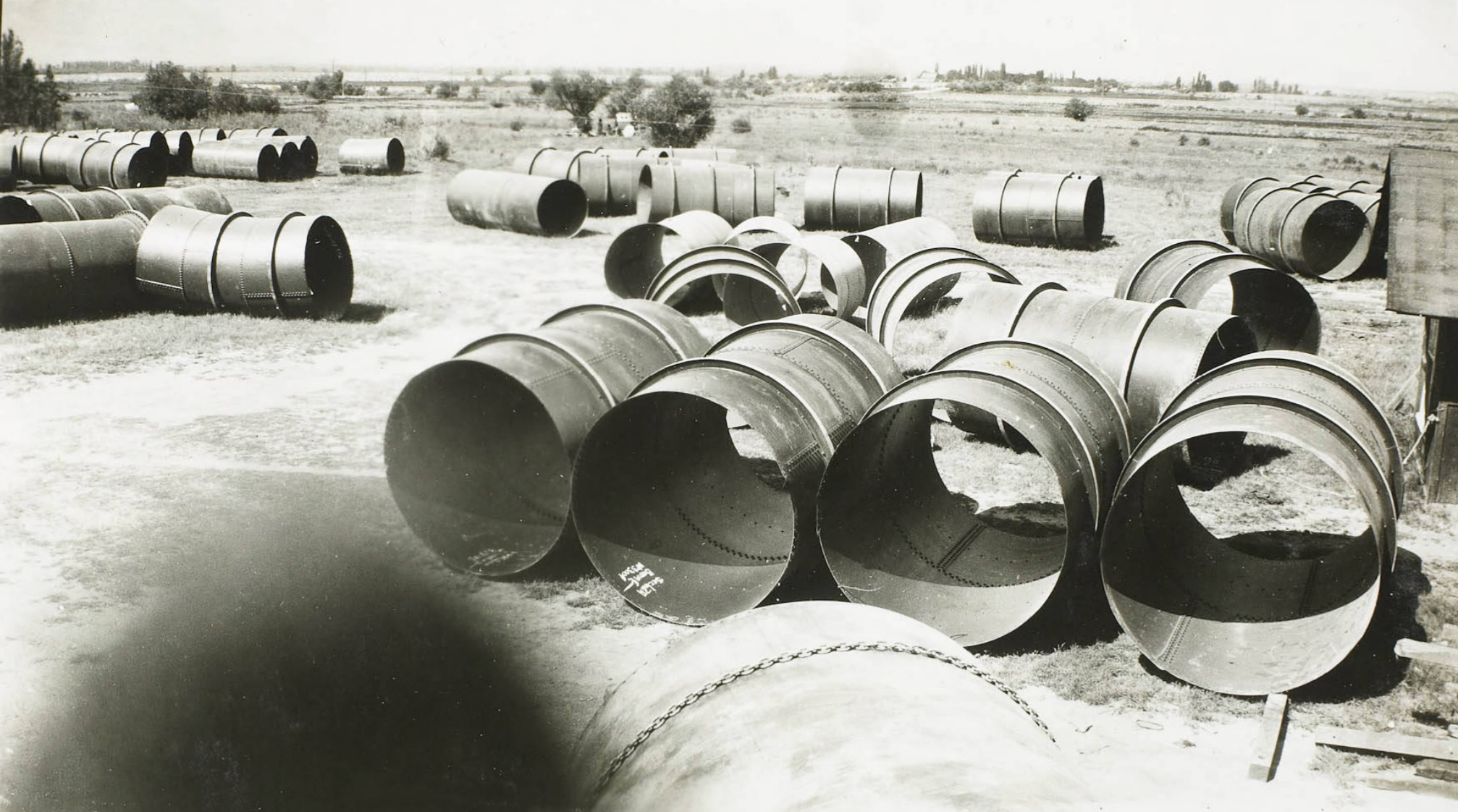
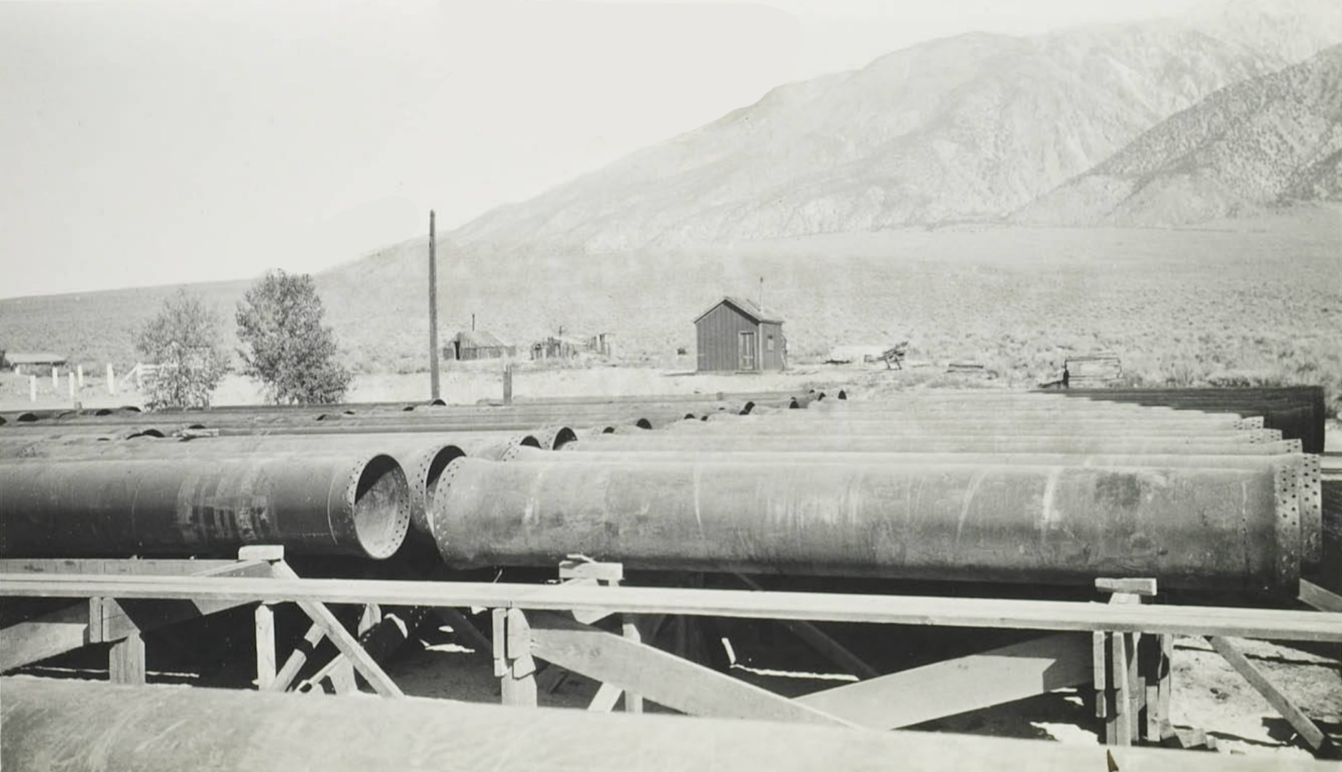 Steel pipe storage yard at Benton for Rush Creek PH |
 Transformer being hauled to the Rush Creek powerhouse at Silver Lake |
 Rush Creek Powerhouse construction |
 Rush Creek Powerhouse construction - 11-11-15 |
 A 7.5 ton 48" gate valve |
 Starting up the Rush Creek Tram with 3.5 tons of cement. |
 Grant Lake tent bunkhouse |
 Rounding a dangerous curve in the tram. |
 Greek rock crew waiting for dinner |
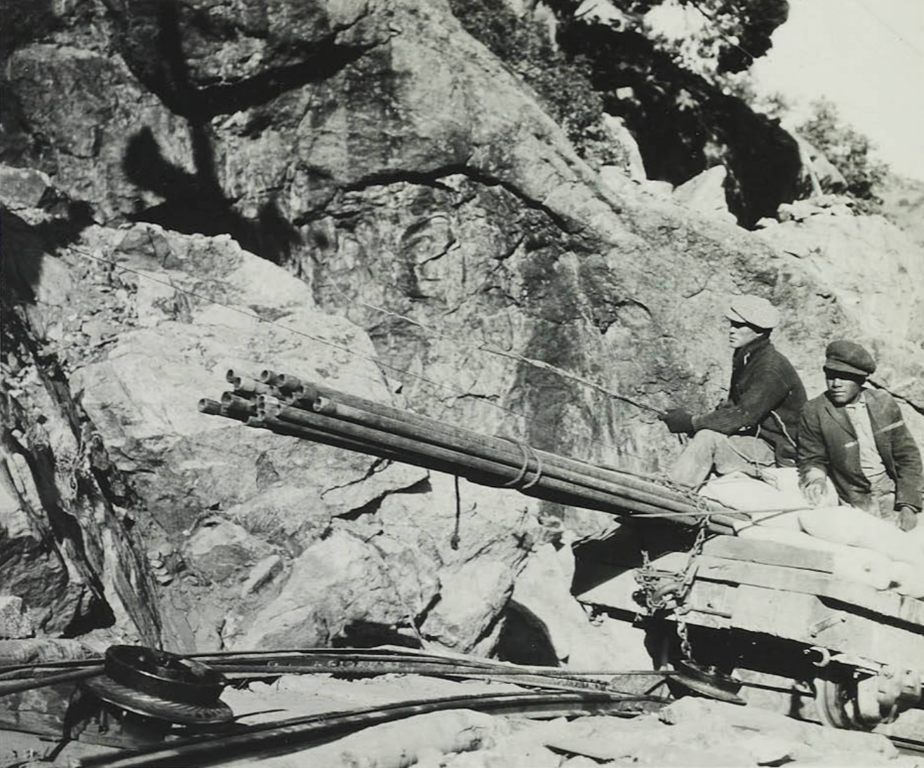
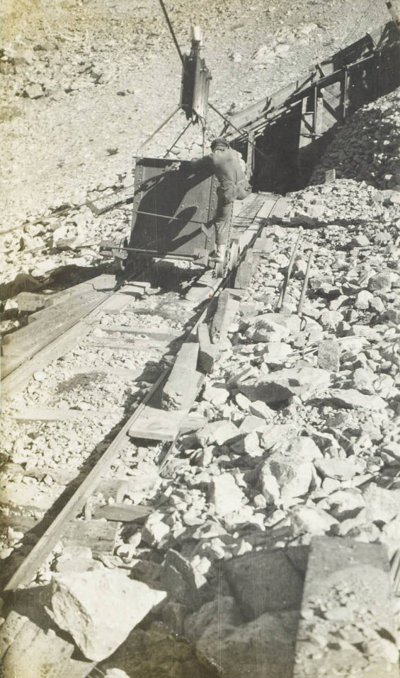
 Unloading pipe off of the tram |
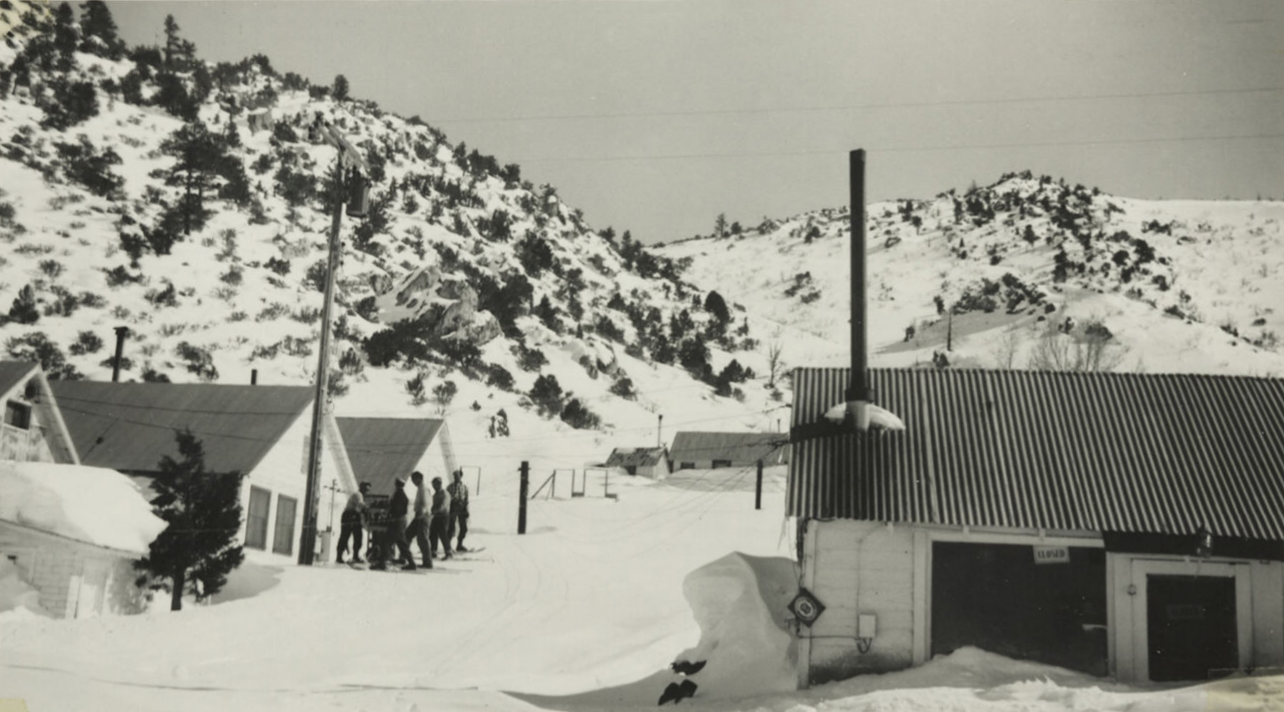
 Stopping for a break on the way to Silver Lake |
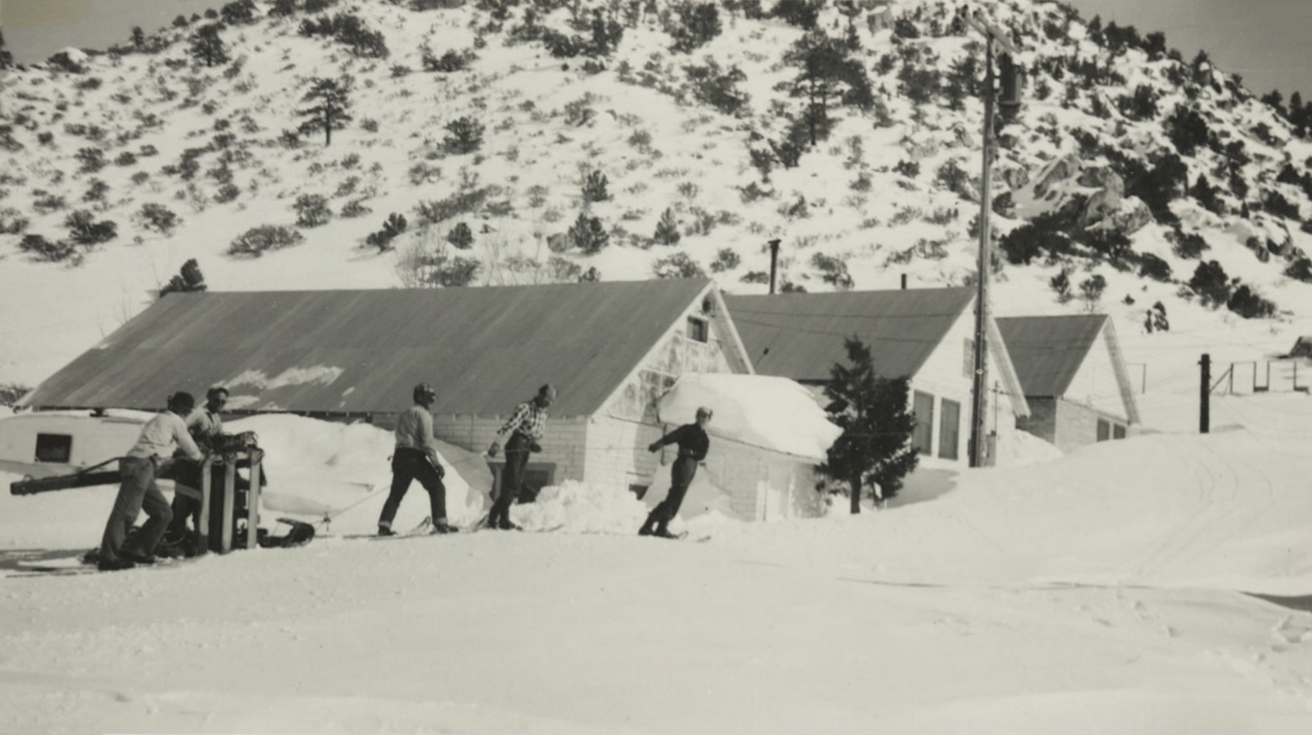
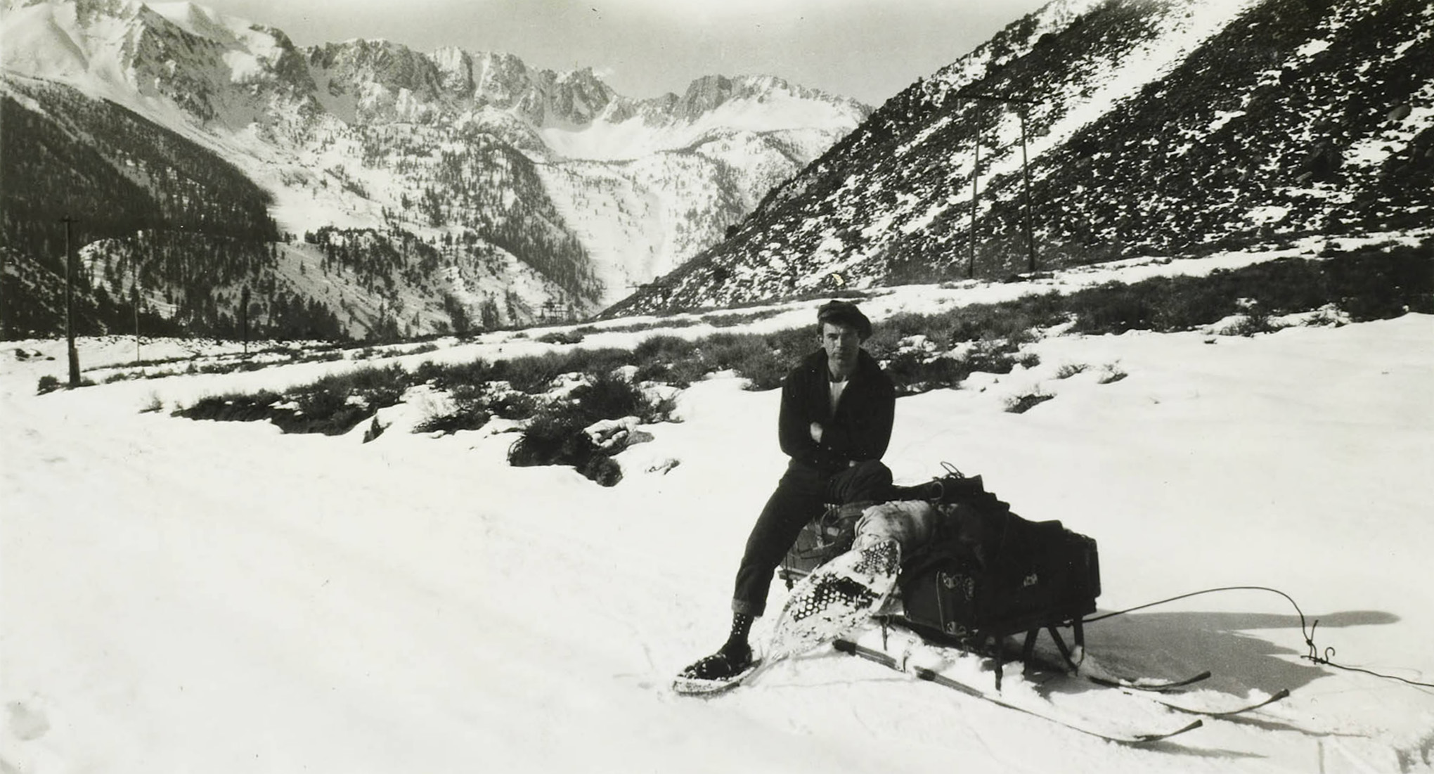 Heading to Silver Lake via snow shoes and sled |
 On the road to Silver Lake |
|
 Tractor hauling materials at Silver Lake |
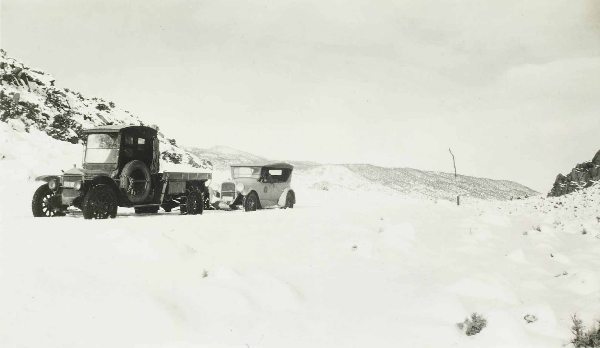
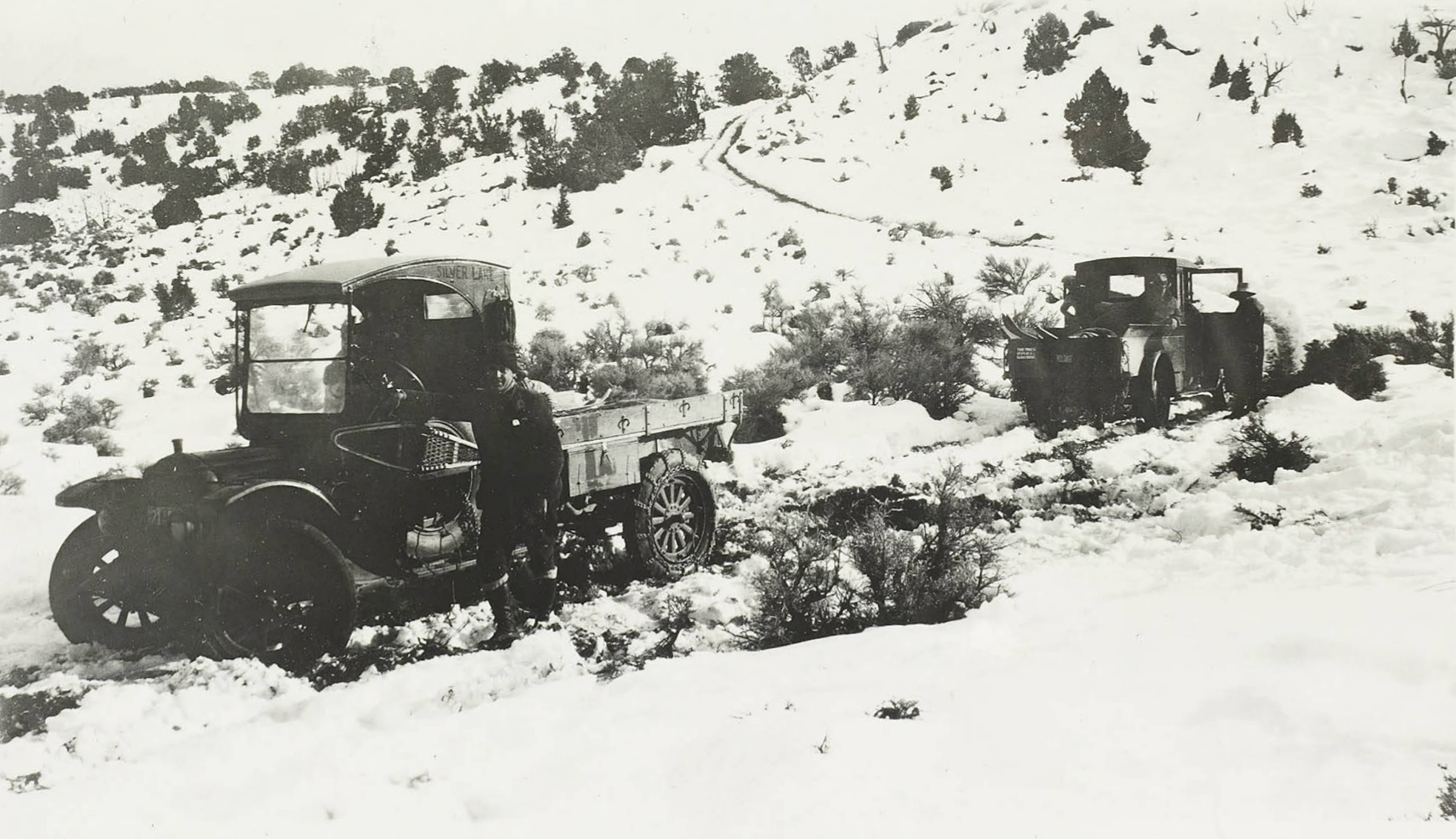 Winter traffic on the way to Silver Lake |
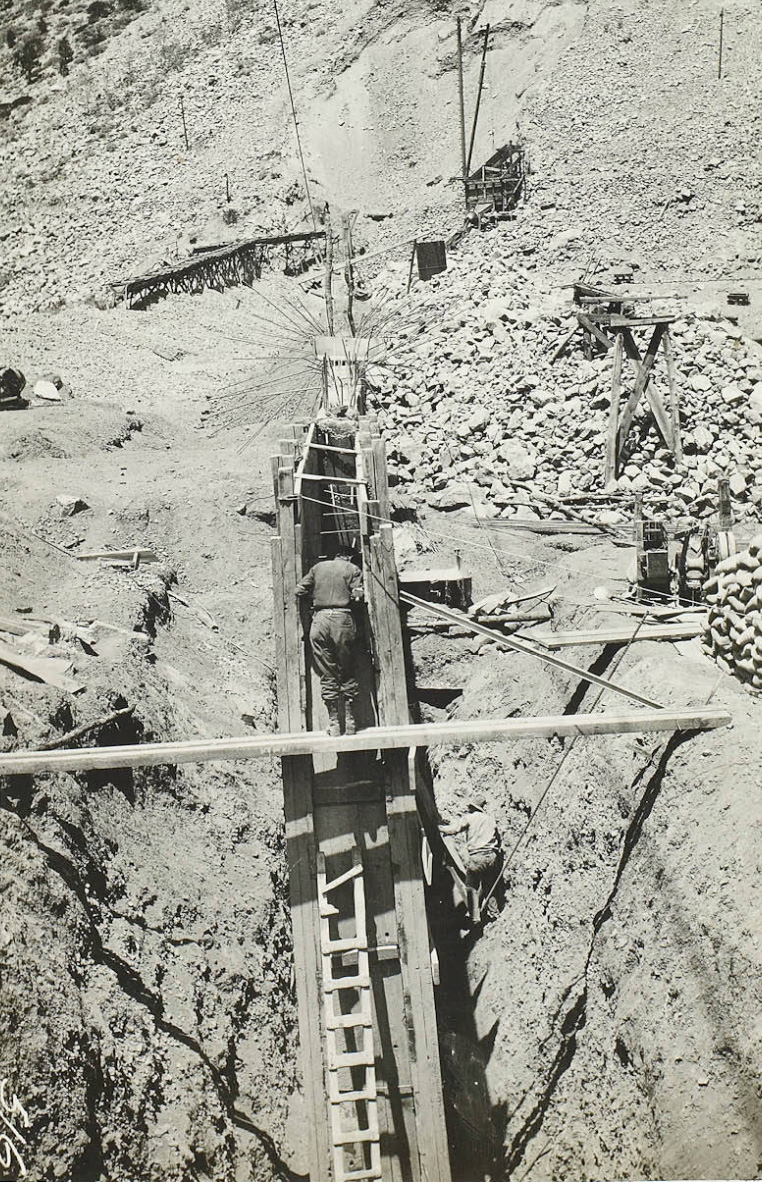
 Agnew Dam construction |
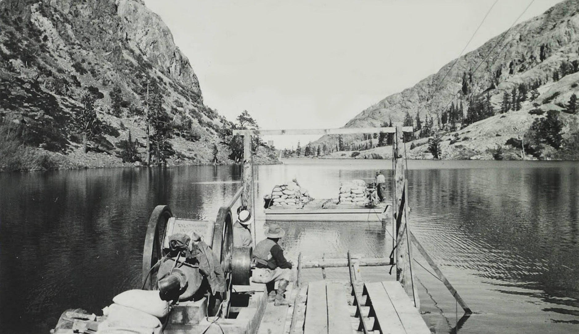 Agnew Lake portage |
 Agnew Lake tram |
|
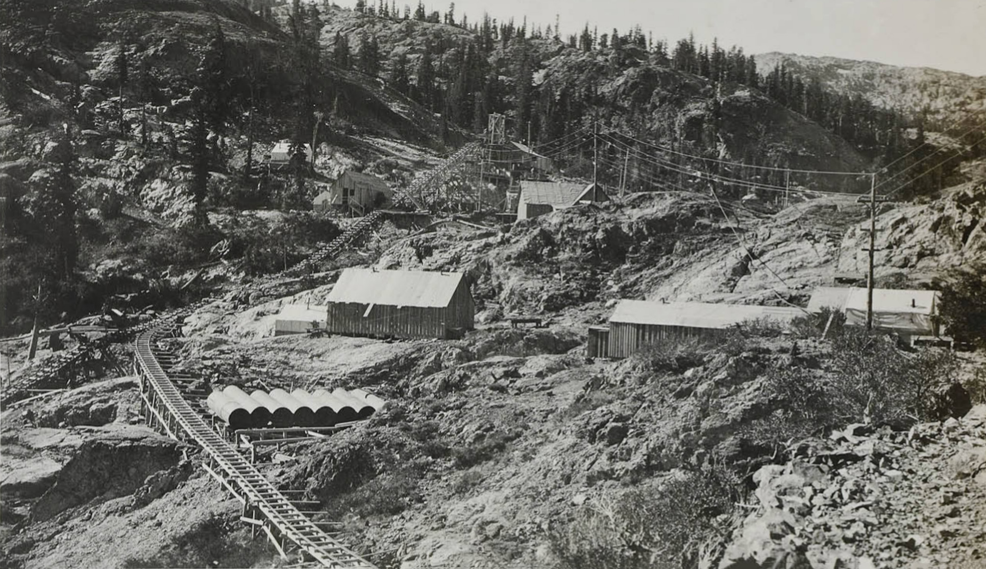
 Concrete plant and trestle on Gem Lake dam construction |
 Gem Lake dam construction camp |
 Gem Lake Dam construction |
 Gem Lake Dam construction |
 Gem Lake Dam construction |
 Gem Lake Dam construction |
 Gem Lake dam construction |
 Gem Lake dam construction |
 cabelway car in the dumping position at the crushing plant |
 Gem Lake dam site |
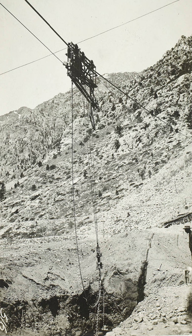
 Cableway between the rock pit and the crushing plant |
 Cableway car |
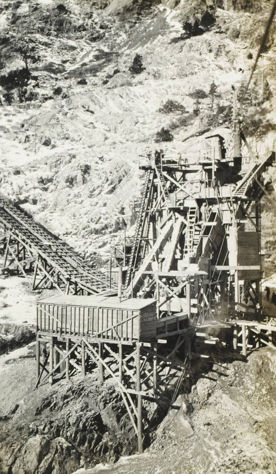
 Crushing plant bunkers |
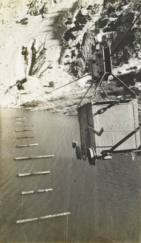
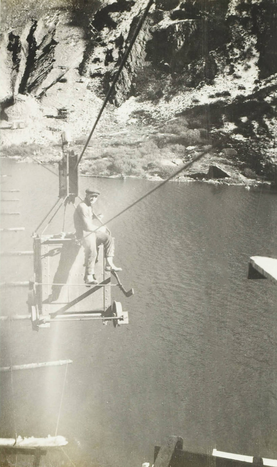 Cableway car over lake |
 Rock crushing plant |
|
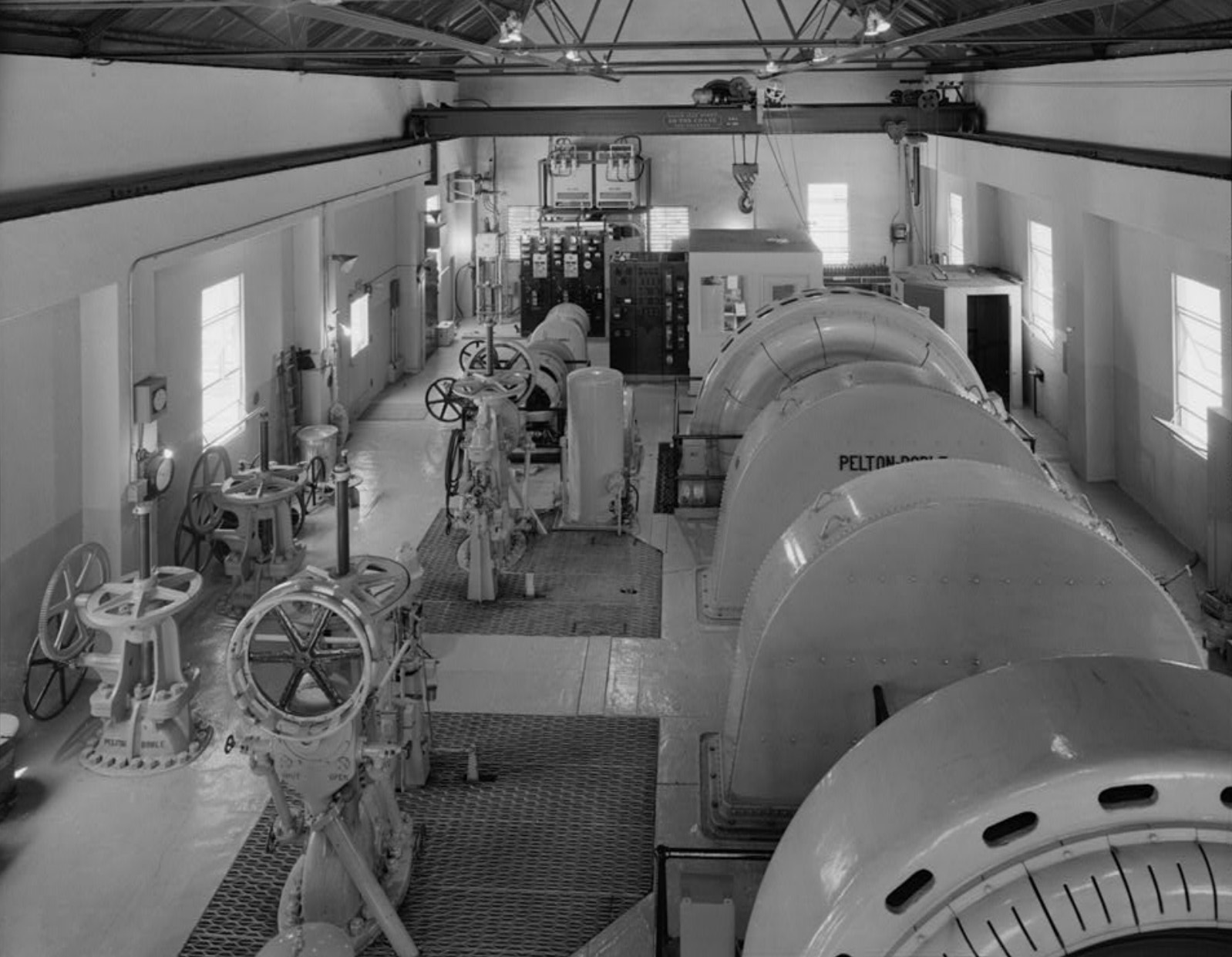 Rush Creek Power Plant Interior of powerhouse generator room showing generator units at foreground right, governors and control valves (Photo and text courtest Library of Congress) |
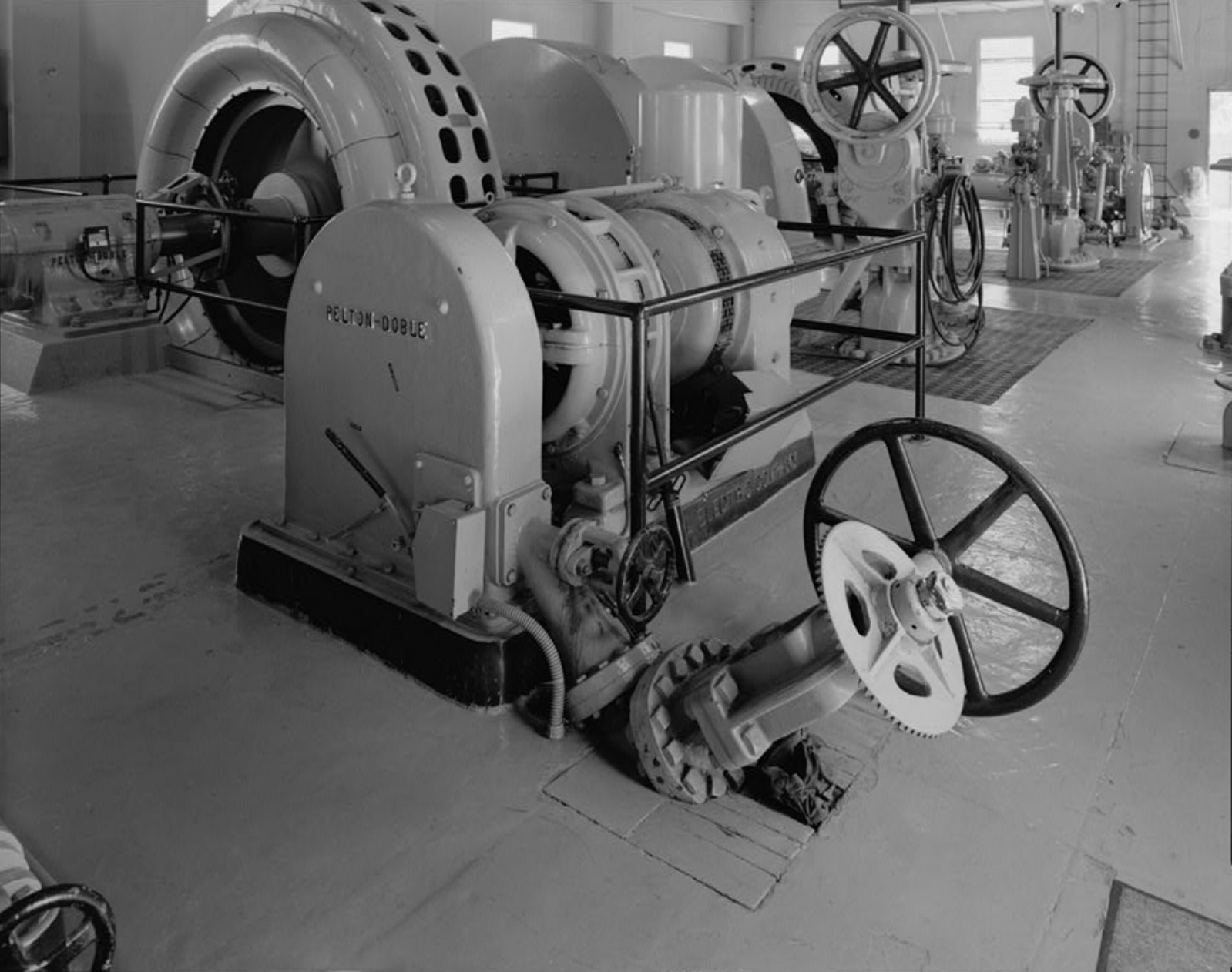
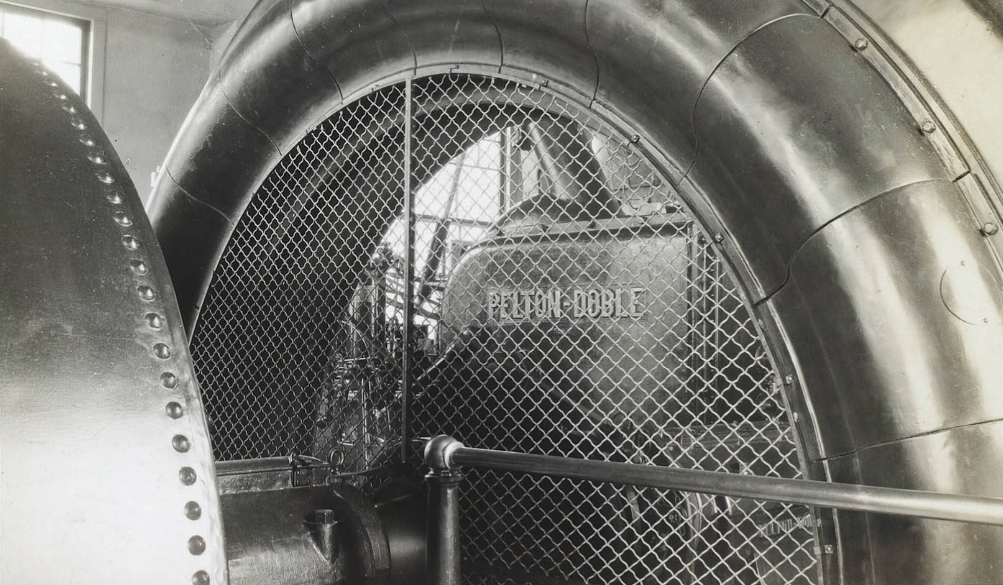
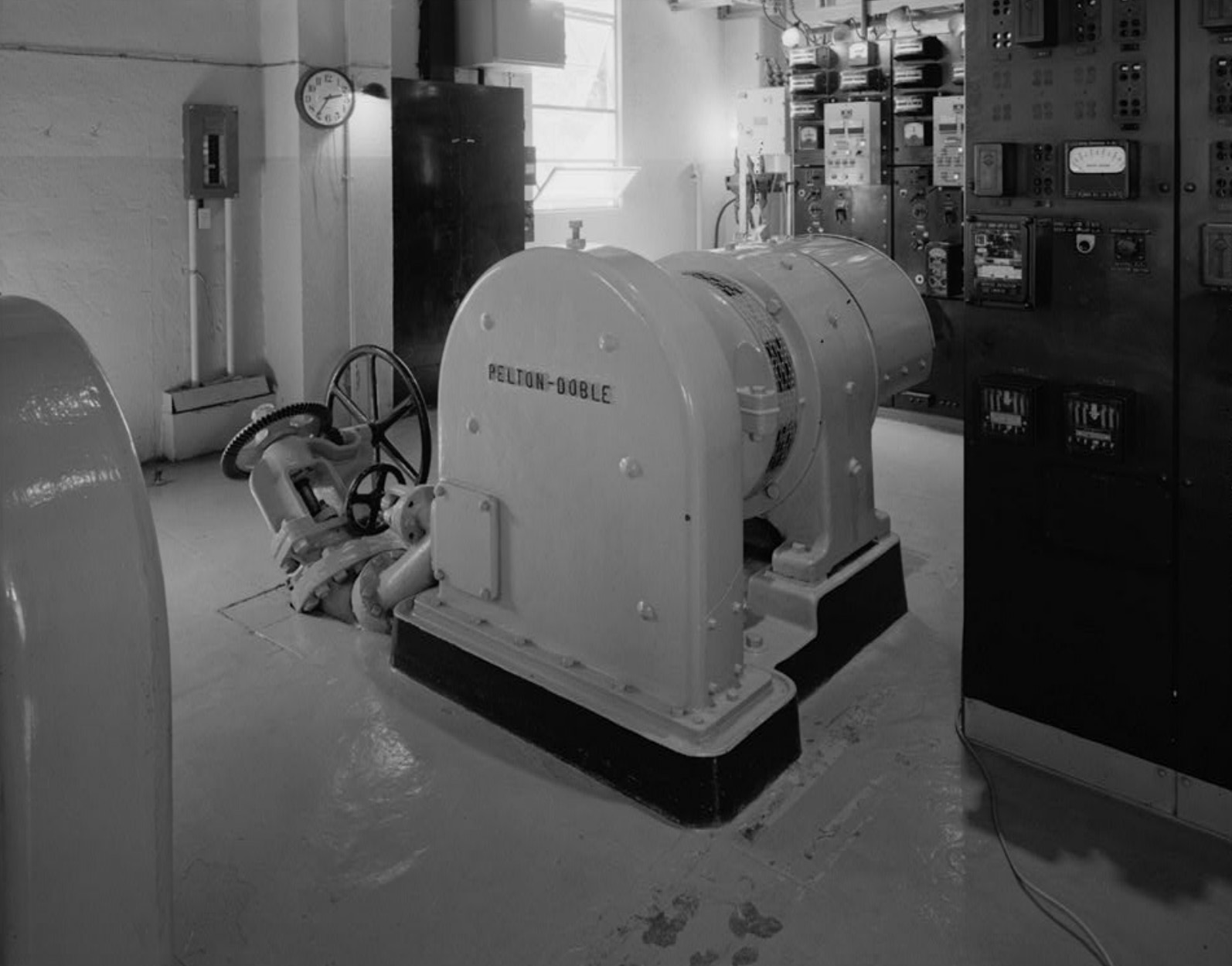 Rush Creek Power Plant Powerhouse interior showing exciter No. 1. Small Pelton-Doble impulse wheel in foreground (Photo and text courtest Library of Congress) |
 Rush Creek Power Plant Powerhouse interior showing exciter No. 1. Hand-controlled gate valve shown on nozzle to Pelton_Doble impulse wheel (Photo and text courtest Library of Congress) |
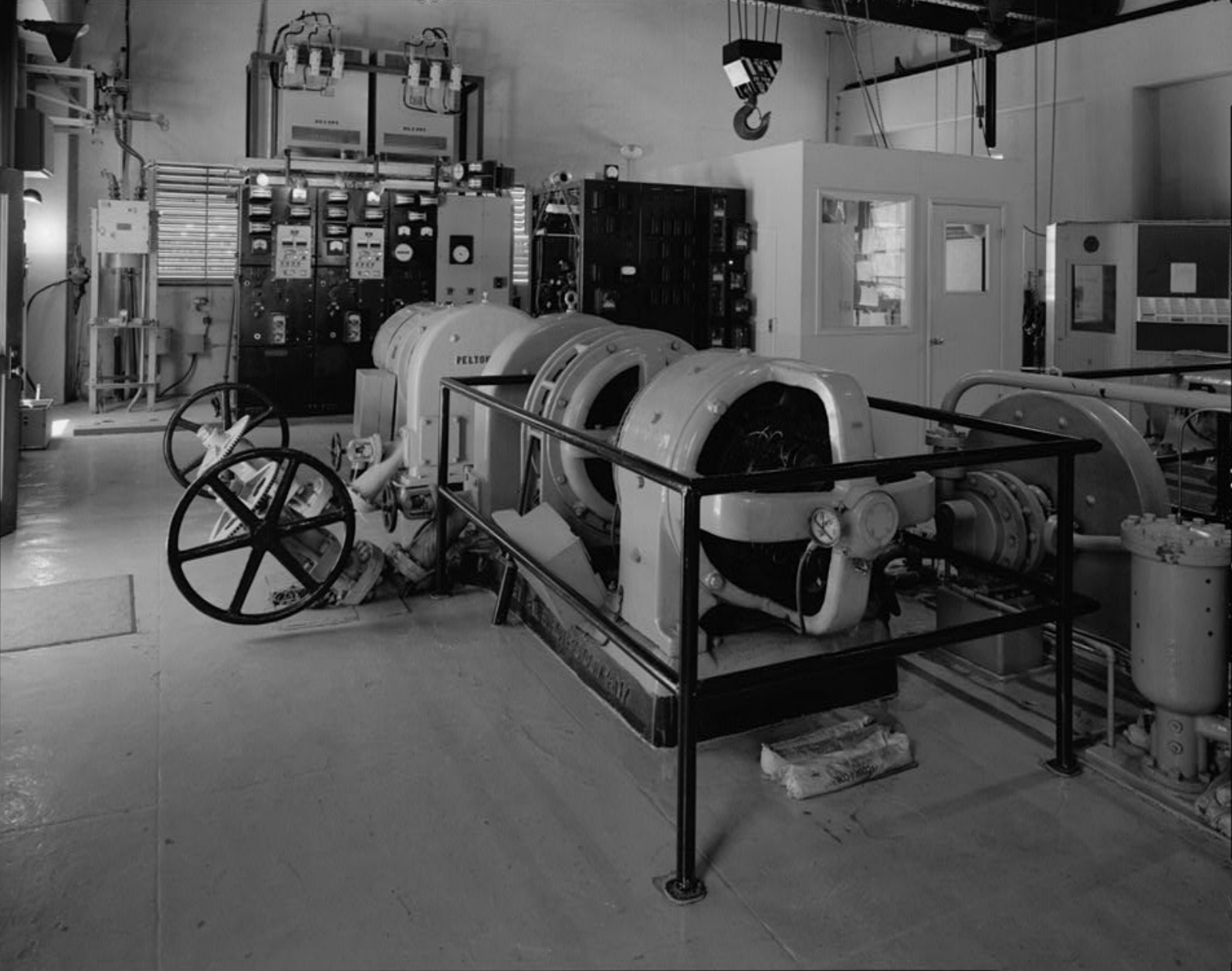
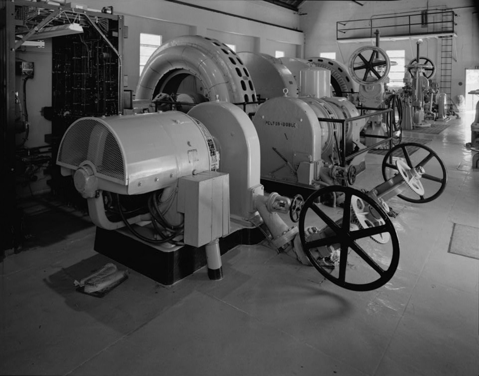 Rush Creek Power Plant Powerhouse interior showing exciter No. 1 in foreground, Exciter No. 2, and generator units behind (Photo and text courtest Library of Congress) |
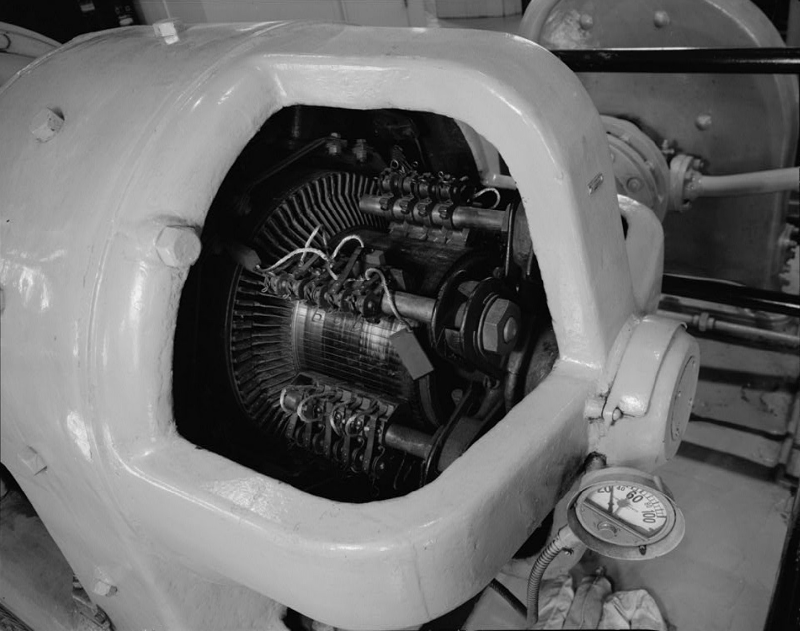 Rush Creek Power Plant Powerhouse interior, detail of Exciter No. 2 General Electric generator showing copper commutator and carbon brushes (Photo and text courtest Library of Congress) |
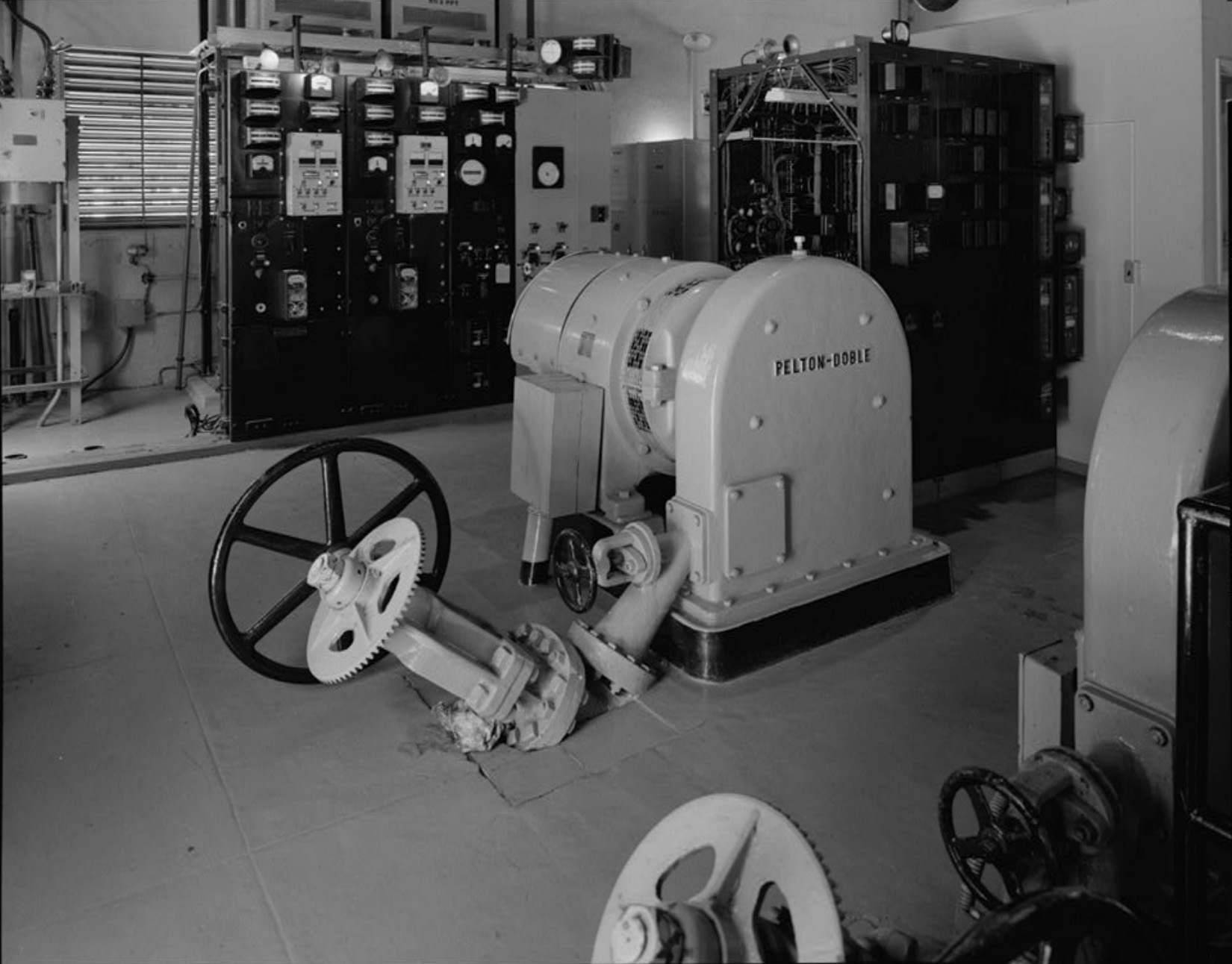
 Rush Creek Power Plant Powerhouse interior showing Exciter No. 2 small Pelton_Doble impulse wheel, hand-controlled gate valve, and nozzle. (Photo and text courtest Library of Congress) |
 Rush Creek Power Plant Powerhouse interior showing Exciter No. 2 with Exciter No. 1 behind overhead crane dangles at top of photo (Photo and text courtest Library of Congress) |
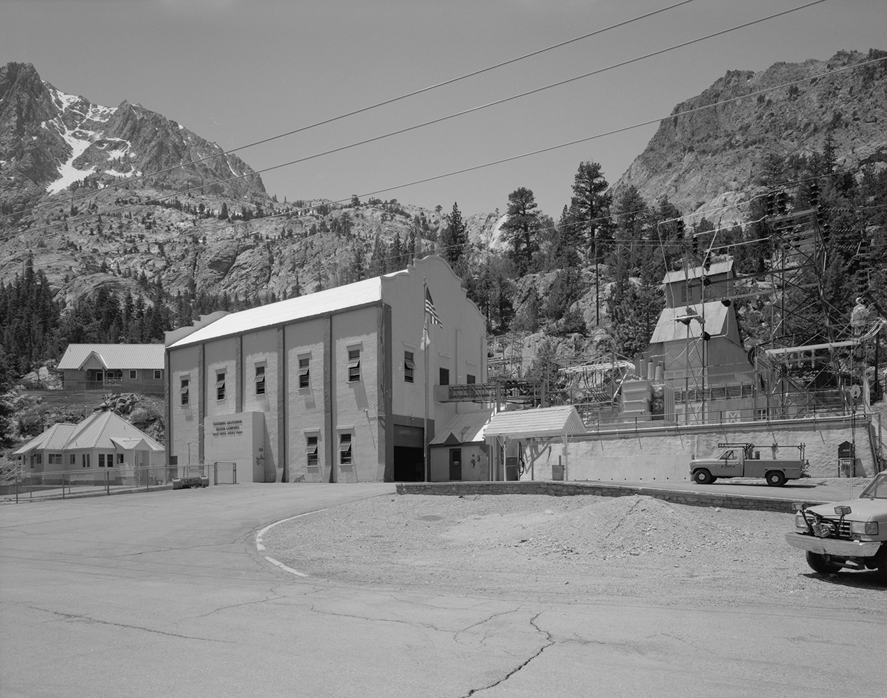 Rush Creek Power Plant East side/North end Exterior of Rush Creek Powerhouse (Photo and text courtest Library of Congress) |
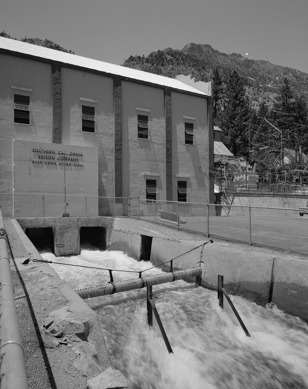 Rush Creek Power Plant East side exterior of powerhouse building showing tailrace (Photo and text courtest Library of Congress) |
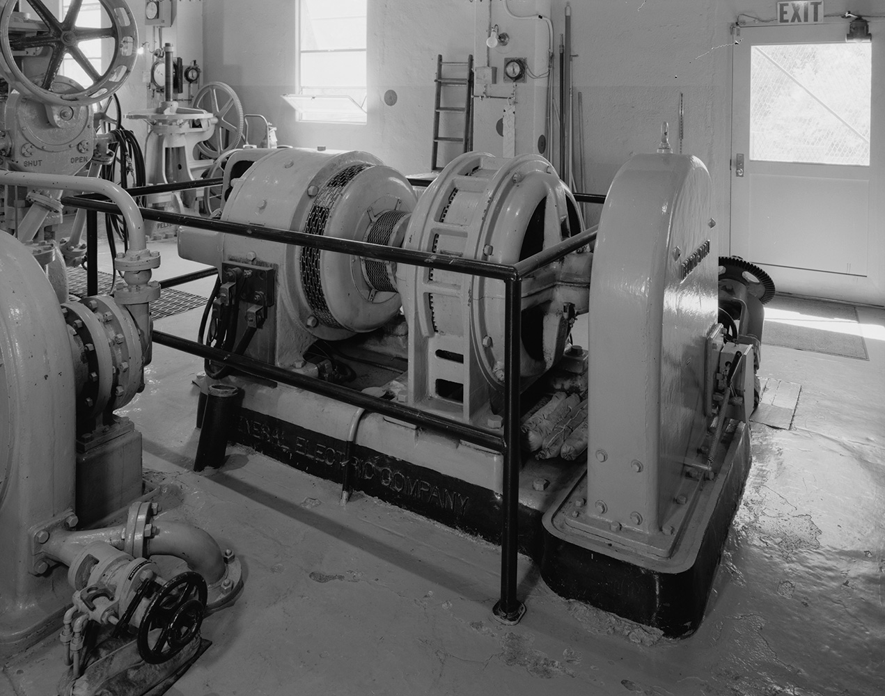 Rush Creek Power Plant Powerhouse interior, Exciter No. 2 showing General Electric induction motor in series between Pelton-Doble impulse wheel and General Electric generator (Photo and text courtest Library of Congress) |
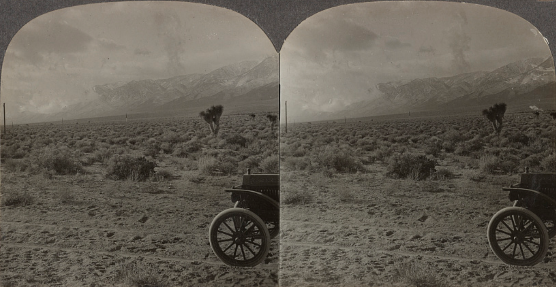 Stereogram of Sierra Nevada storm approaching the Rush Creek area (Photo and text courtest Library of Congress) |
|
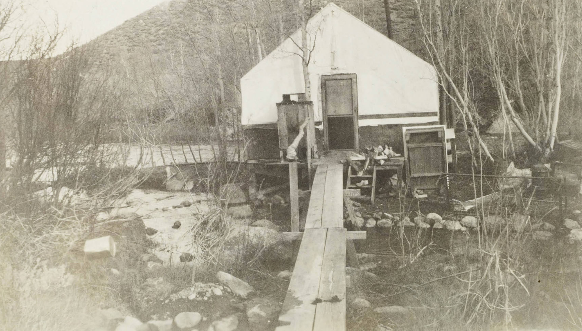
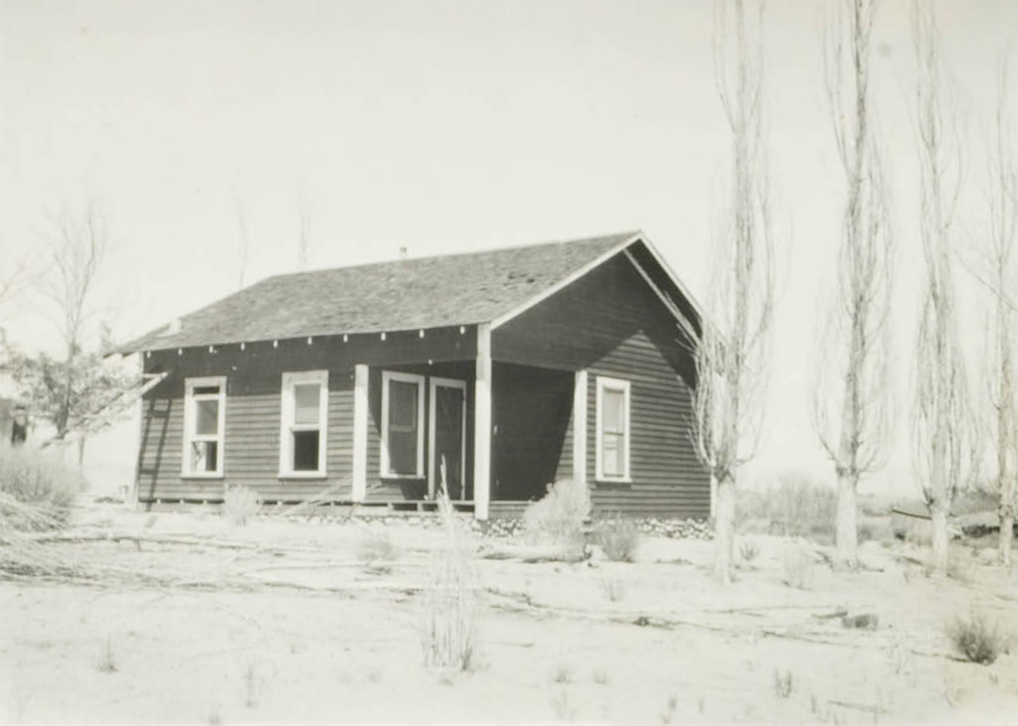
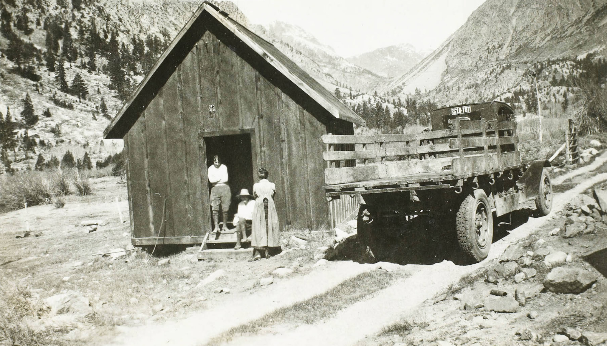 Dwelling on the way to the Rush Creek Power Plant |
|

Owens Gorge Powerhouses Owens River |
|
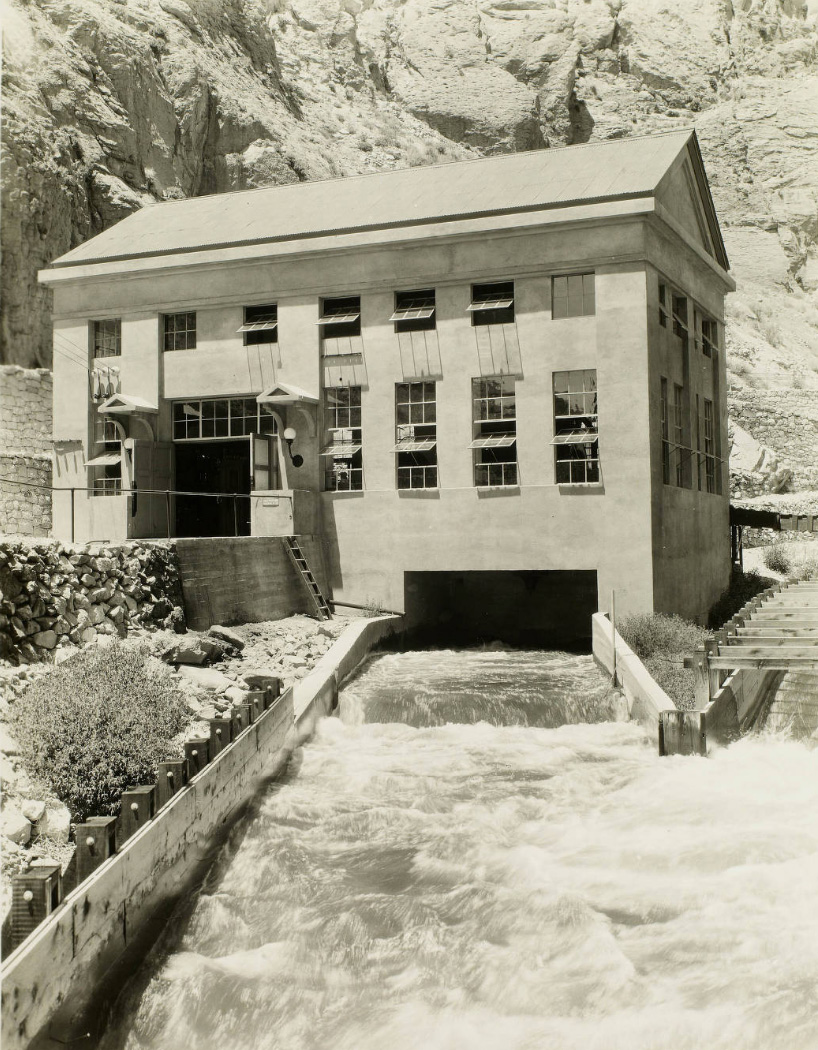
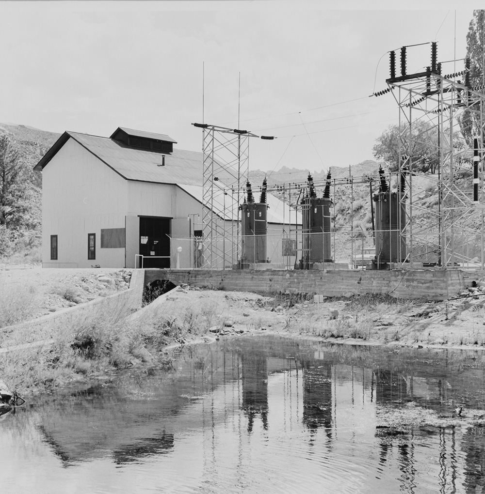
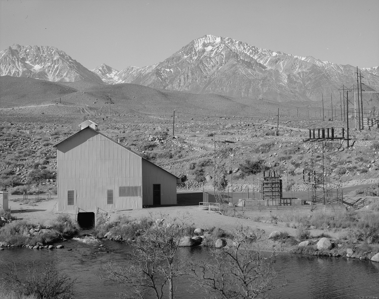
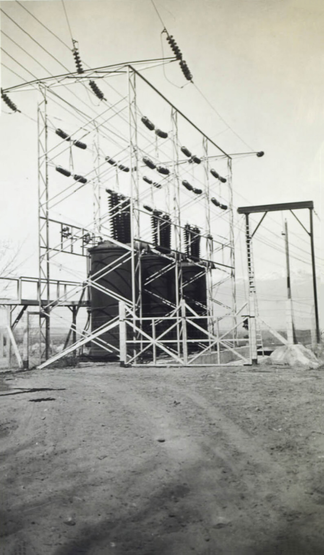
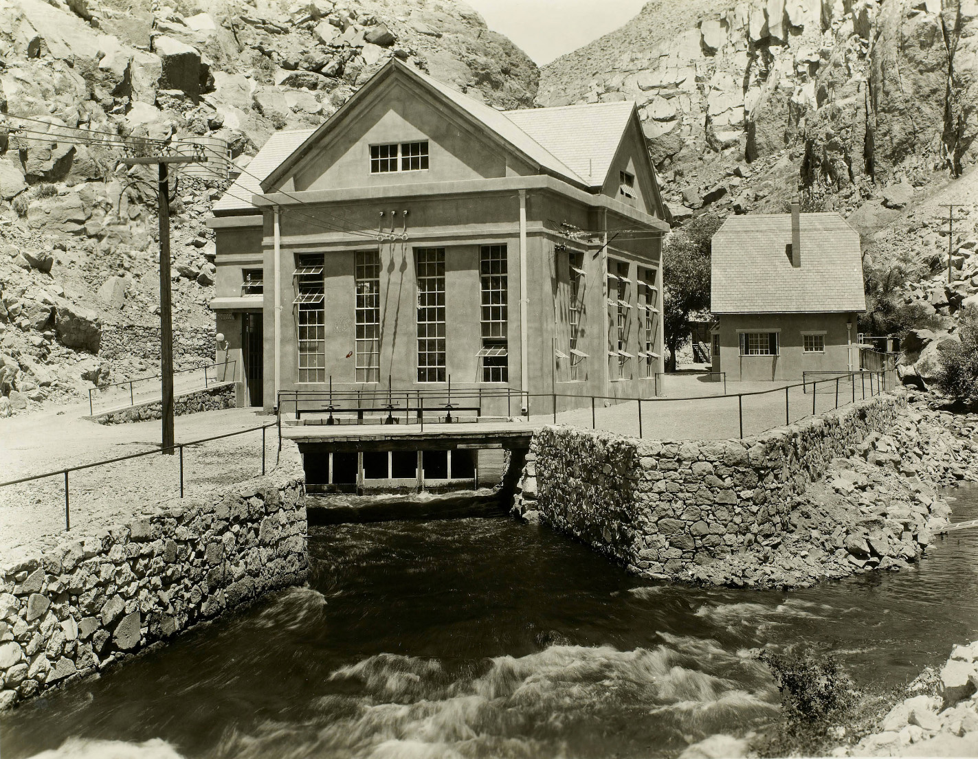 Adams Main Plant This is a stream flow plant, to which water is supplied through 659' of Redwood flume and 3,214' of steel pressure pipe, varing in diameter from 7' to 6'. Power generated at the Adams Main Plant together with that received from the Adams Auxiliary Plant is transmitted to Control Station over a branch line connecting with the Northern Division Tie Line. The outdoor substation located at the Adams Main Plant includes a steel bus structure,lightning arrester and high voltage switching equipment in addition to the bank of 3,500 Kv-a transformers. |
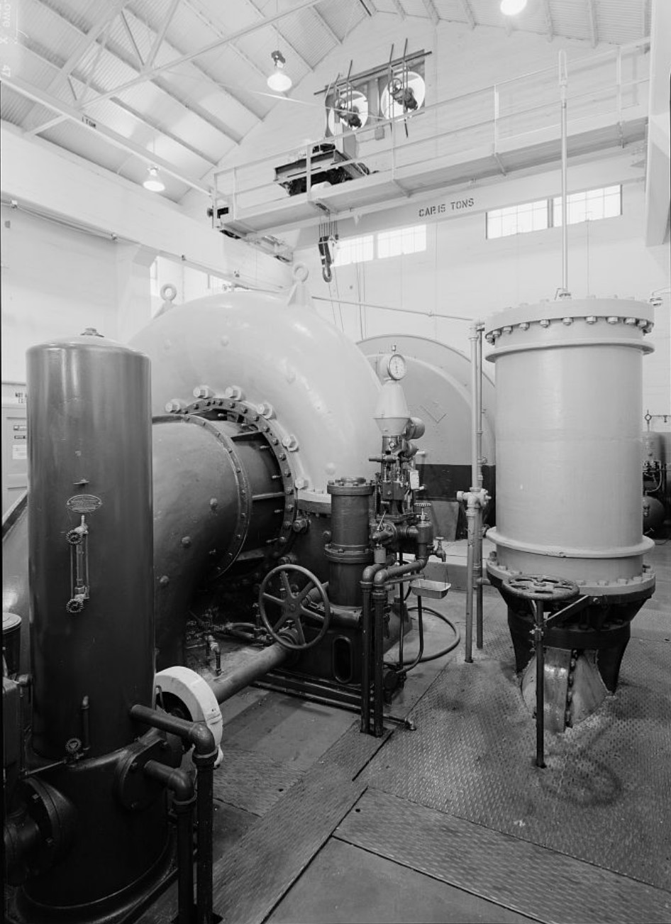
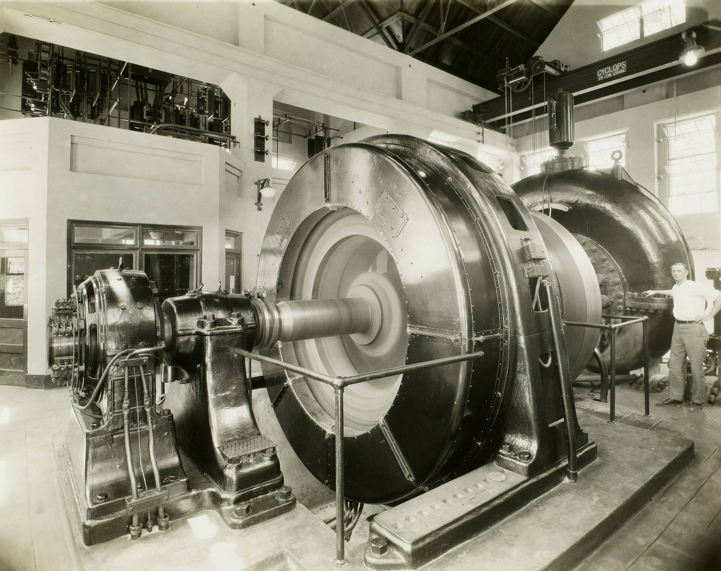 Adams Plant interior The hydraulic installation consists of one 7,500 horsepower, 400 RMP reaction turbine complete with oil pressure governor equipped with electric remote speed control, load limit attachment, electric solenoid automatic closing trip, governor actuated balanced piston type relief valve, flywheeel, and miscellaneous equipment. The electrical installatiion consists of one 6,250 Kv-a., 6,600 volt alternating current generator direct-connected to the turbine and with the exciter mounted on the same shaft as the generator. All of the 6,600 volt busses together with the various oil circuit breakers and disconnecting switches, potential and current transformers, as well as the local transformers for power and light are mounted on the mezzanine floor above the operating room. |
 Interior Owens River Plant |
 7.5' diameter pipeline at the Owens River Plants |
 Adams Auxiliary Plant |
 Owens River Adams Plant dwellings |
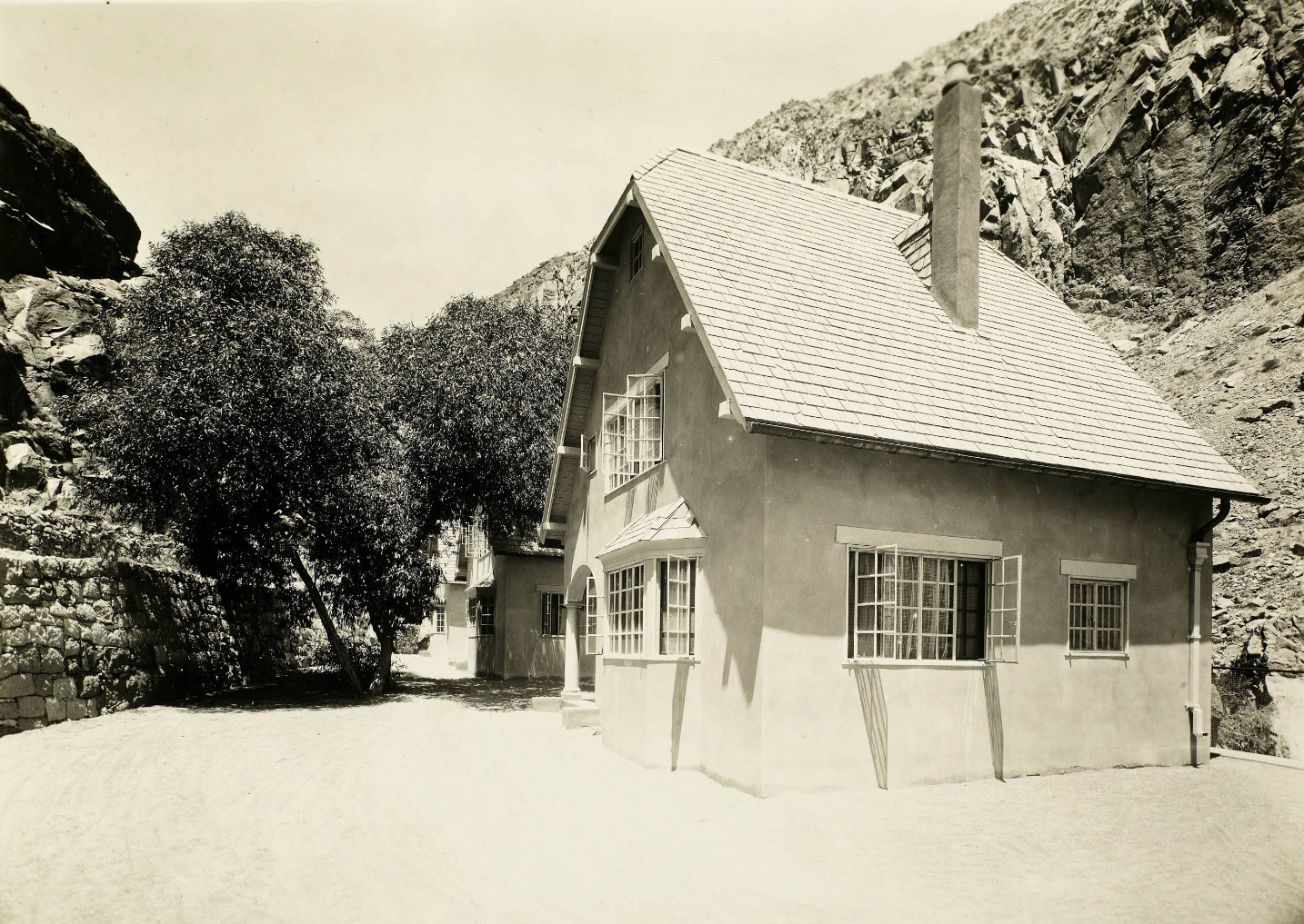 Adams Main Plant Cottages - Owens River Gorge |
 Adams Auxiliary Plant This is a stream flow plant, water being supplied from the Intake through 370' of flume, 455' of Redwood stave pipe and 664' of steel pressure pipe. The flume is 12' wide and 5' deep. The wood stave pipe is 6' in diameter and the steel pipe is 5.5' in diameter. The generating equipment installed in the powerhouse consists of a 3,750 horsepower reaction turbine direct-connected to a 3,000 Kv-a alternating current generator. Power generated at this Plant is transmitted to the Adams Main Plant, located downstream and supplemented with the power generated at the Adams Main Plant is stepped up to transmission voltage through a bank of transformers located at the Adams Main Plant. |
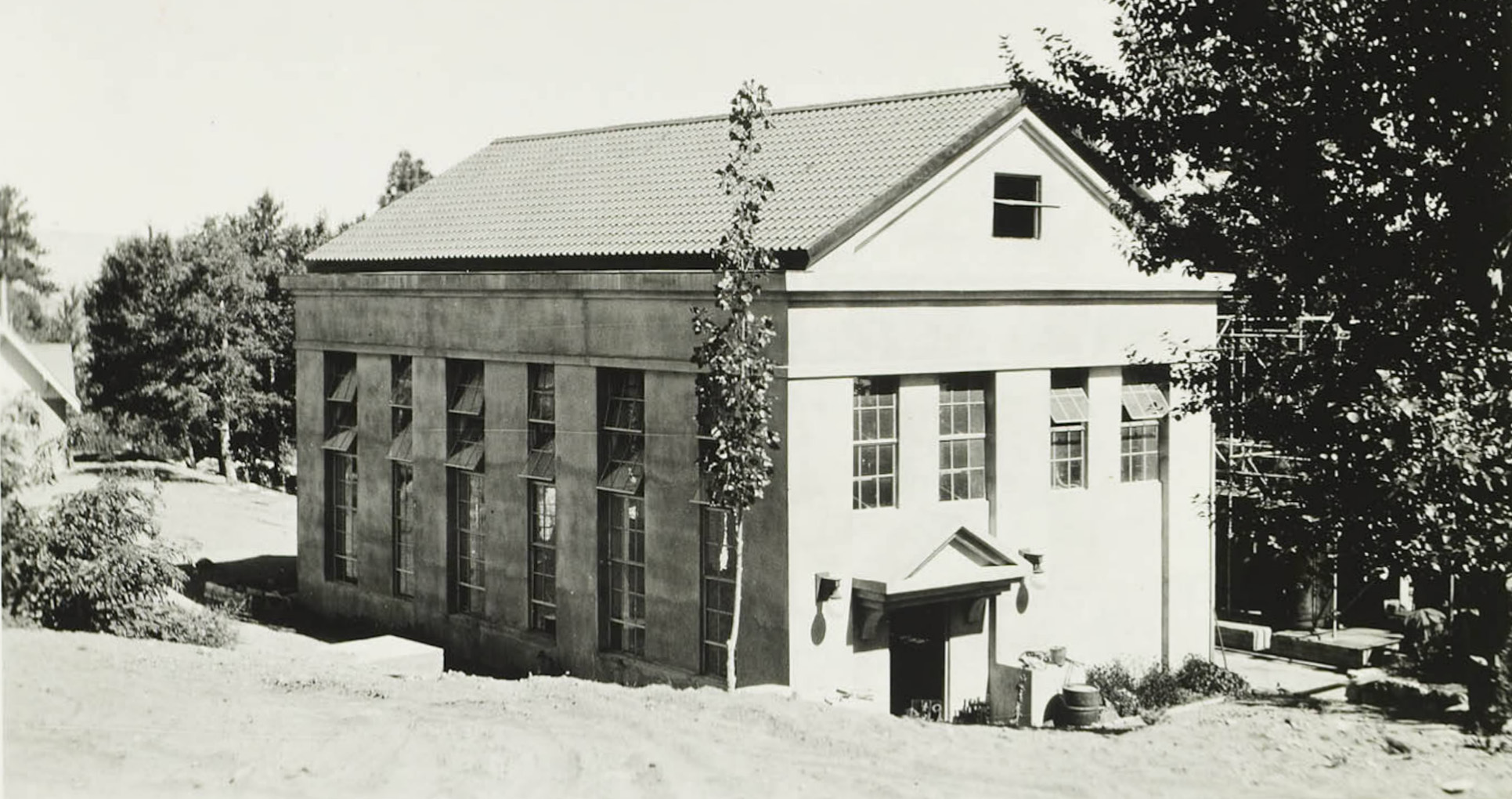
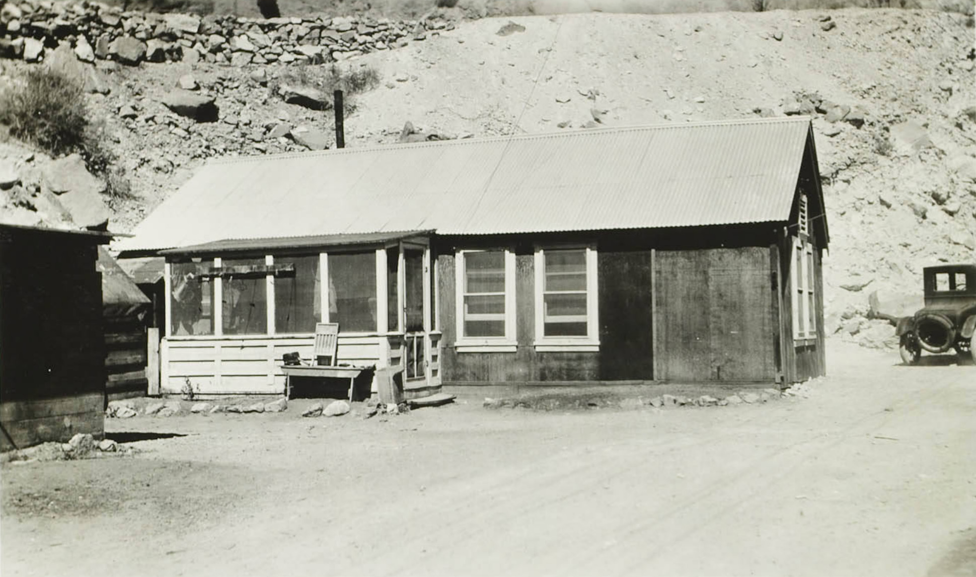
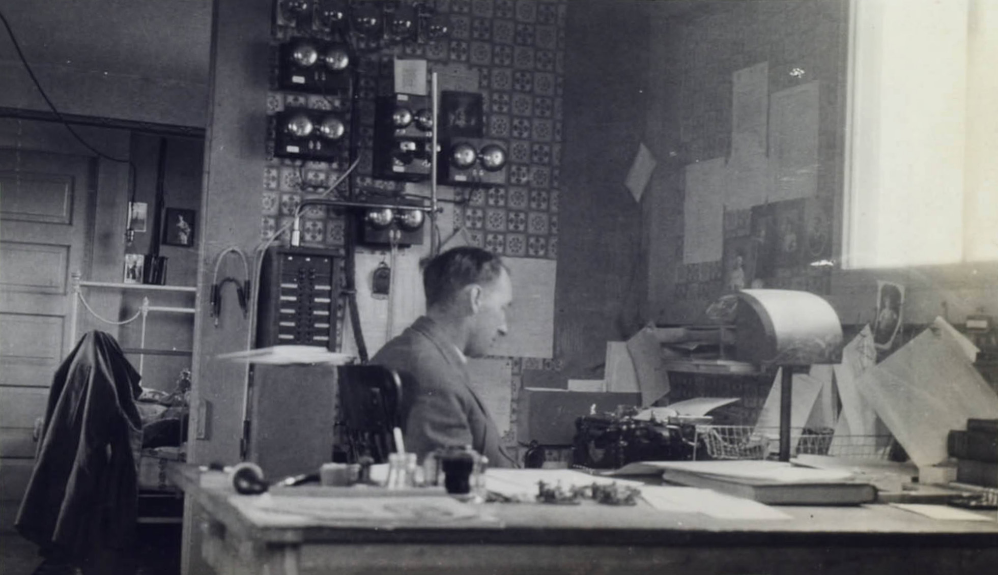
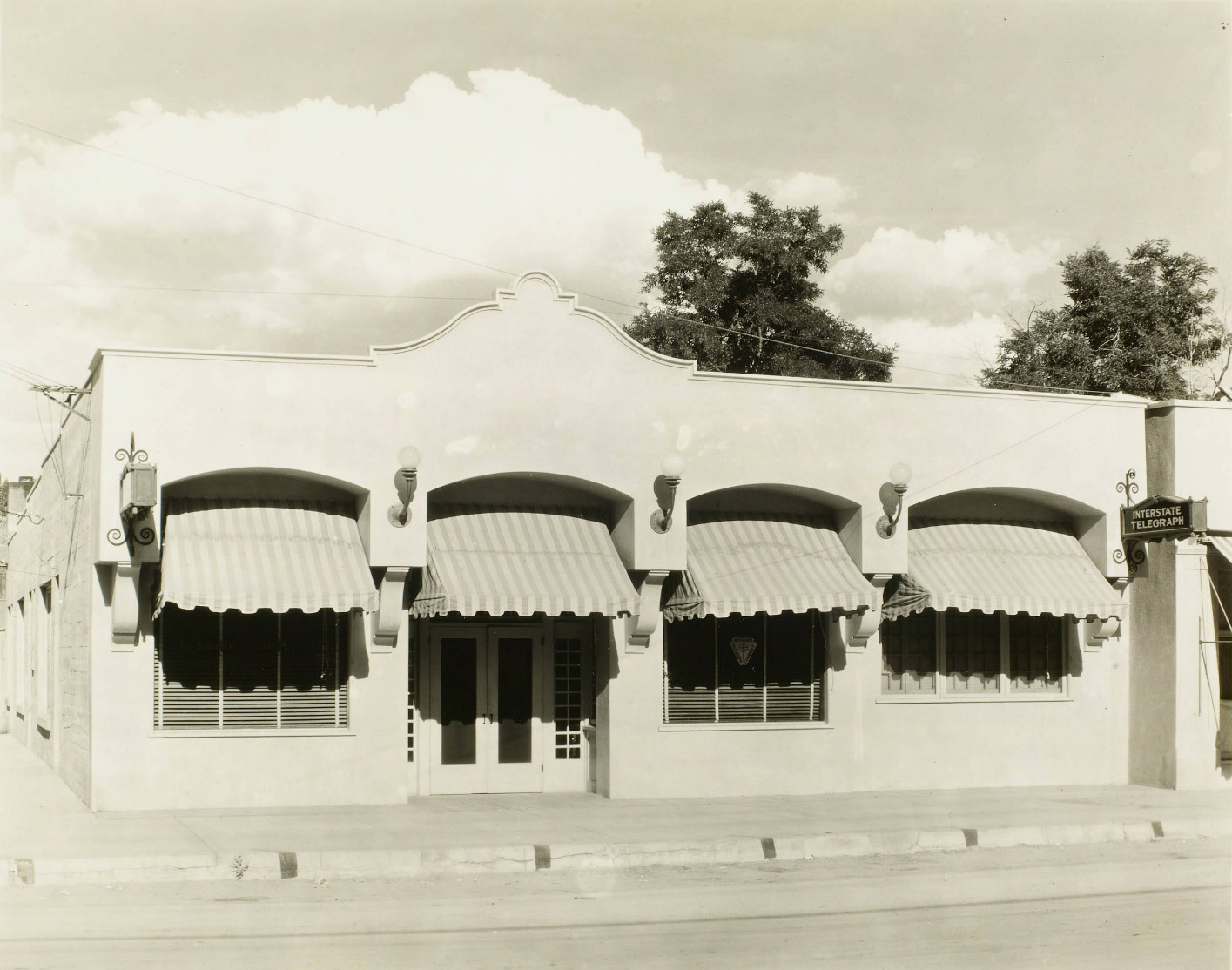 This building houses the main telephone exchange and operating headquarters of the Interstate Telegraph Company and the office of the Local Superintendent of The Southern Sierras Power Company. |
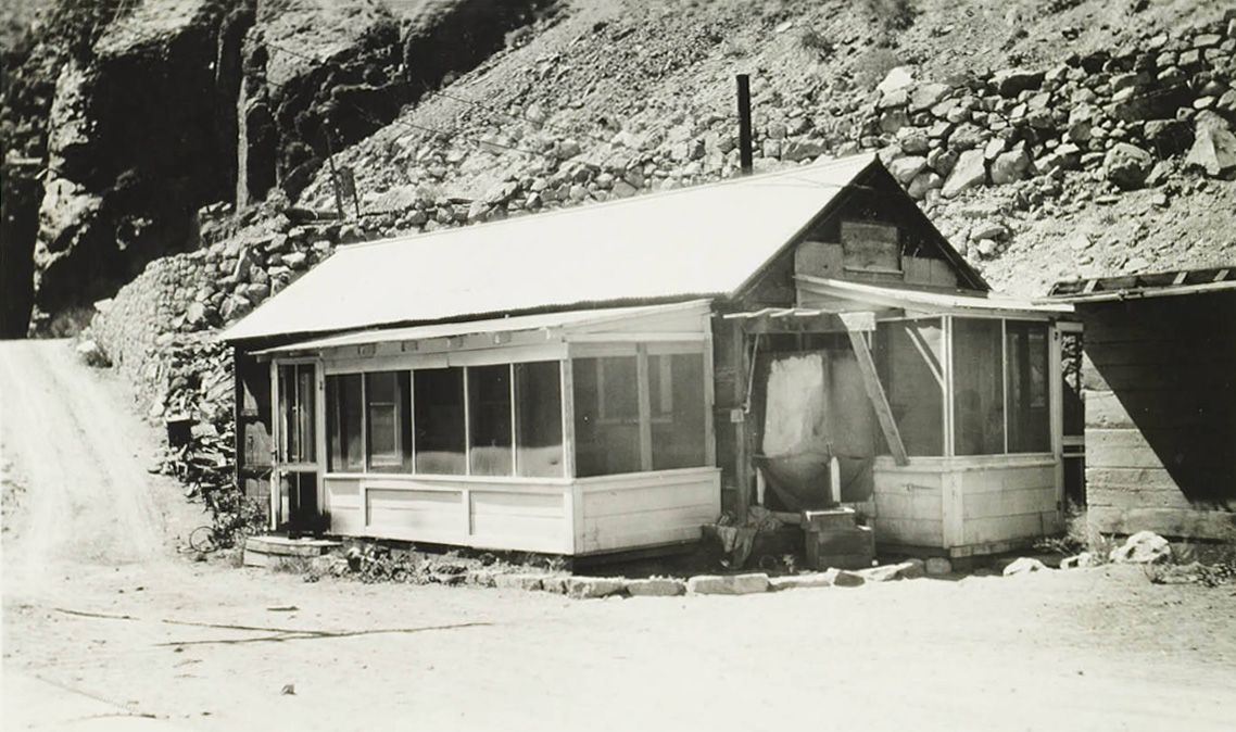 Owens River Gorge dwelling |
 Owens River Gorge dwelling |
 Owens River Gorge - Adams Auxilary - Dwellings and tent house |
 Owens River Gorge - Adams Auxilary - Garage, Dwelling, Tent House |
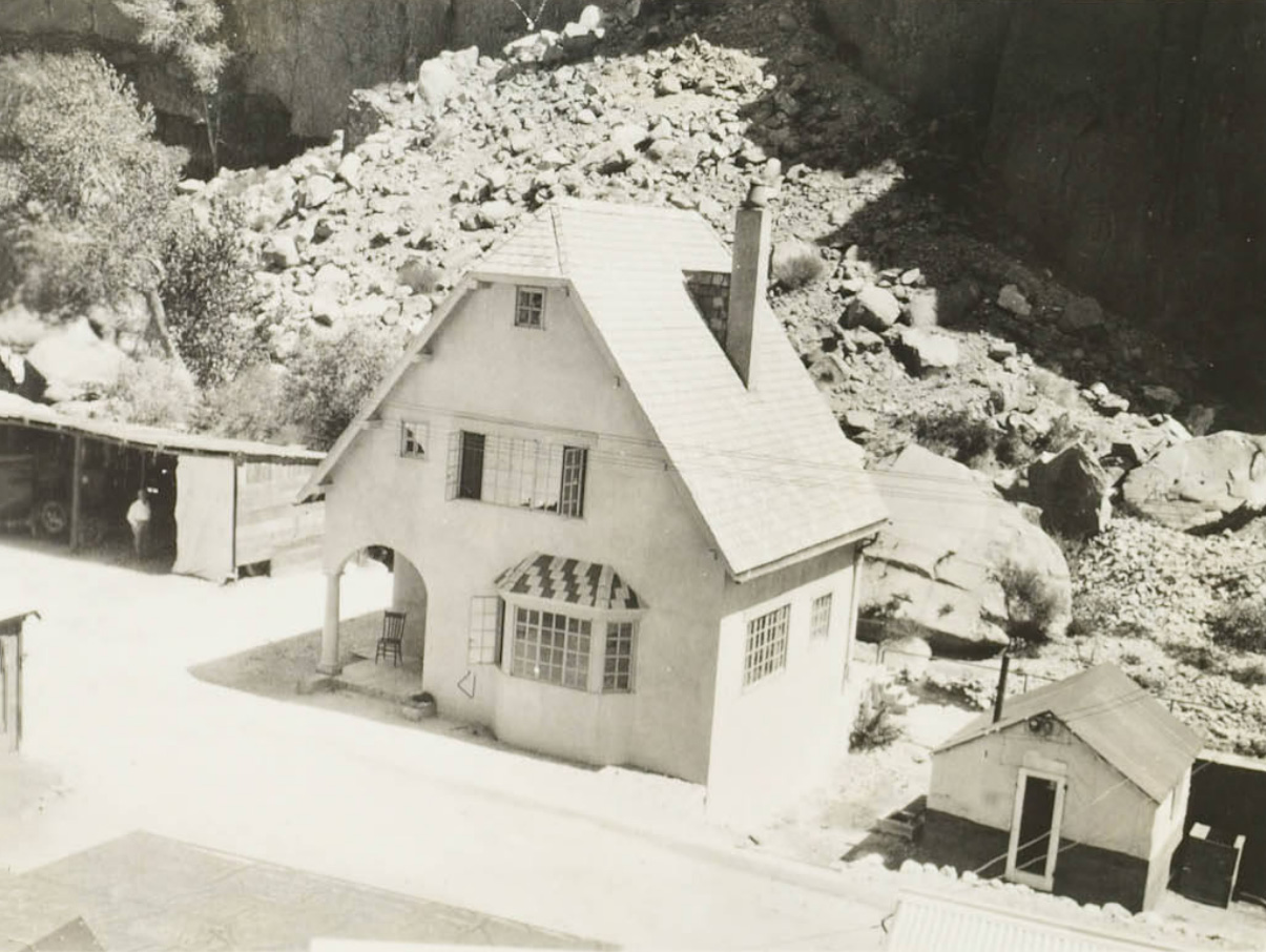
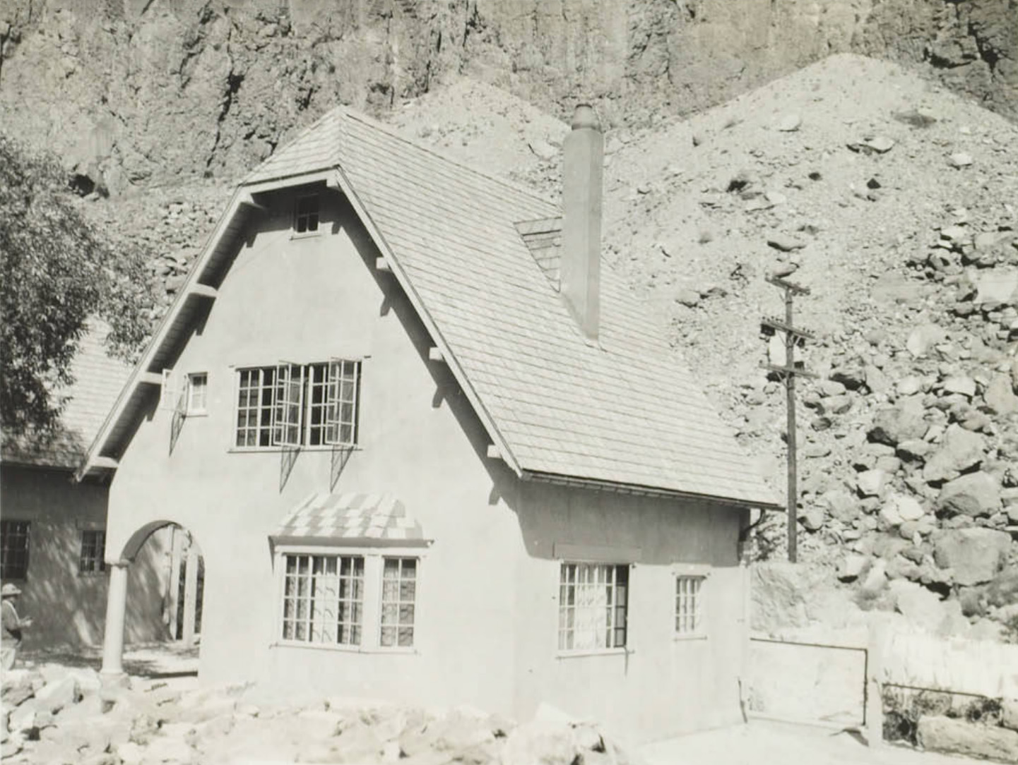 Owens River Main plant dwelling |
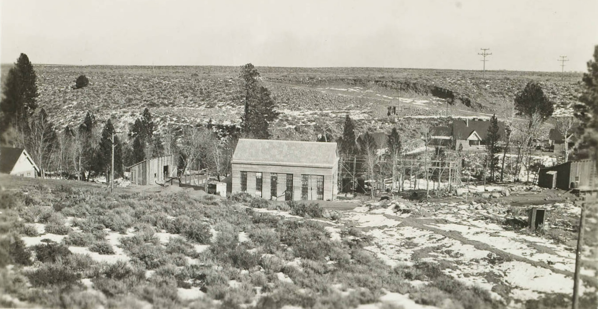
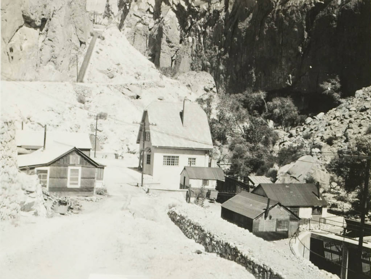
 General view Owens River Gorge |
 Intake cottage Owens River Gorge |
 7.5' diameter pipe for Owens River power plants |
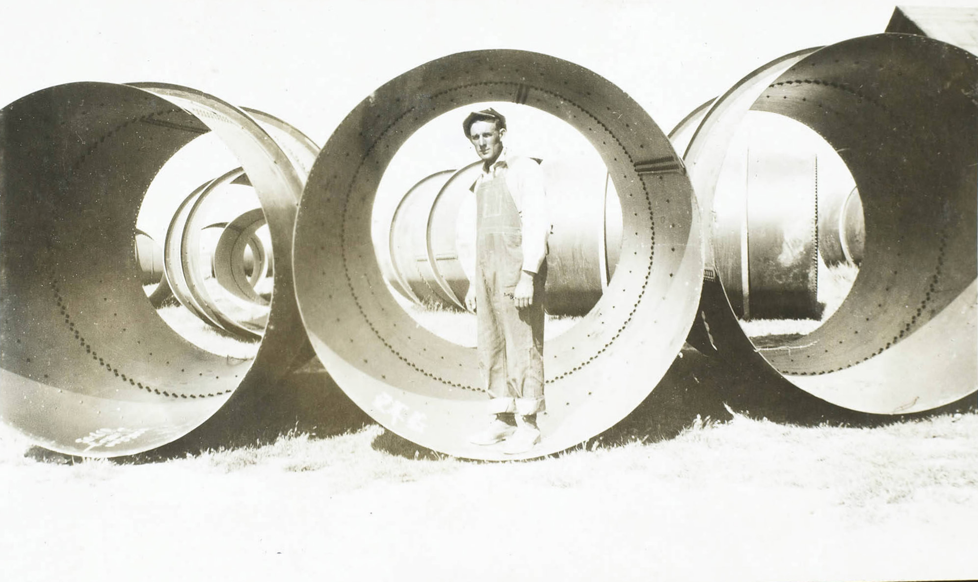 7.5' diameter pipe for Owens River power plants |
Southern Sierra Power Company Supporting Facilities |
|
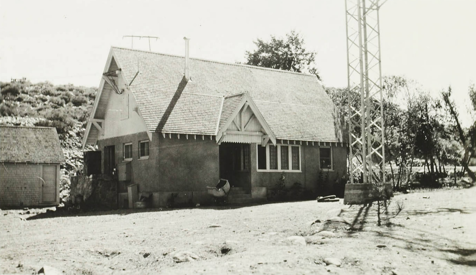
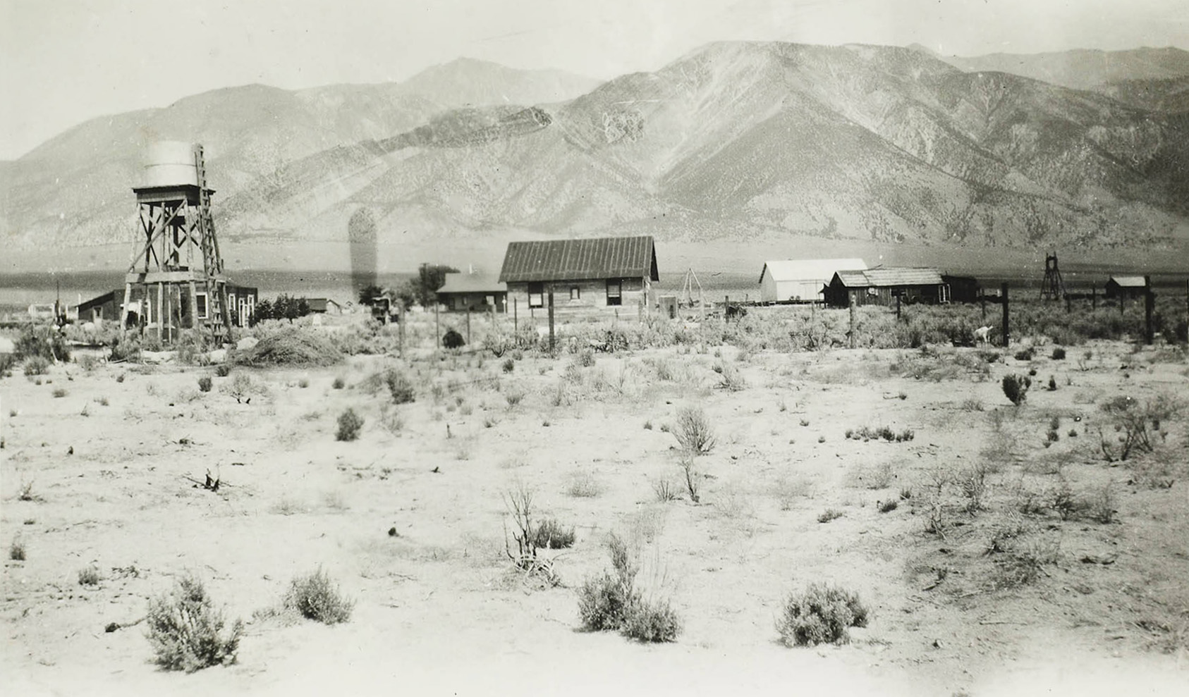
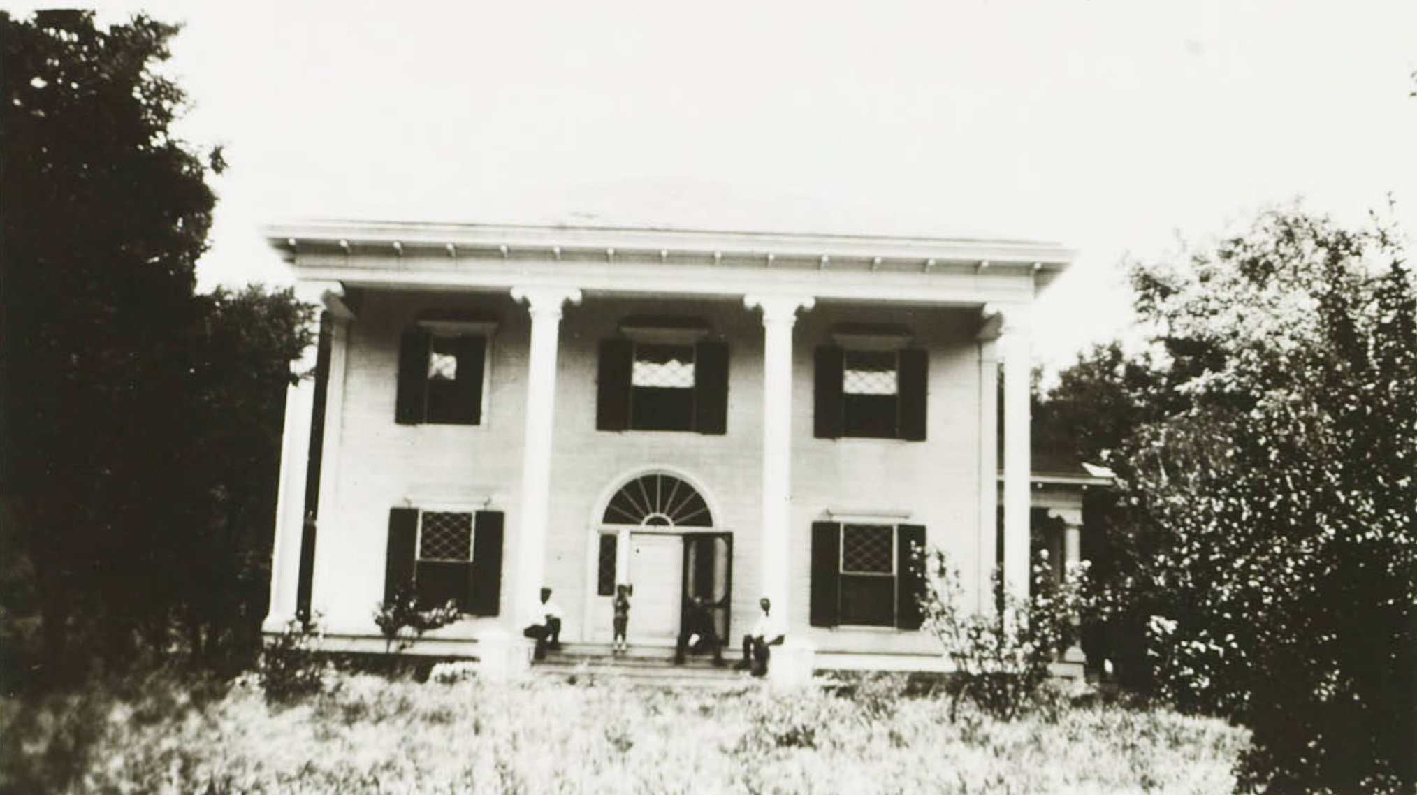
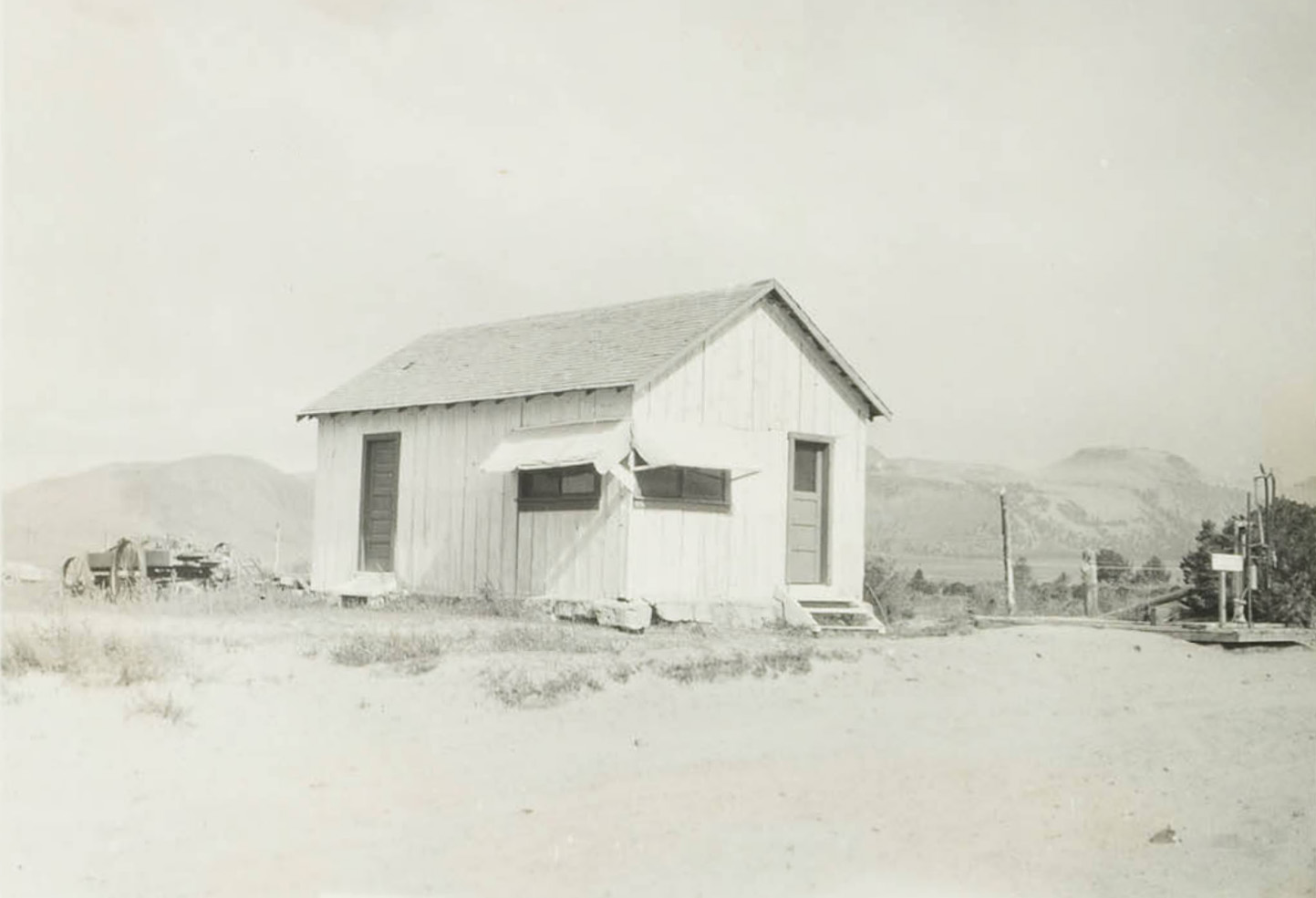
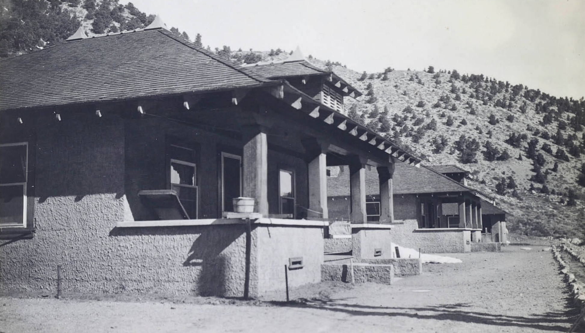
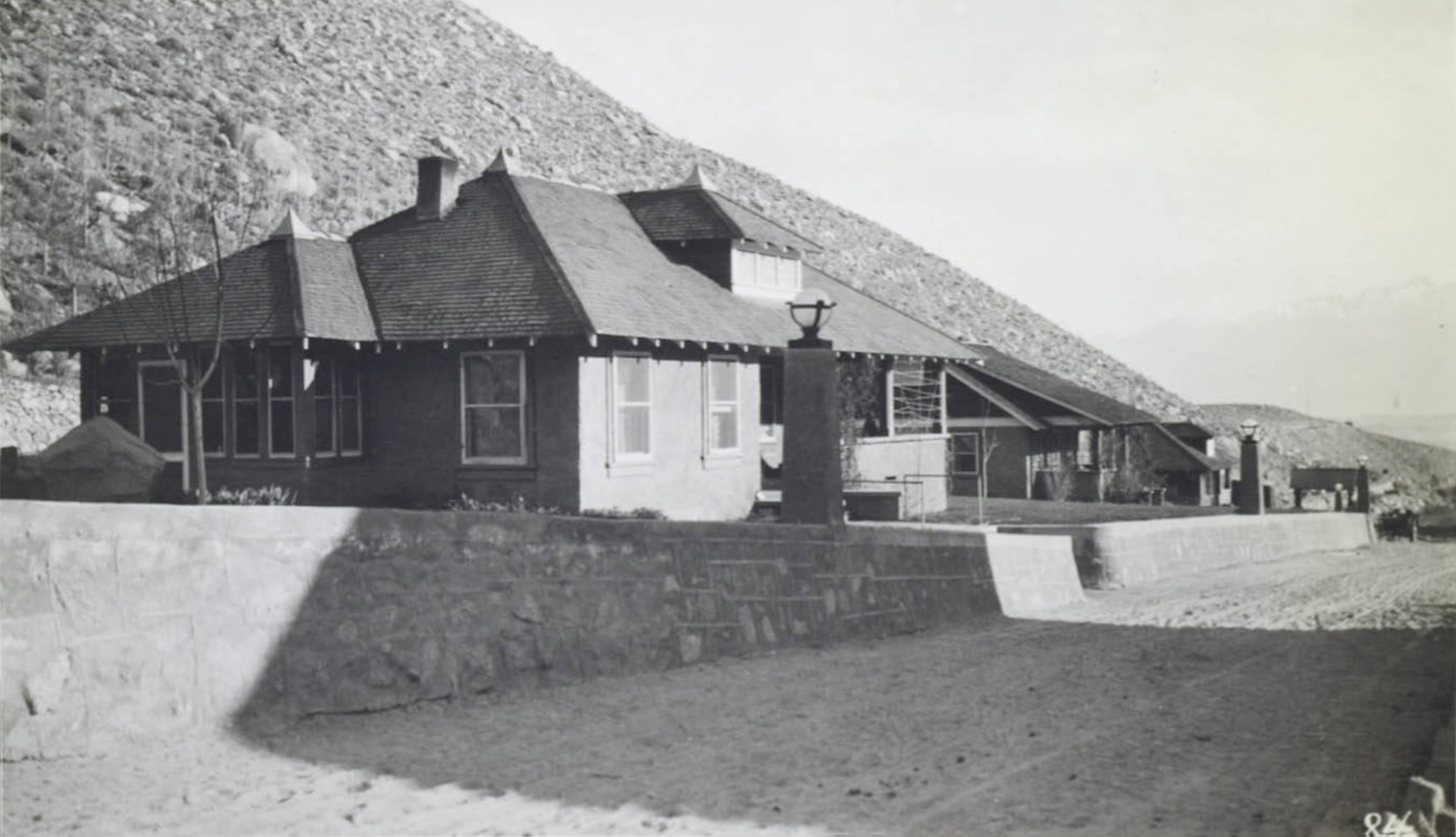
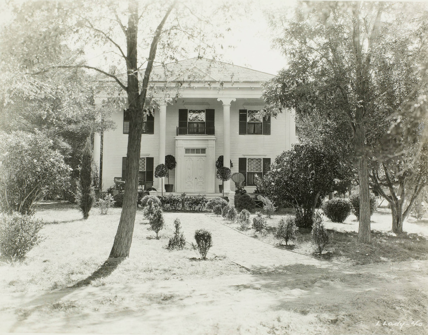 Abelour Ranch house - Hillside Water Company This is the residence of the Ranch Manager and the headquarters of our ranch operations in Inyo and Mono Counties. |
 Abelour Ranch ranch dwelling |
 Abelour Ranch ranch dwelling |
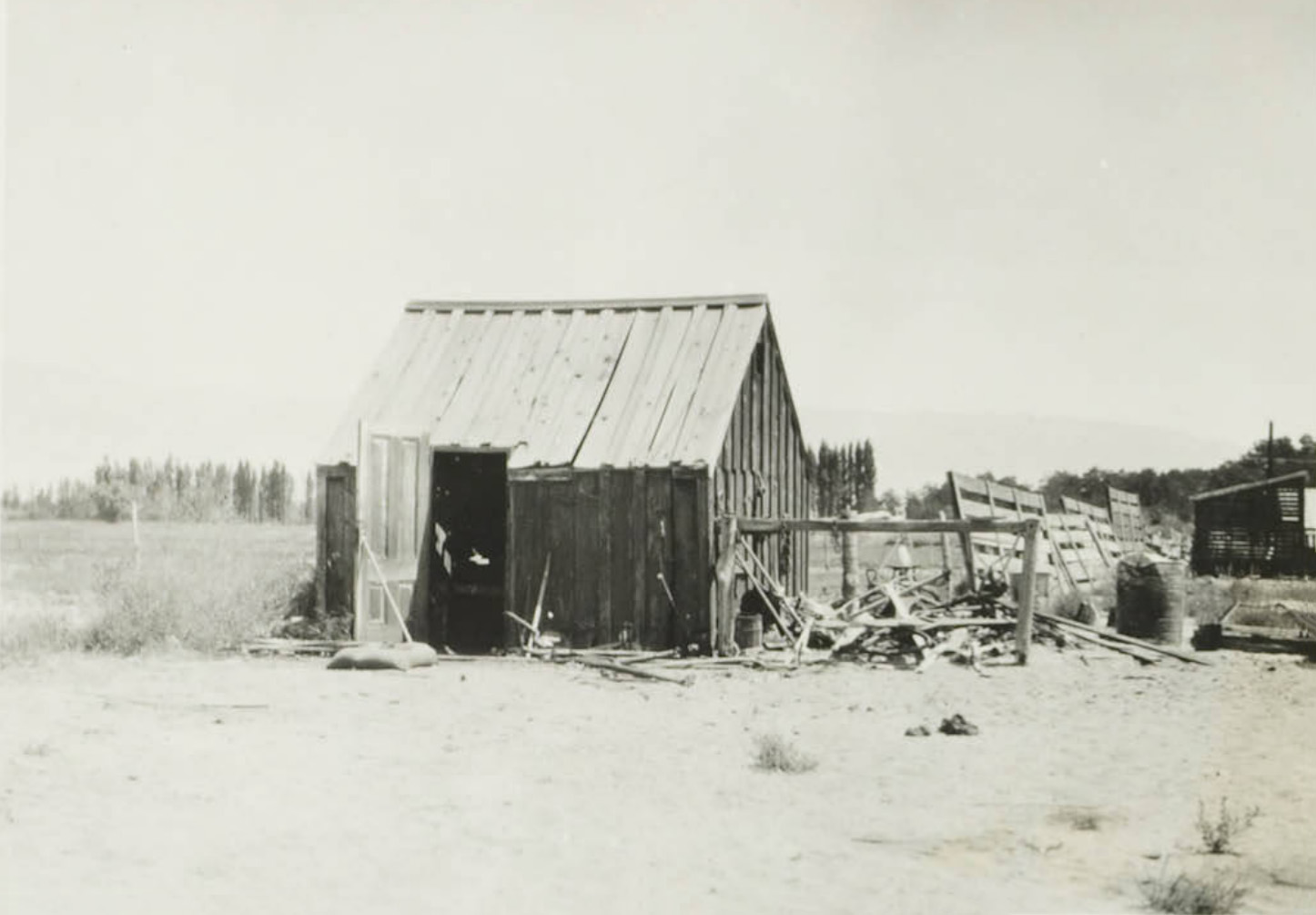
 Abelour Ranch ranch hog shed |
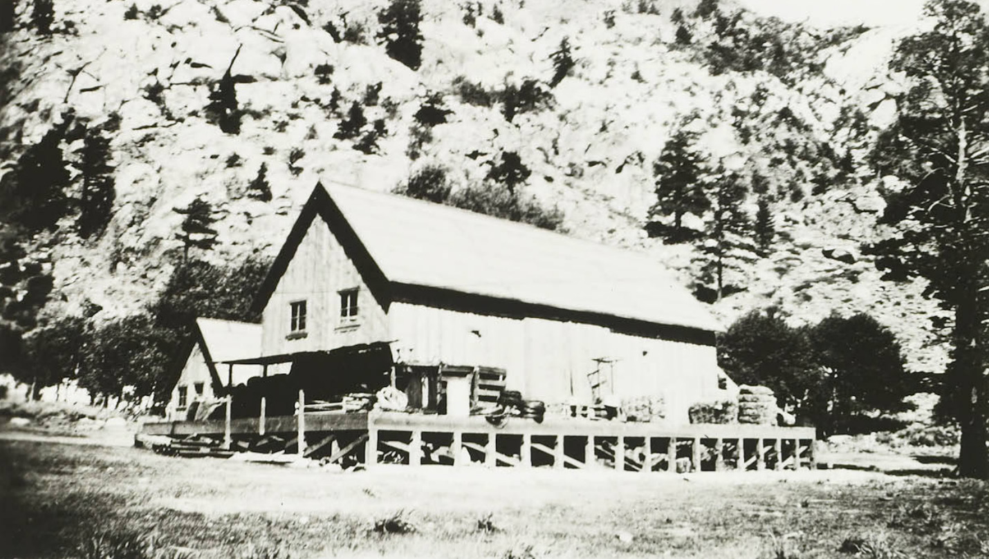
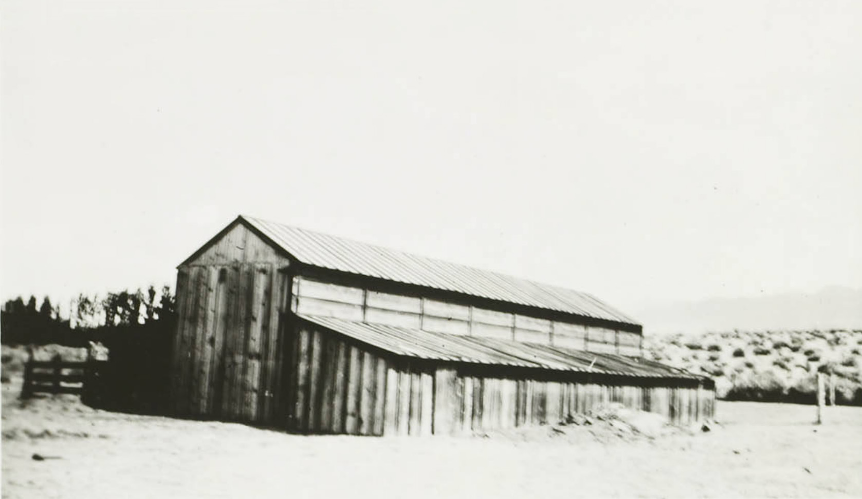
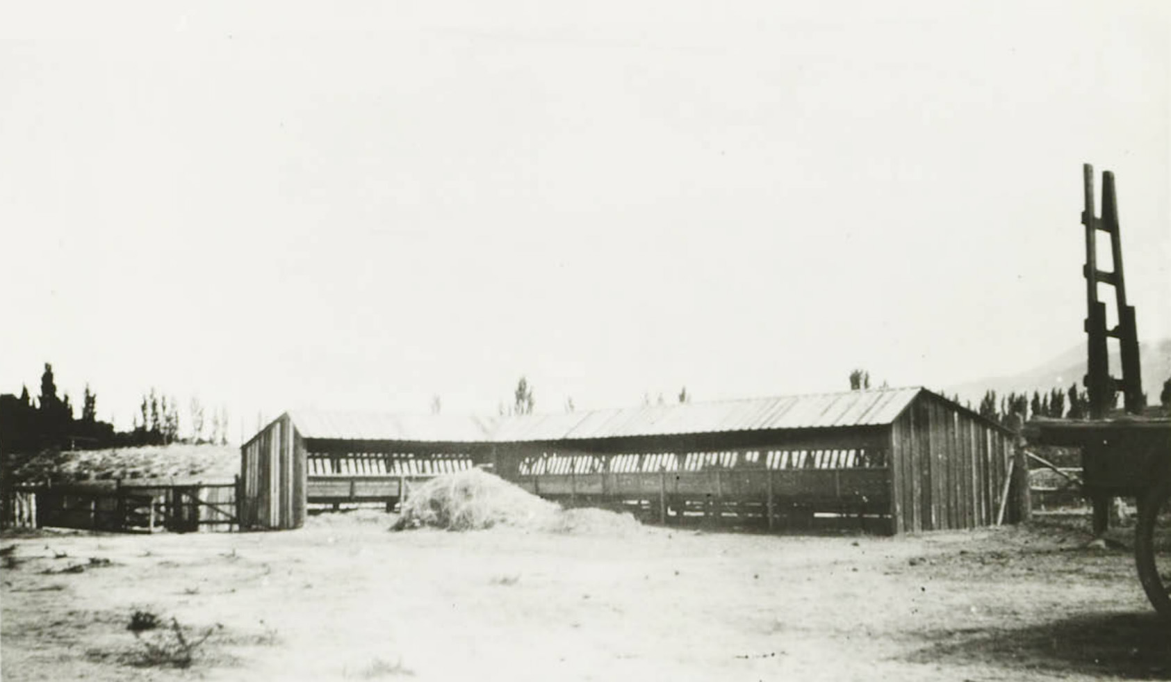 Abelour Ranch ranch feed barn |
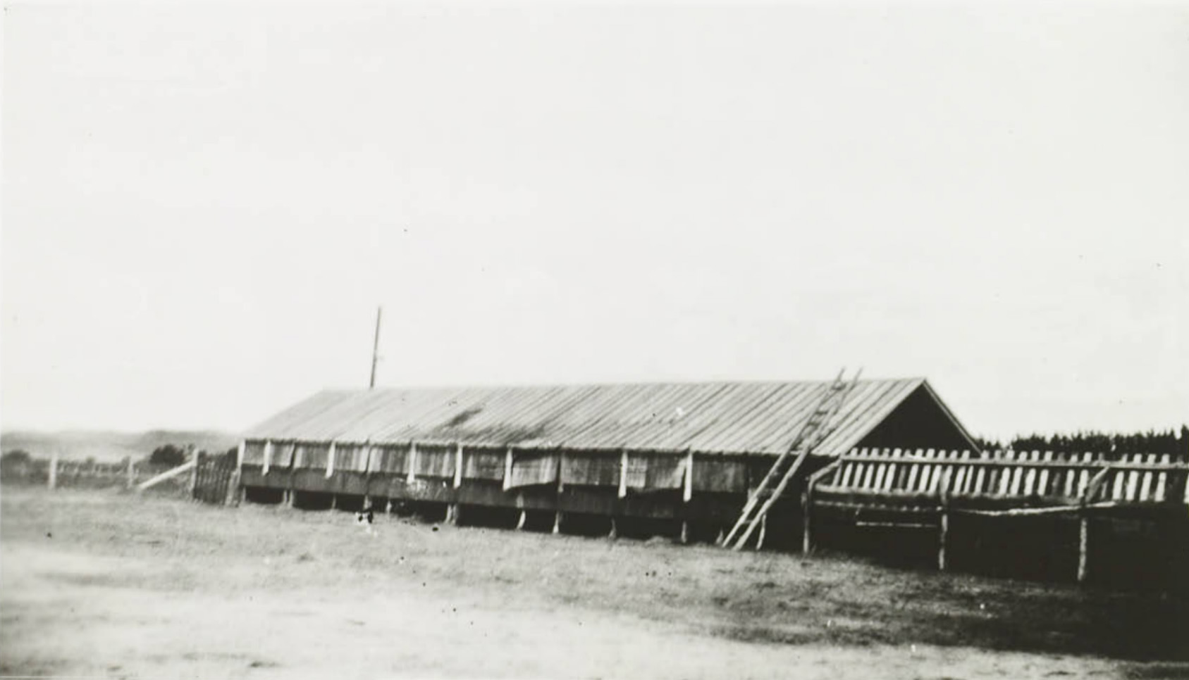 Abelour Ranch ranch stables |
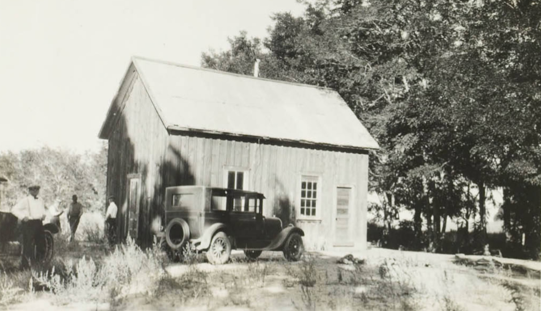
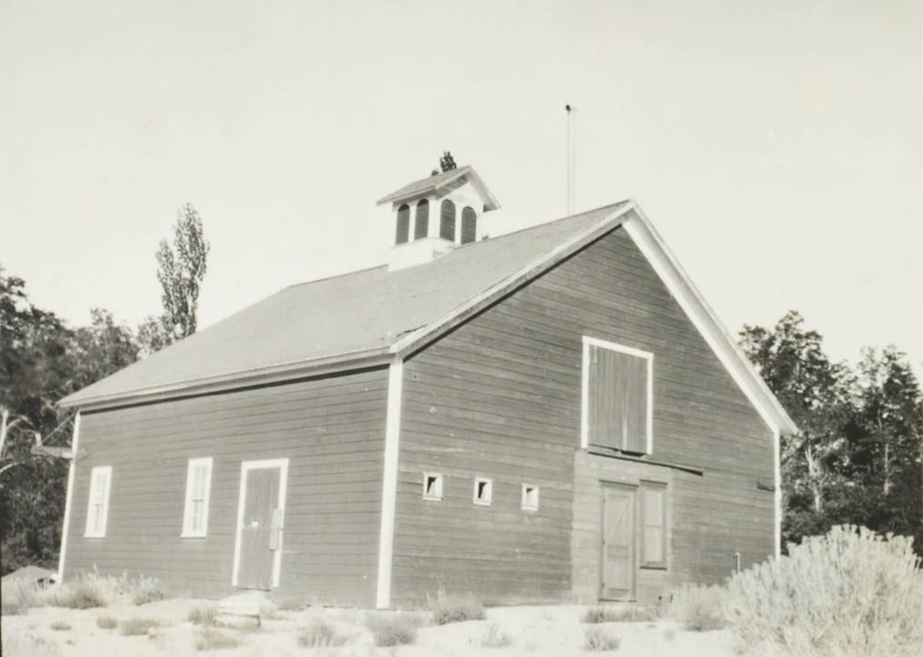
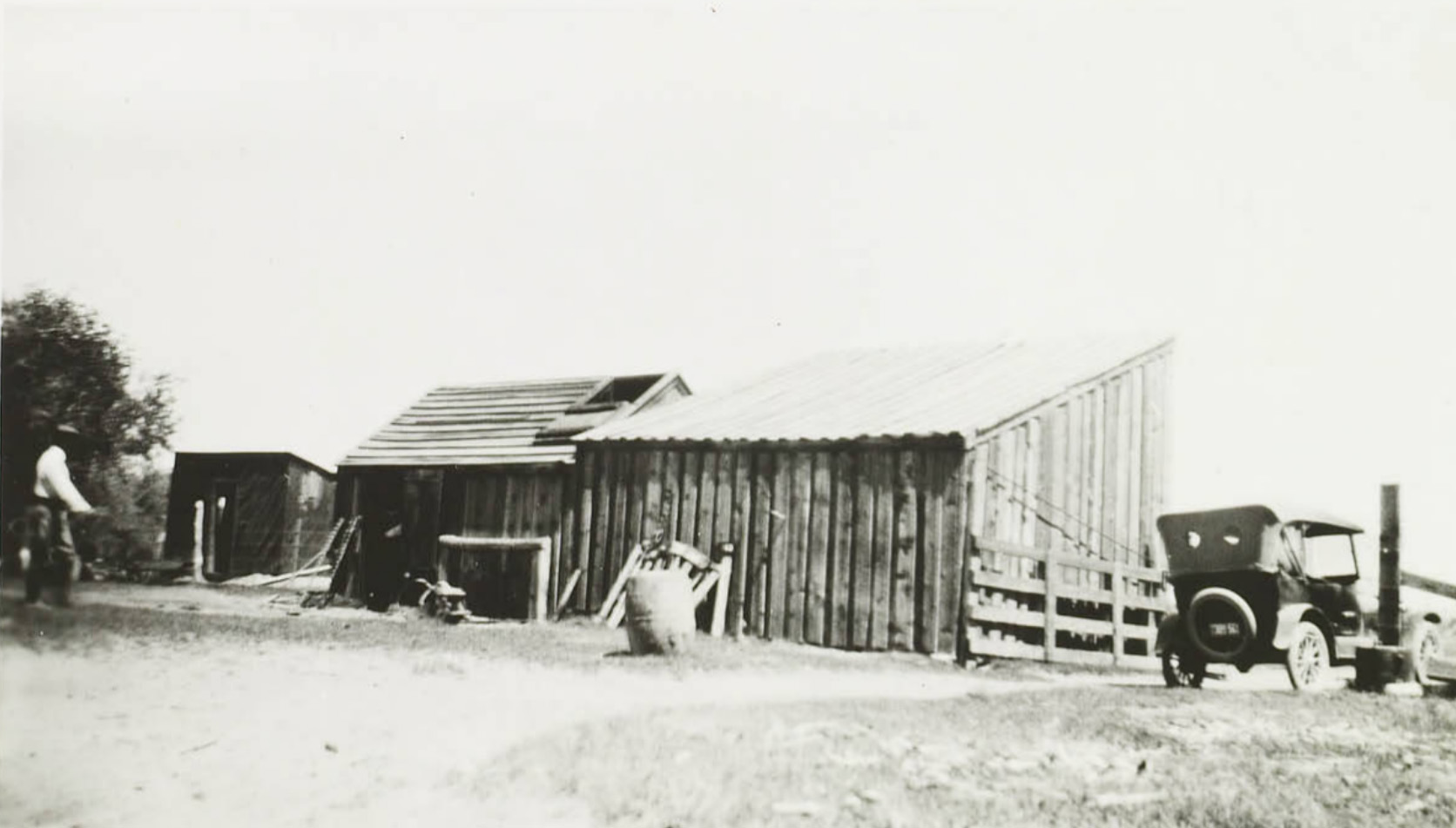
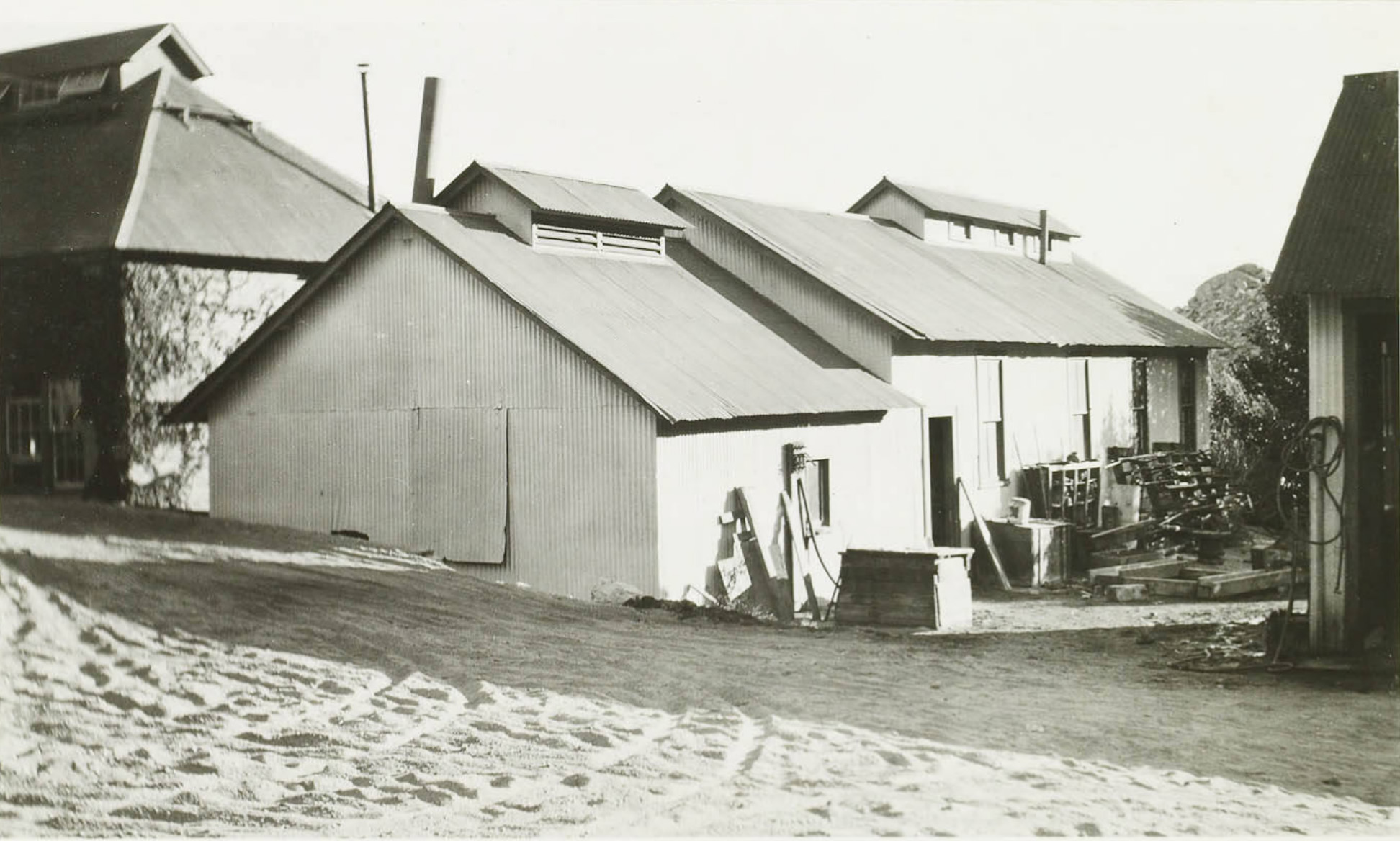
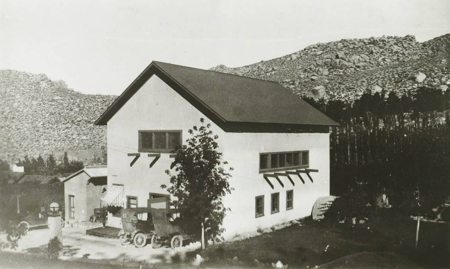
 Abelour Ranch ranch repair shop |
 Abelour Ranch ranch bunk house |
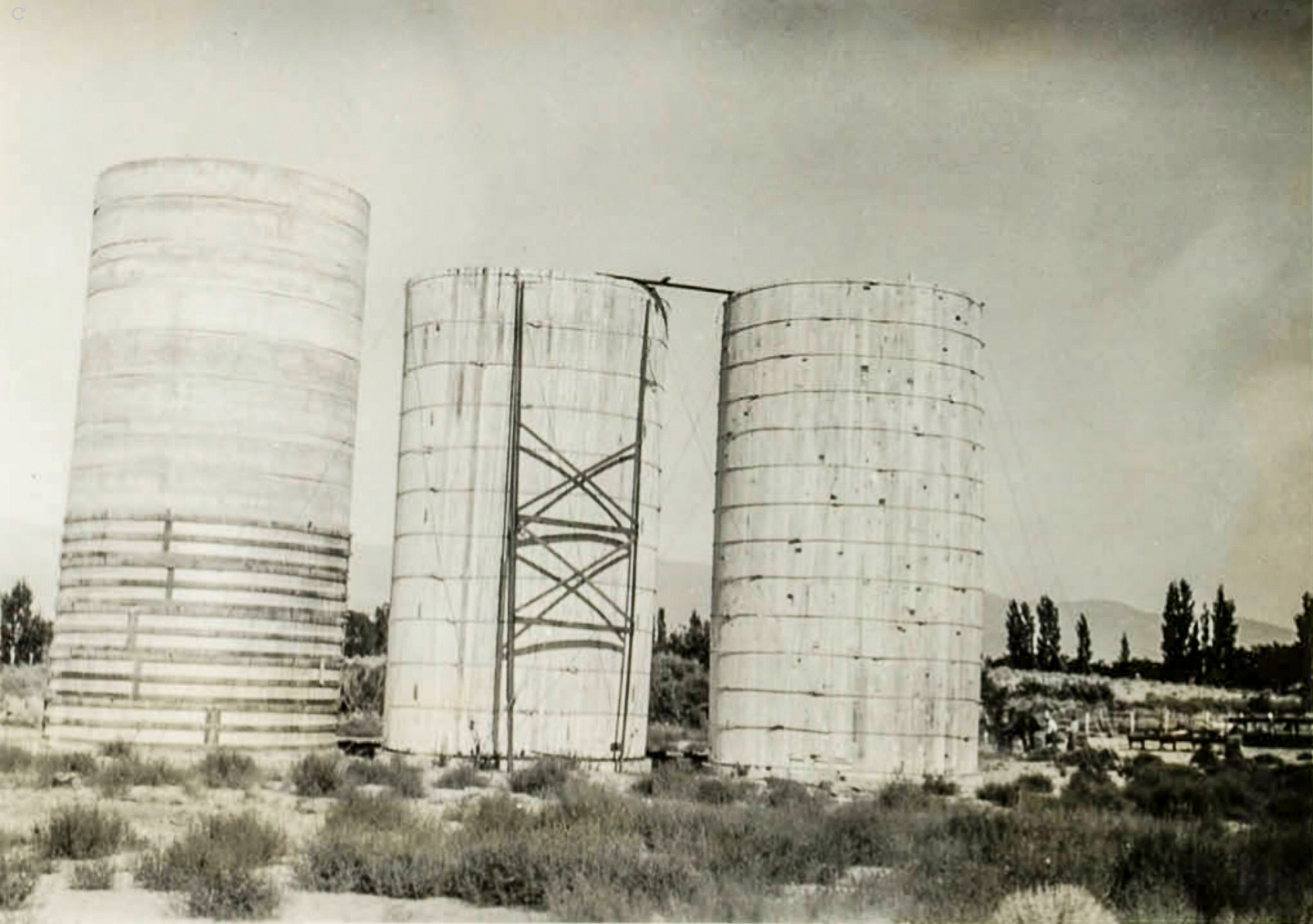 Abelour Ranch ranch repair grain silos |
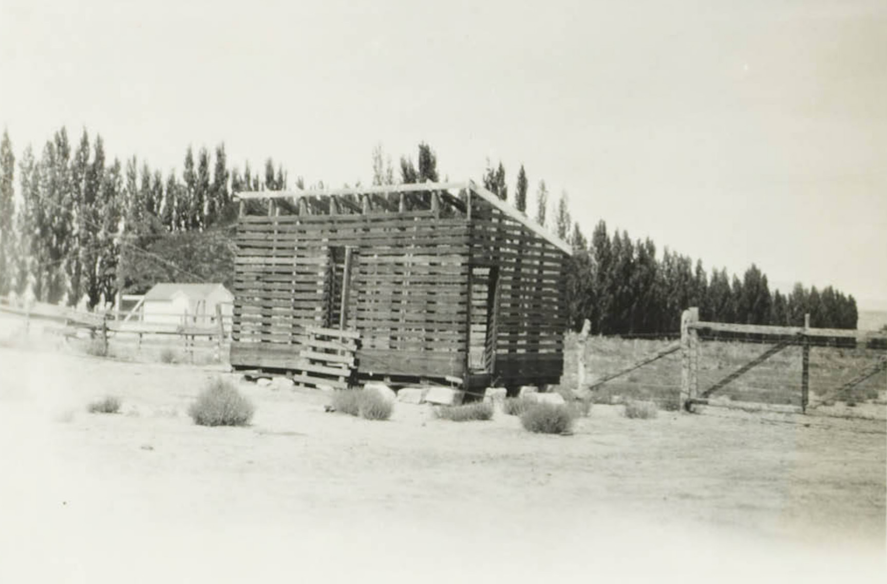 Abelour Ranch ranch corn crib |
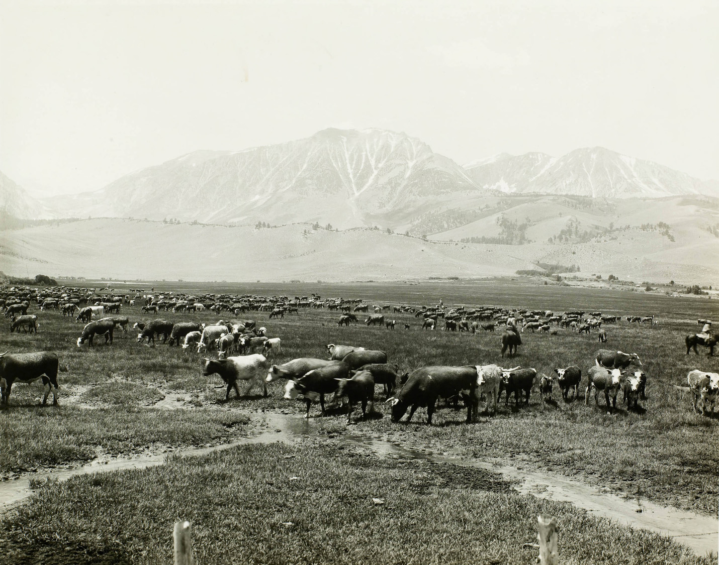 Cain Ranch - Cain Irrigation Company Beef cattle on summer range on the Cain Ranch. Over 1000 head of cattle are in the herd shown in this photograph. The ranch is irrigated with water impounded at Grant Lake Reservoir, below the Rush Creek Power Plant. |
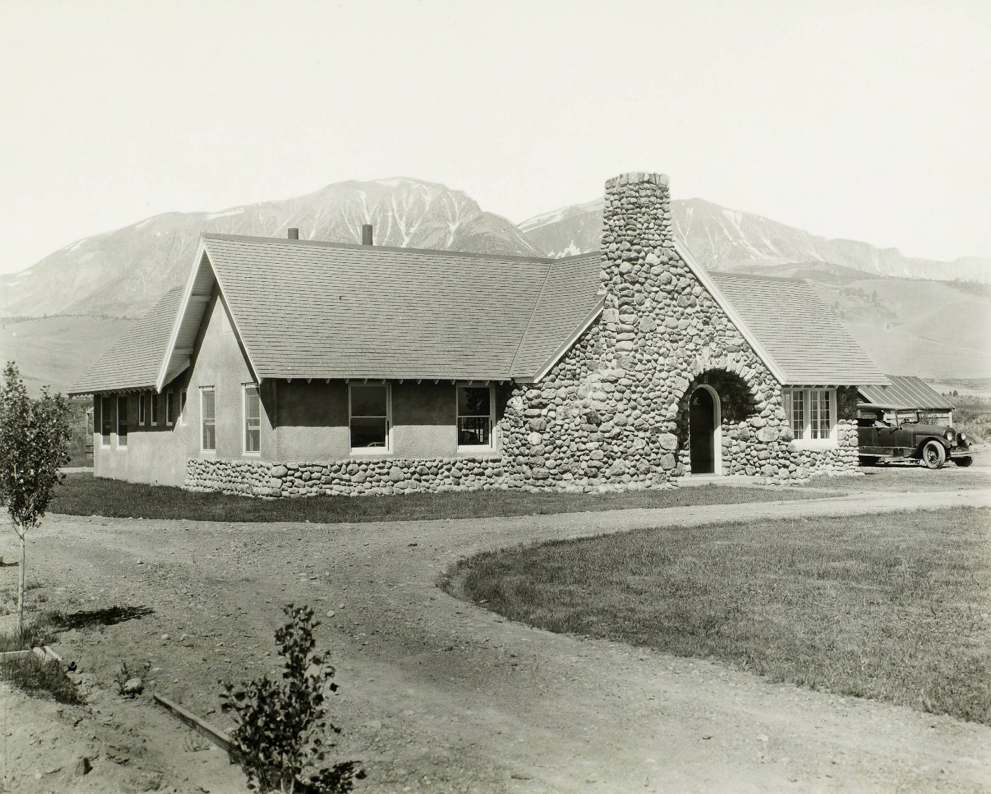 Cain Ranch clubhouse and ranch headquarters |
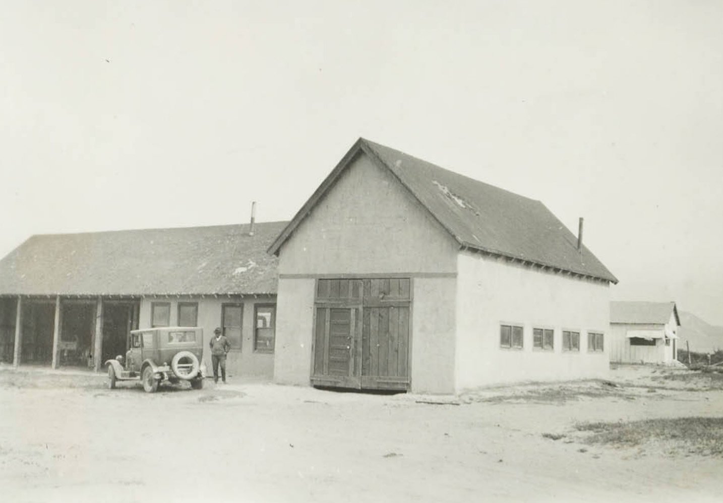
 Cain Ranch private garage |
 Cain Ranch storage building |
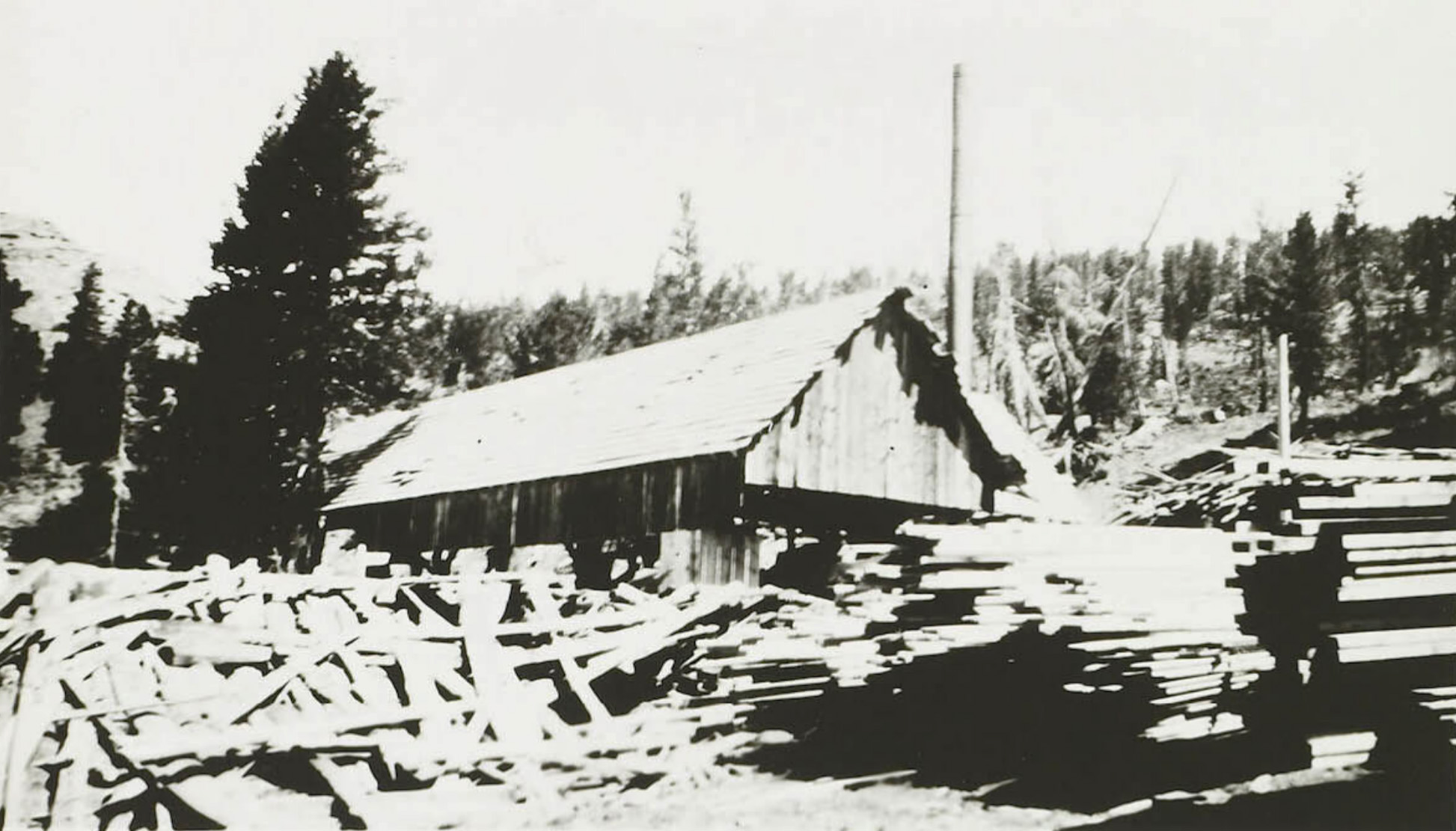 Cain Ranch sawmill |
 Cain Ranch implement shed |
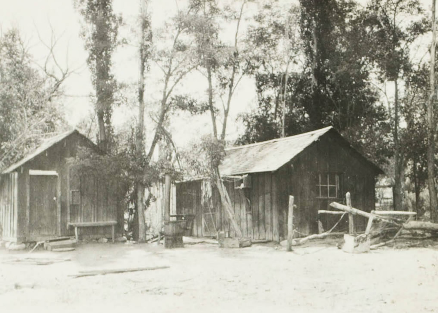 Red Hill Ranch dwelling |
 Red Hill Ranch Granery |
 Red Hill Ranch dwelling |
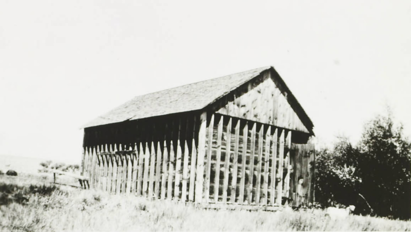 Turner Ranch Granery |
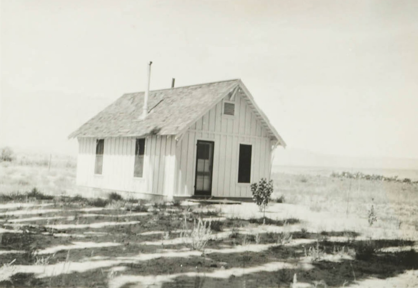
 Turner Ranch Dwelling |
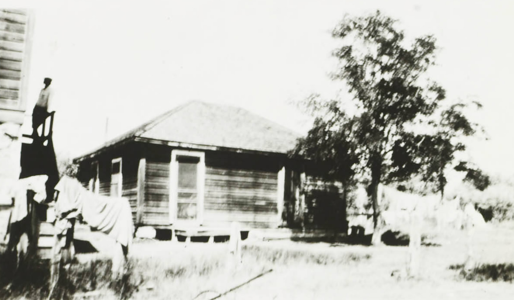
 South Hillside Ranch Dwelling |
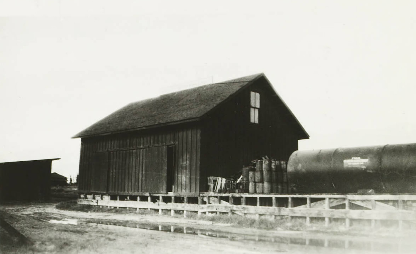 Warehouse at the SPNG depot at Laws, CA |
|
 Warehouse at the SPNG depot at Laws, CA |
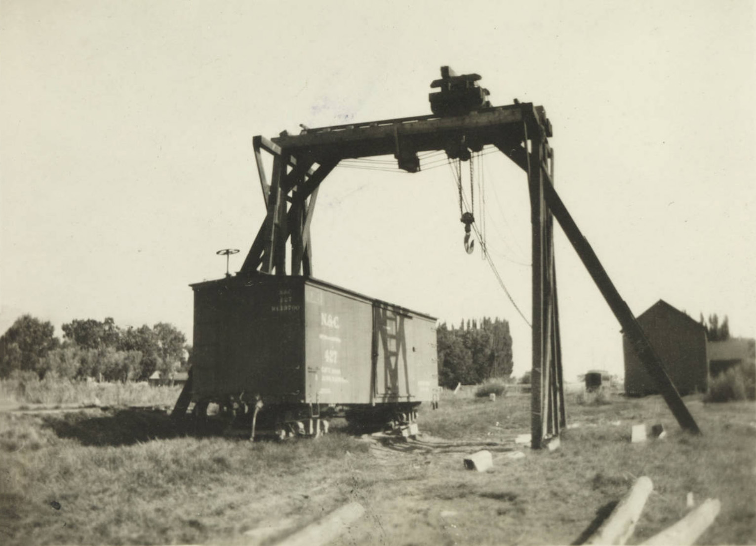 SPNG gantry at Benton, CA |
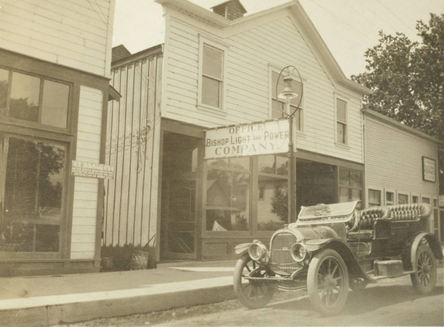 Bishop, CA office |
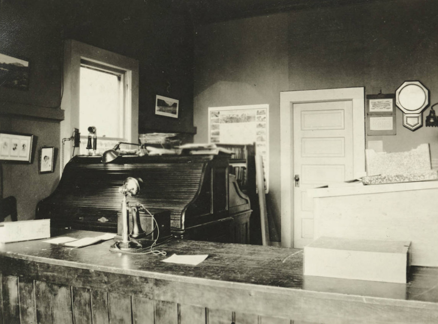 Bishop, CA office interior |
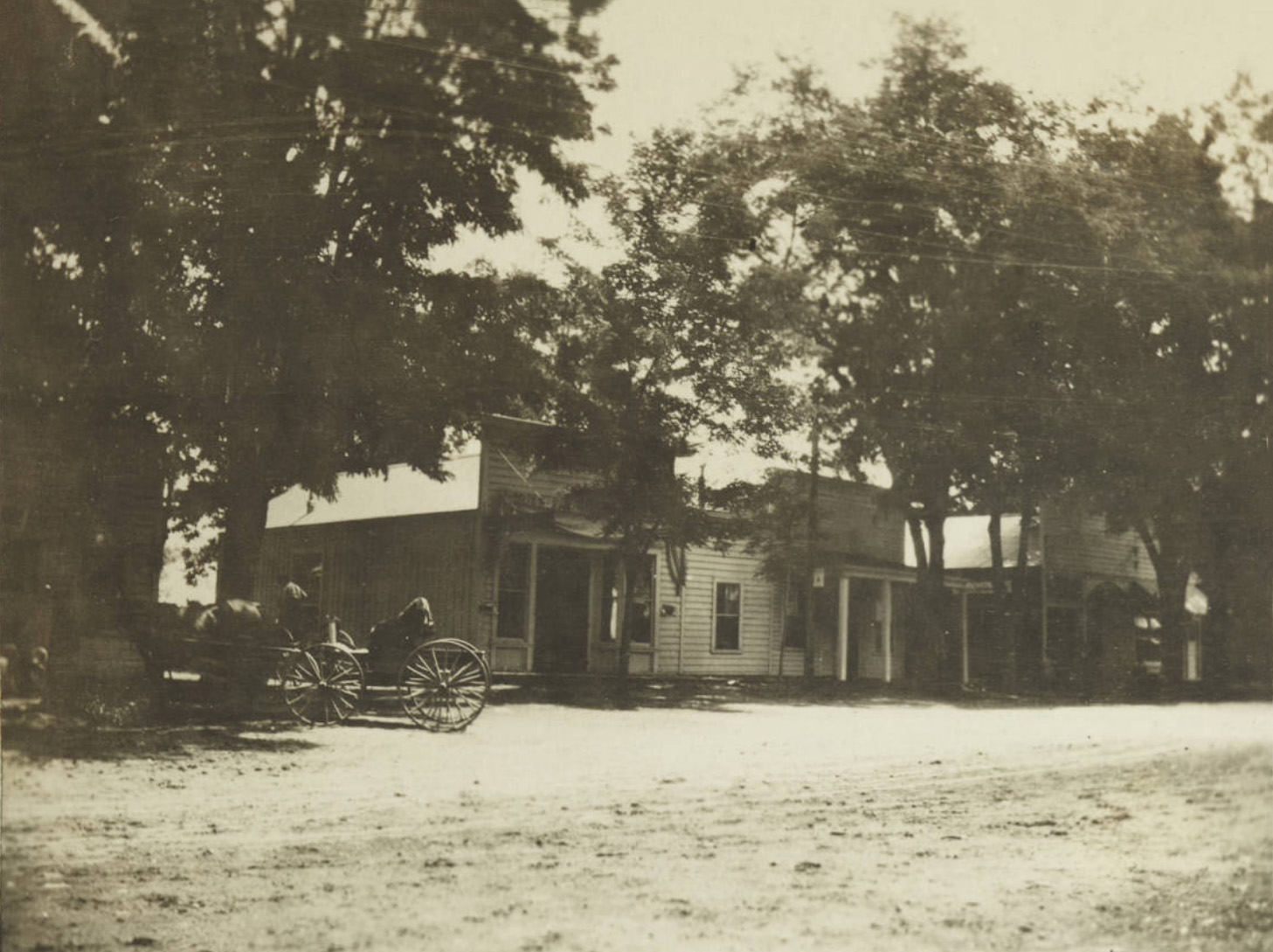 Big Pine, CA office |
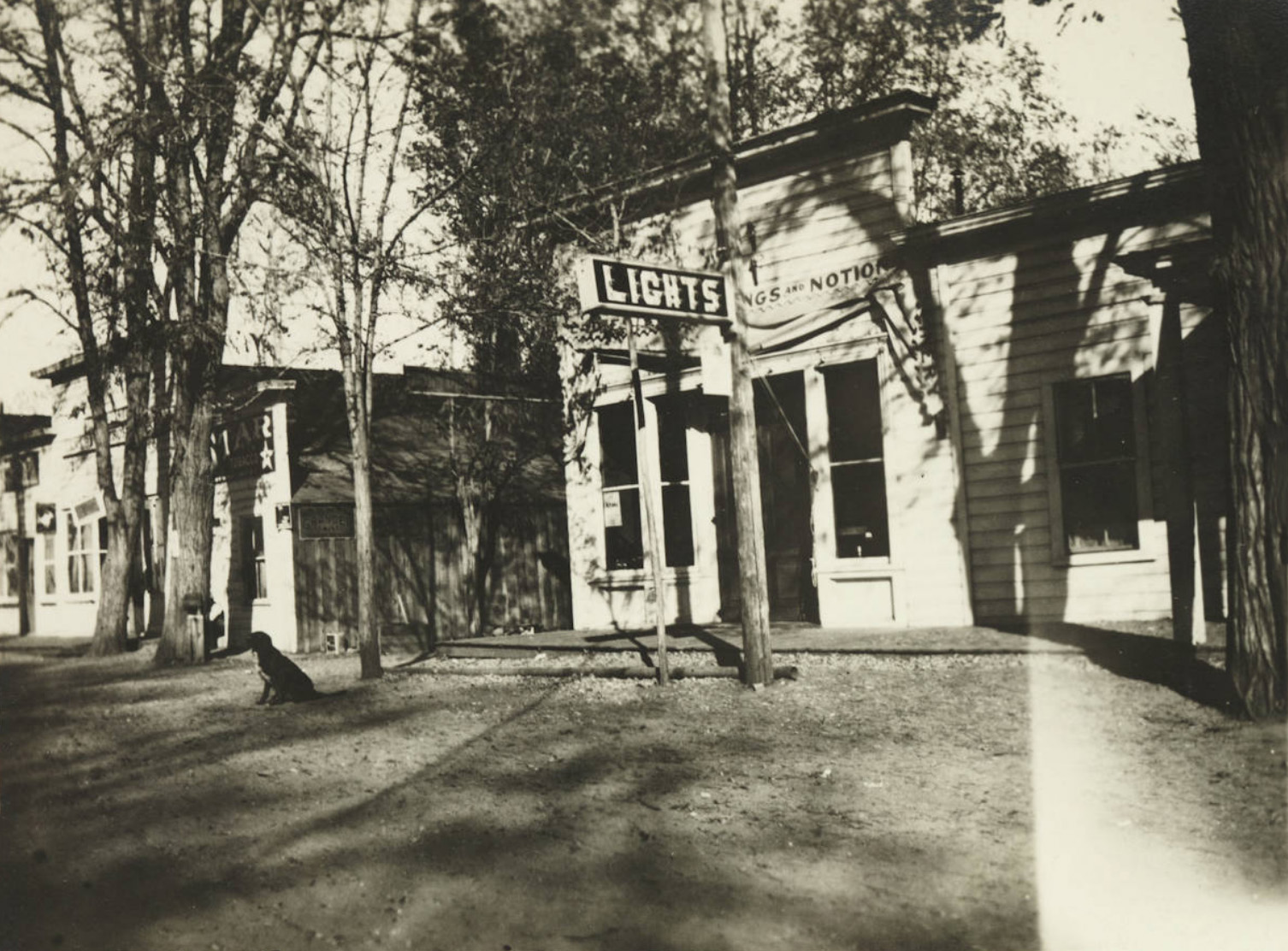 Big Pine, CA office |
 Independence telephone exchange |
 Bishop Switch House |
 Big Pine automitic telephone exchange |
 Independence office |
 Lone Pine telegraph office |
 Storage warehouse in Lone Pine |
 Warehouse on the SP at Lone Pine, CA |
 Warehouse on the SP at Lone Pine, CA |
 Bishop Creek warehouse |
 Warehouse at Benton, CA |
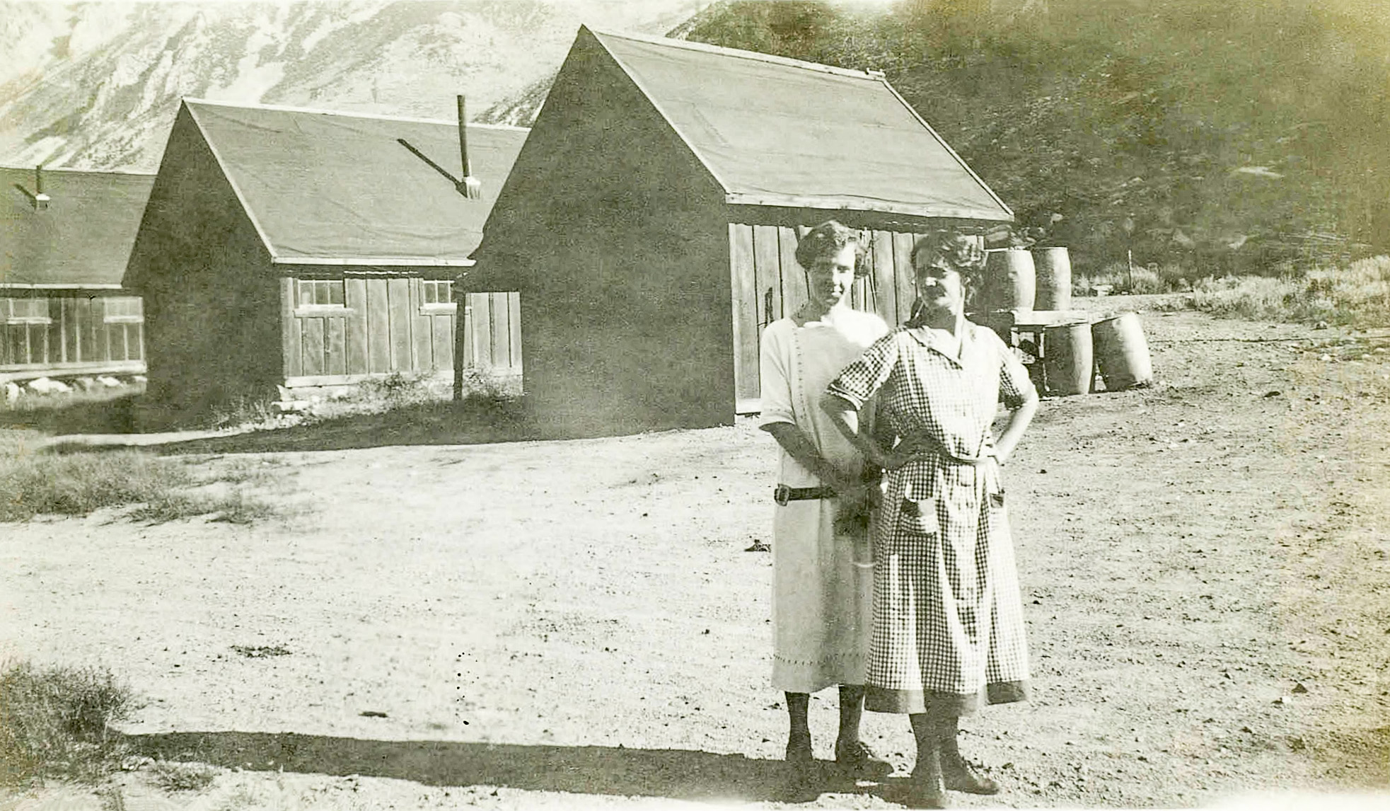 Wifes supporting their husbands in one of the construction camps |
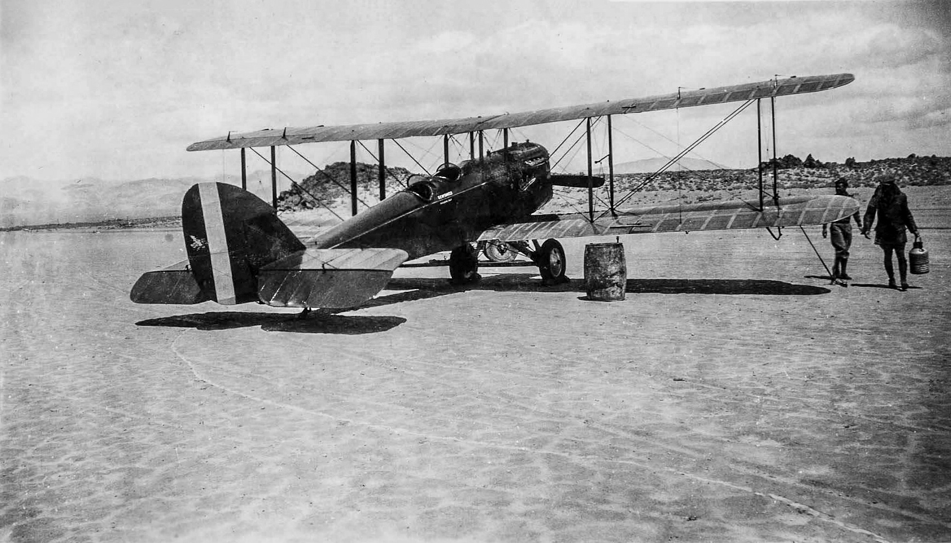
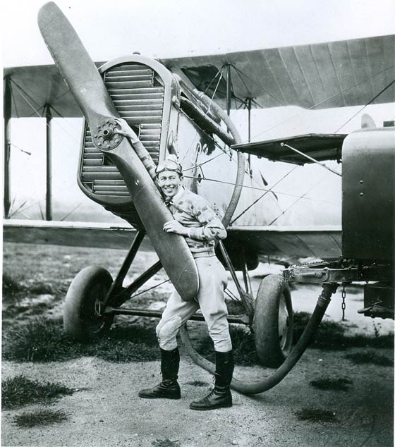
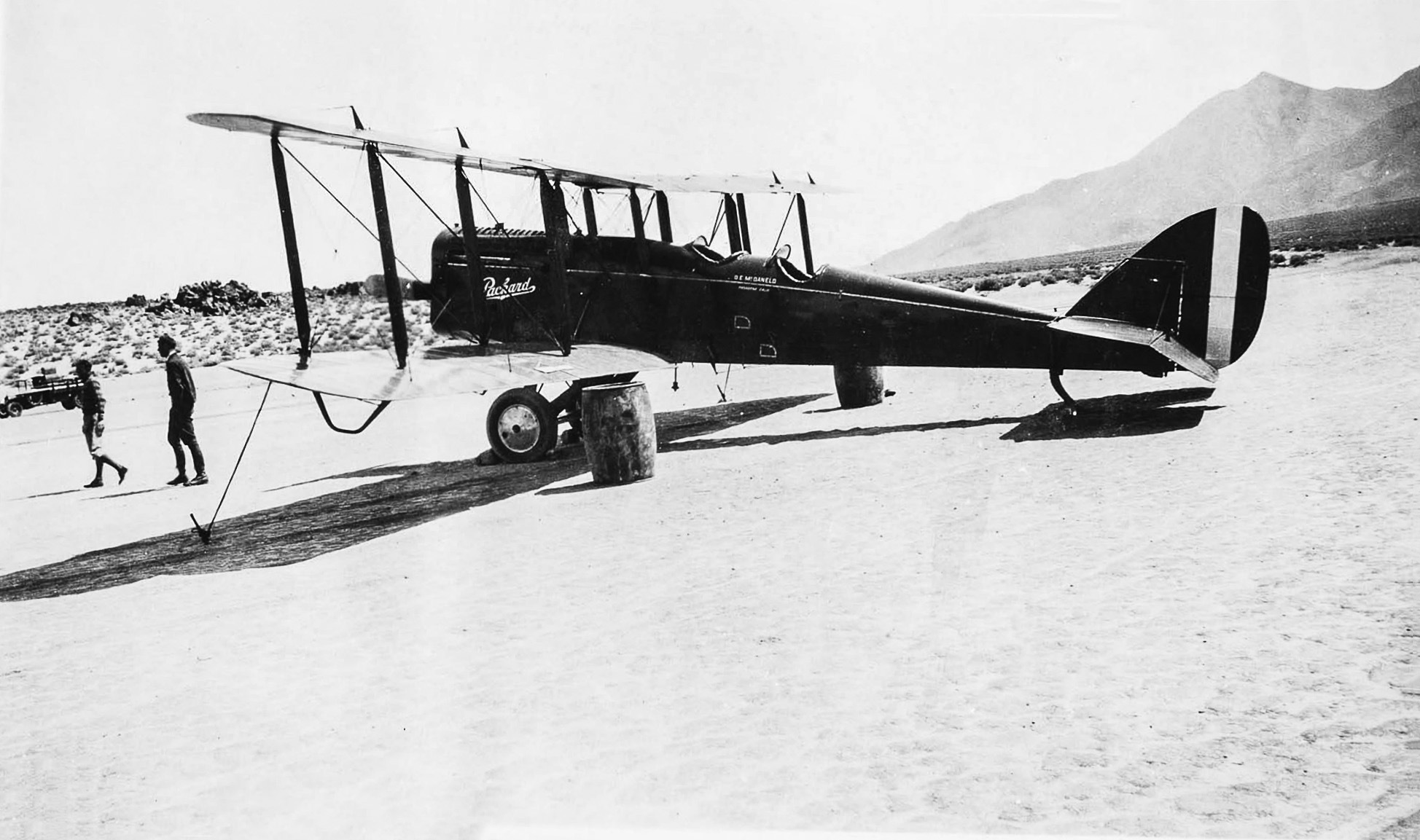 Packard Bi-Plane The owner and pilot was D. E. McDaneld of Pasadena who was a Packard dealer and early Pacific Coast pilot. The other owner of NC298 Curtiss JN-6H was Boyd Monteith Shelton. In 1927 they had a firm based out of Arcadia that did Fairchild Aerial Mapping surveys. Shelton was primary pilot. (Hal Eaton) McDaneld & Shelton also took aerial shots and ferried materials for motion pictures. Boyd also was a pilot in Al Wilson's stunt crew in "The Cloud Riders" in 1925. (Hal Eaton) |
 Packard Bi-Plane |
|
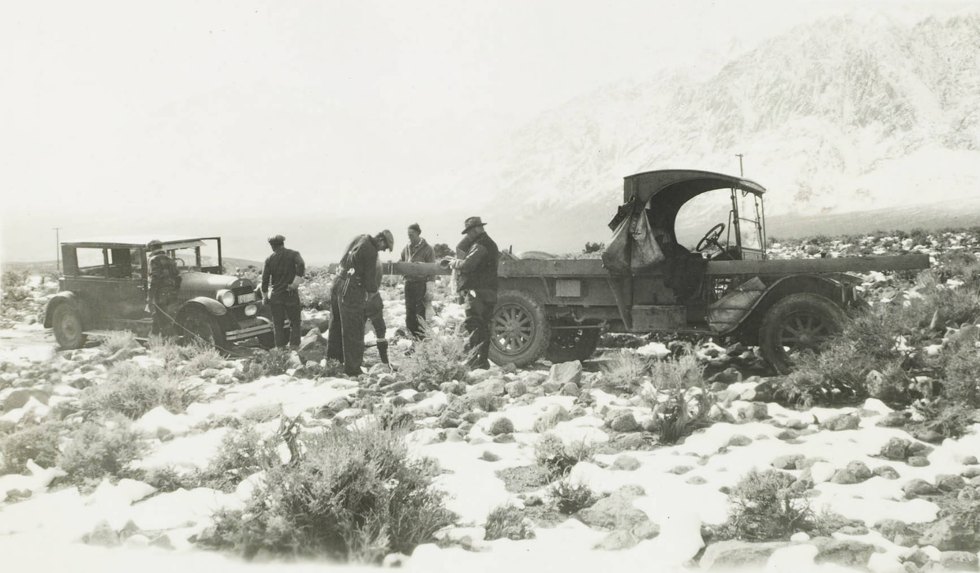
Transporting Equipment & Materials to Powerhouses |
|
 Plant equipment arriving by rail on the SPNG at Laws |
 Hauling a piece of equipment to one Bishop Creek Plants by wagon |
 Plant equipment arriving by rail on the SPNG at Laws |
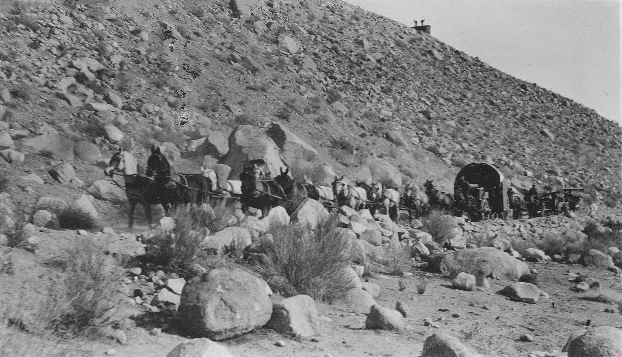
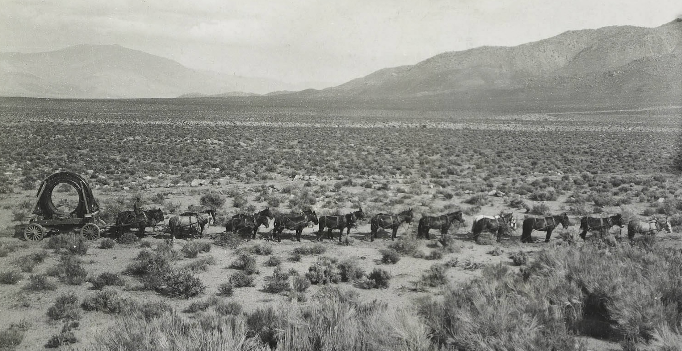
 Hauling sections of steel pipe by mule team |
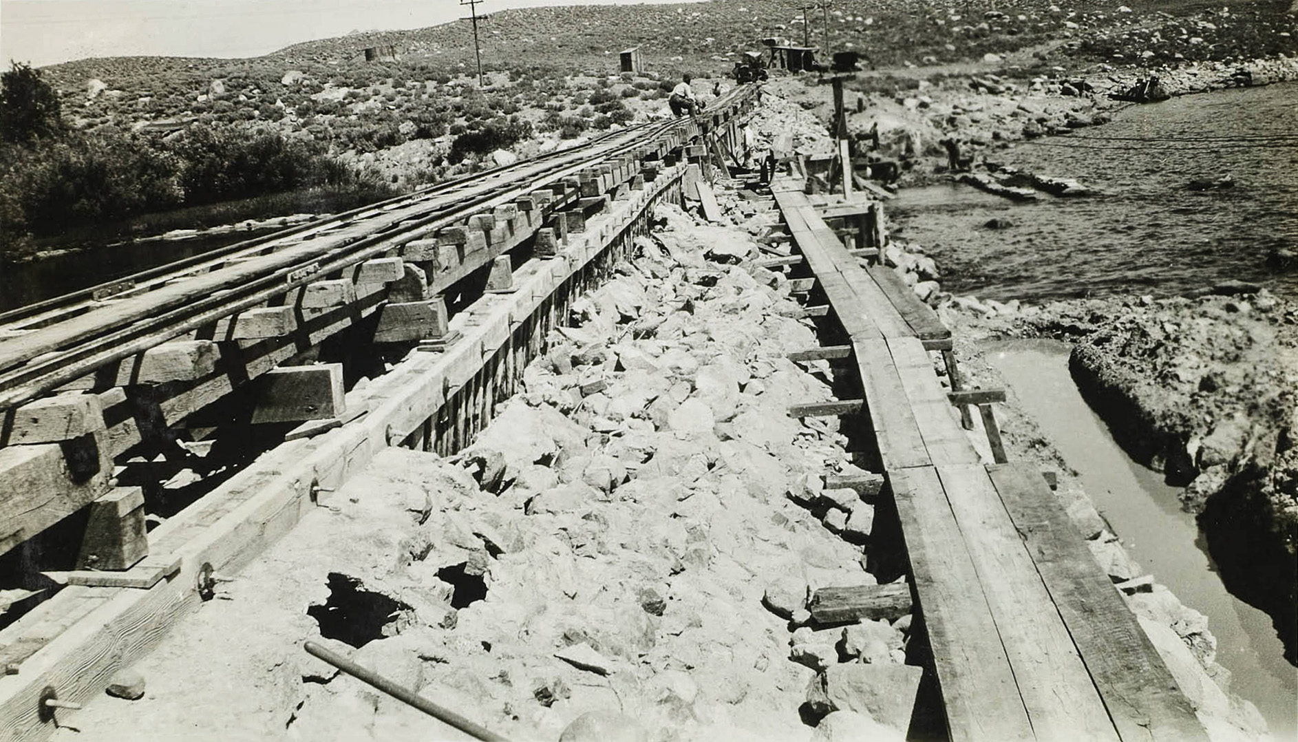
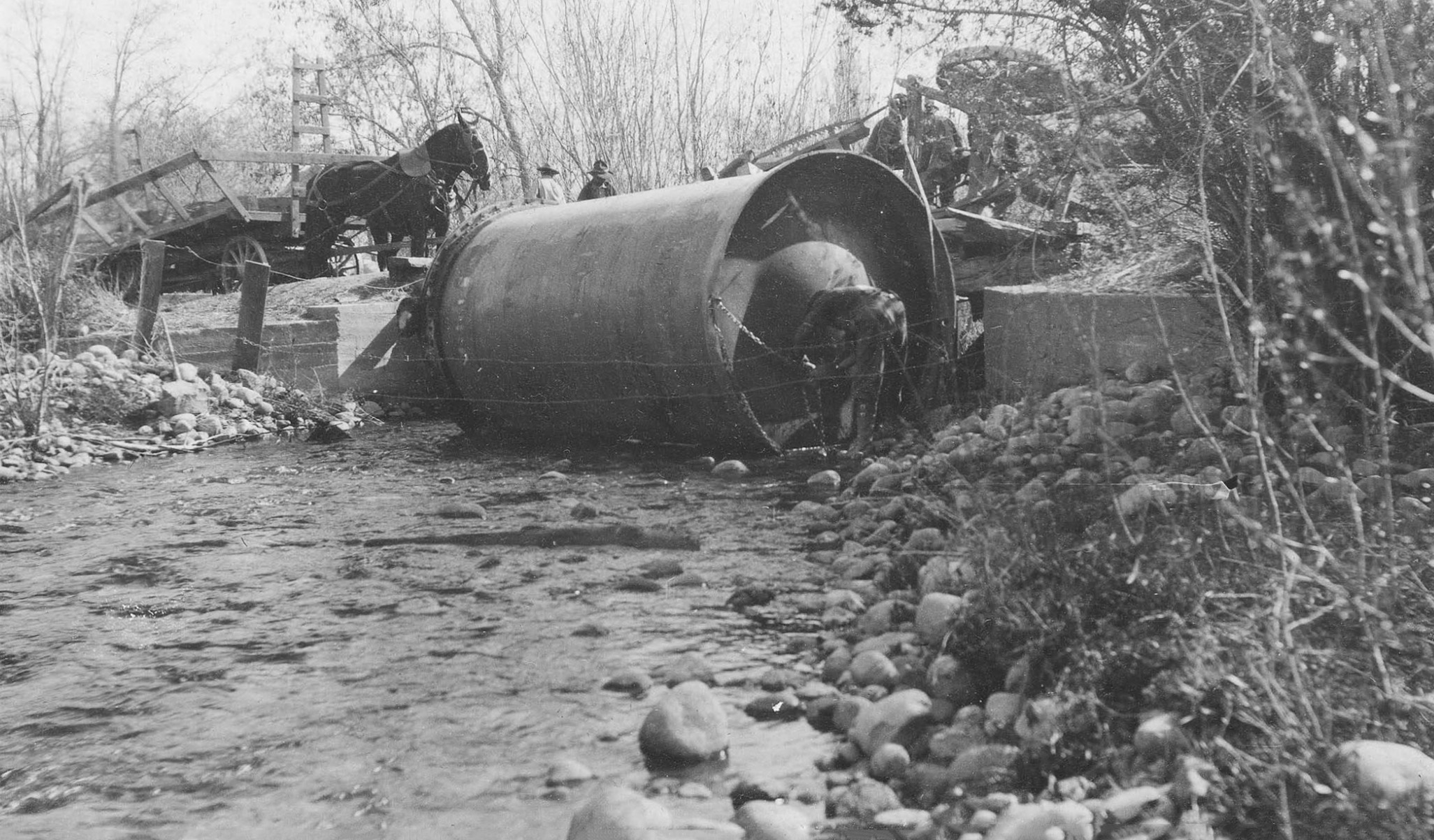 Accident at a bridge crossing. |
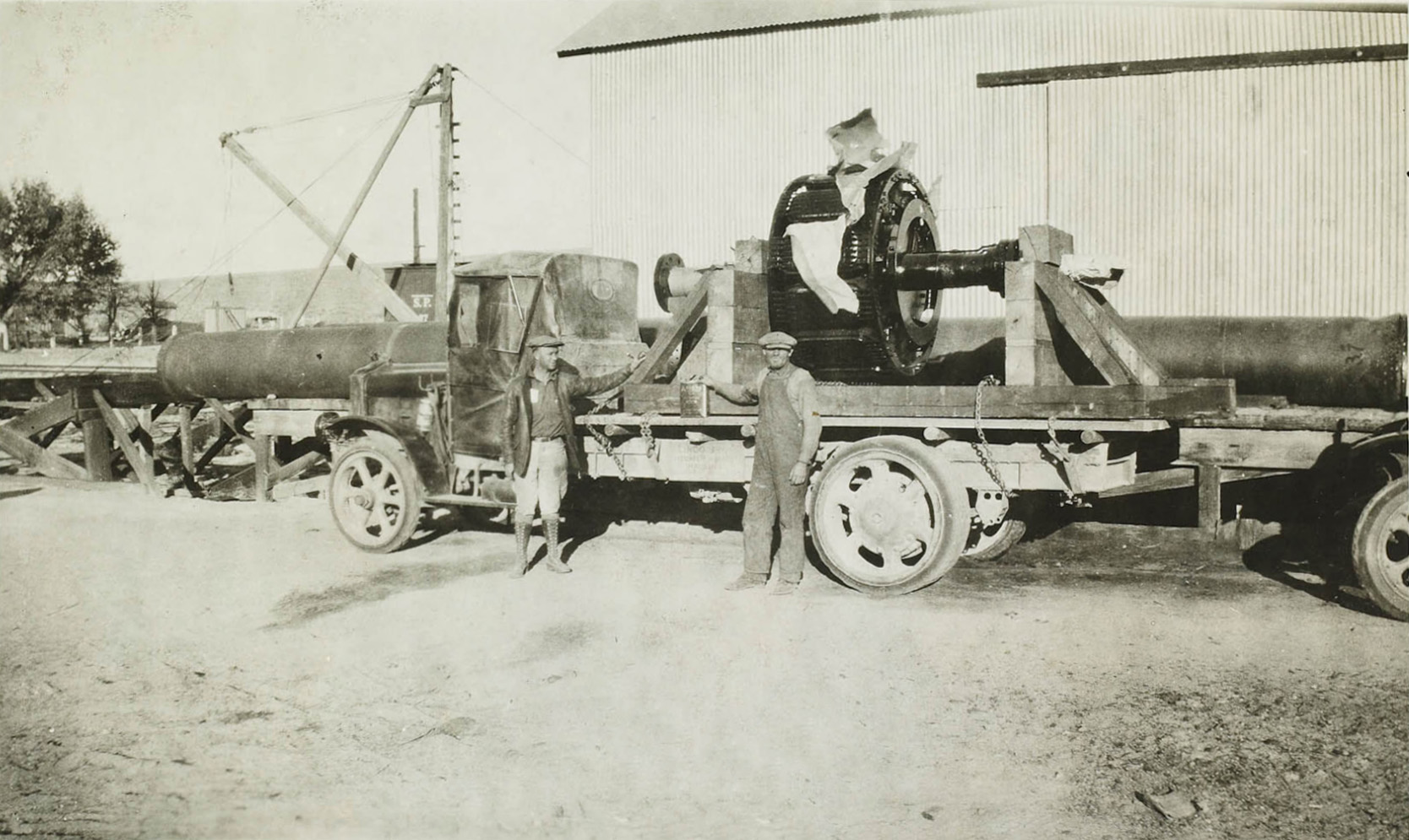
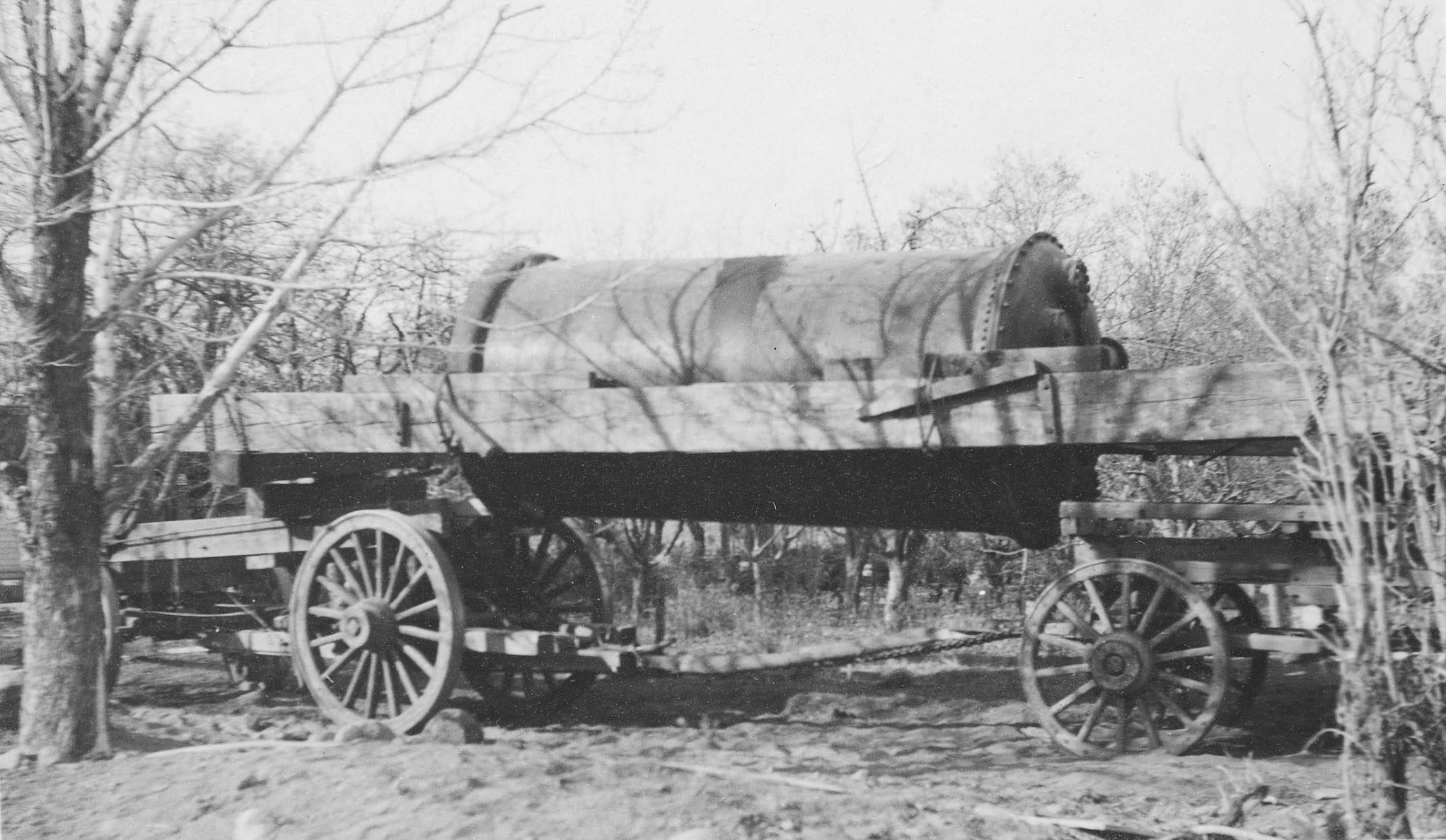
 Hauling generator section up Bishop Creek |
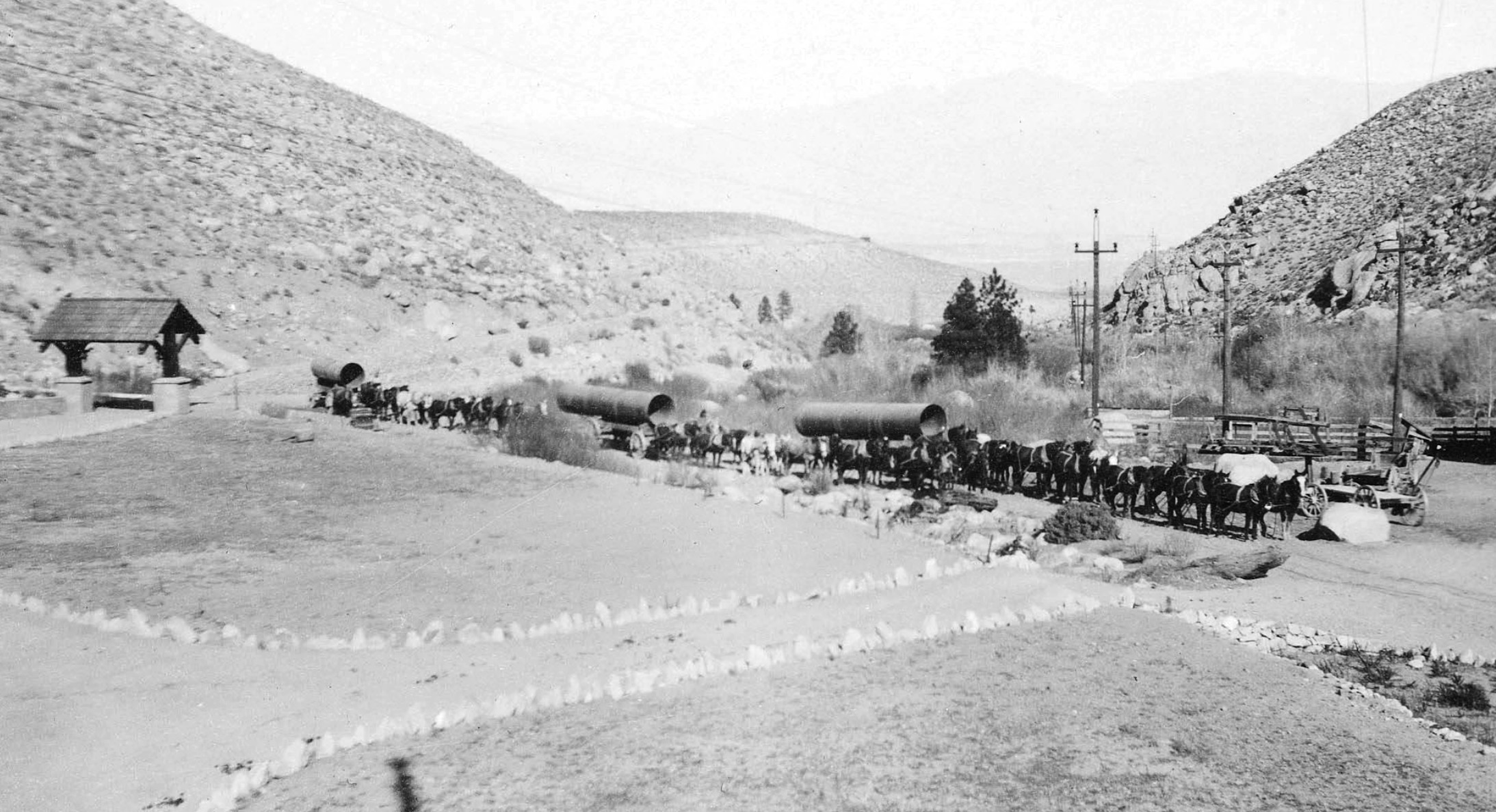 Hauling sections of steel pipe by mule team up Bishop Creek |
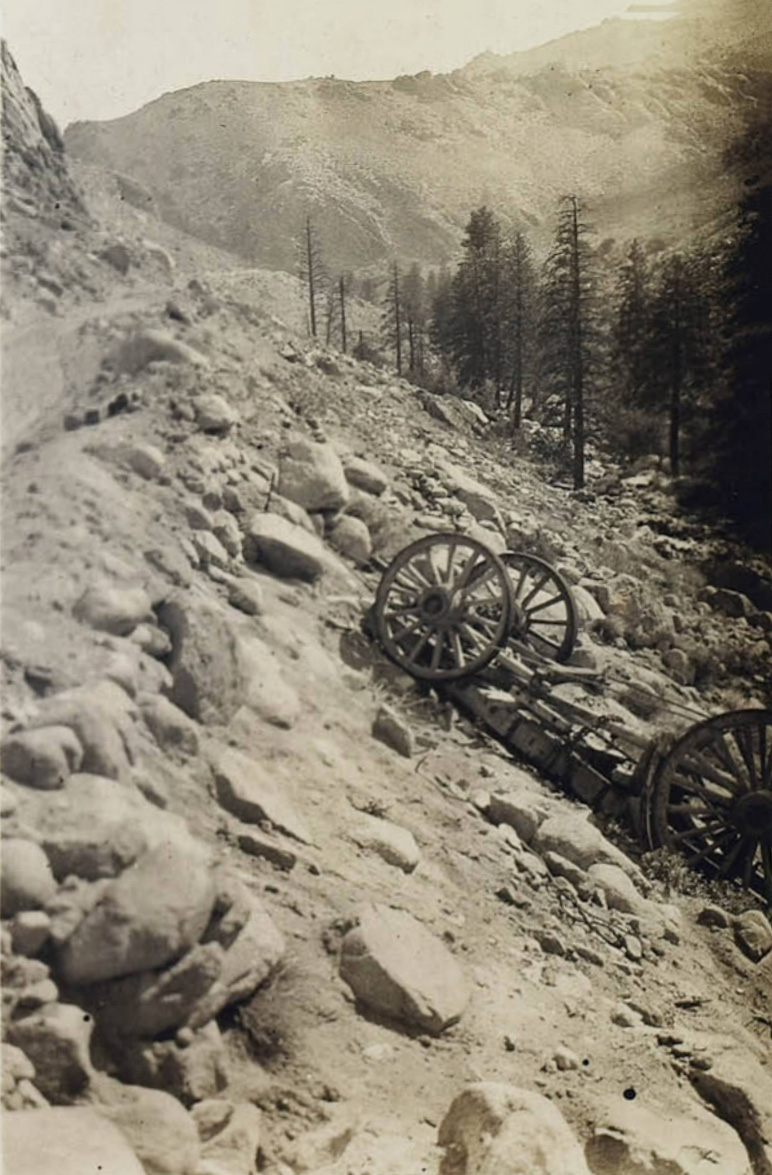 Crashed wagon between plants #3 and #4 |
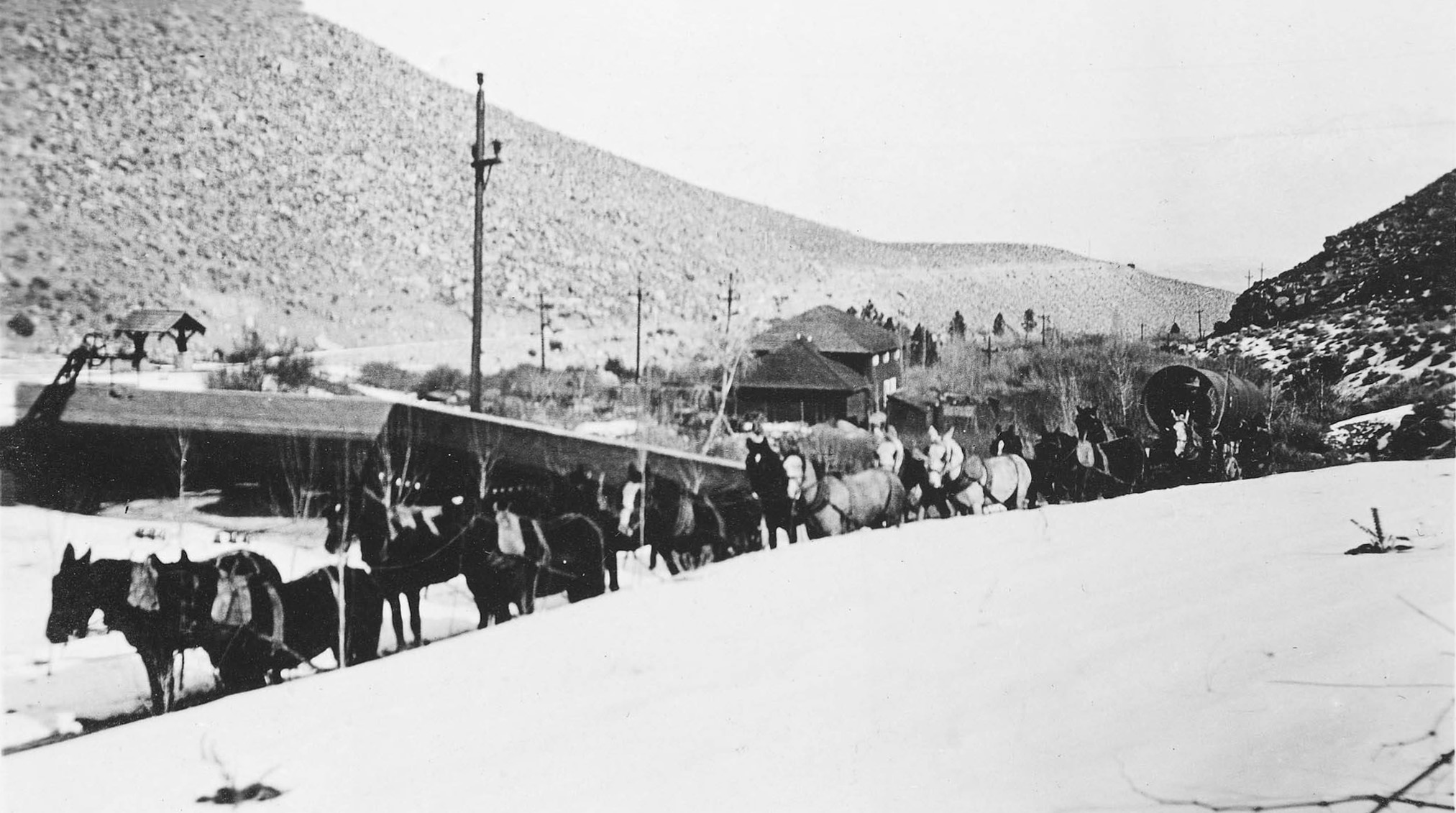
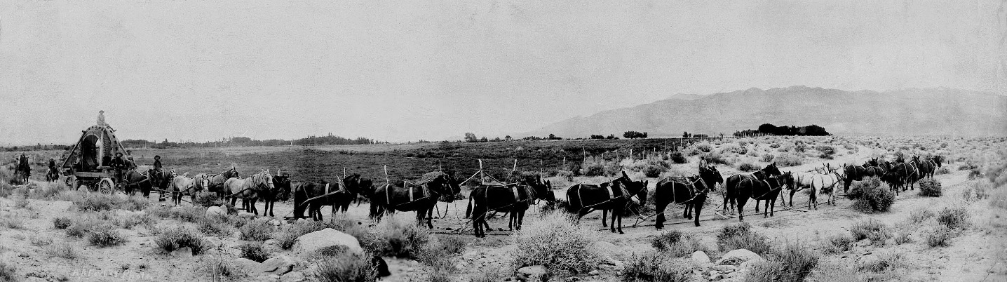
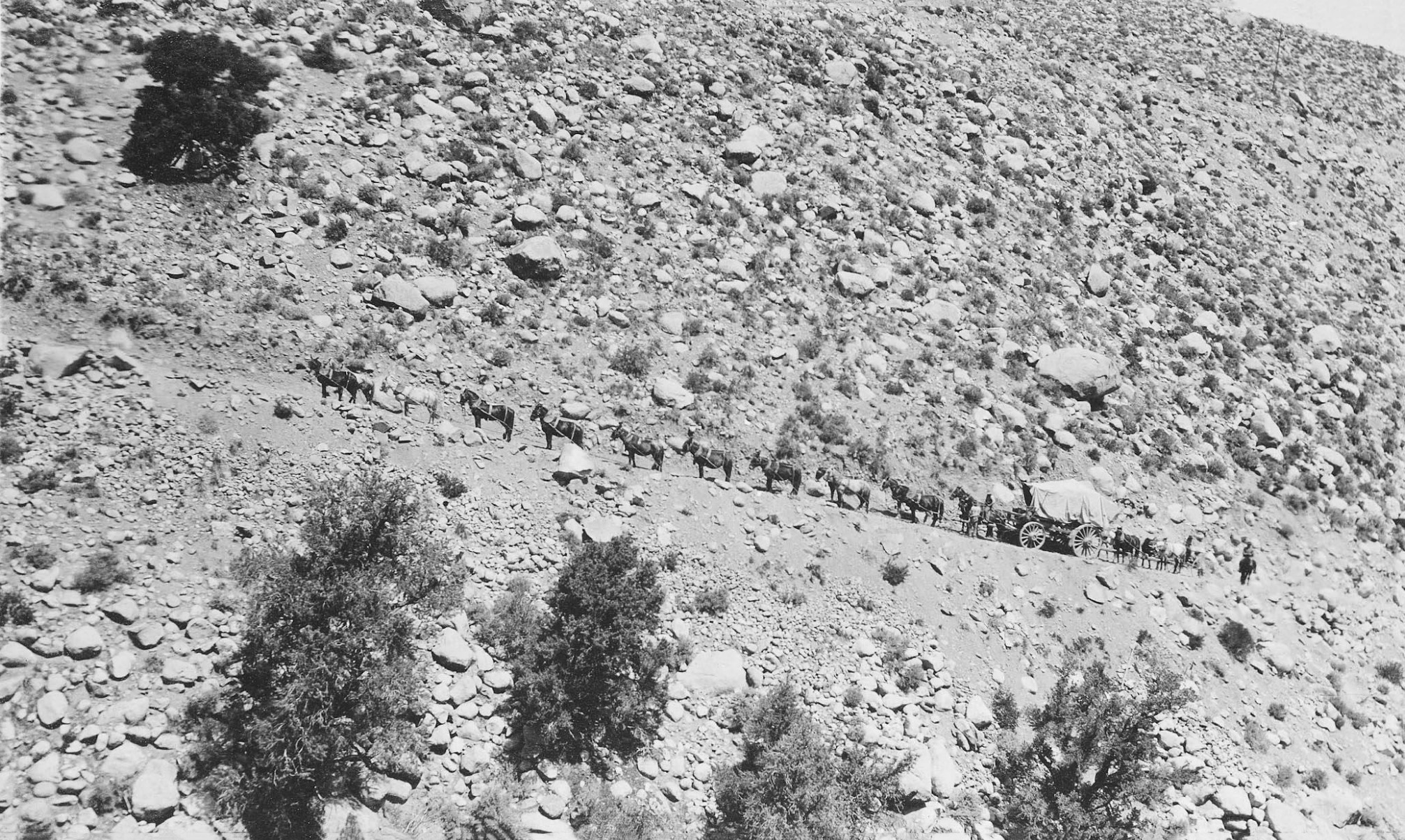 24 mule team hauling / pushing power house equipment up a Bishop Creek steep incline |
|
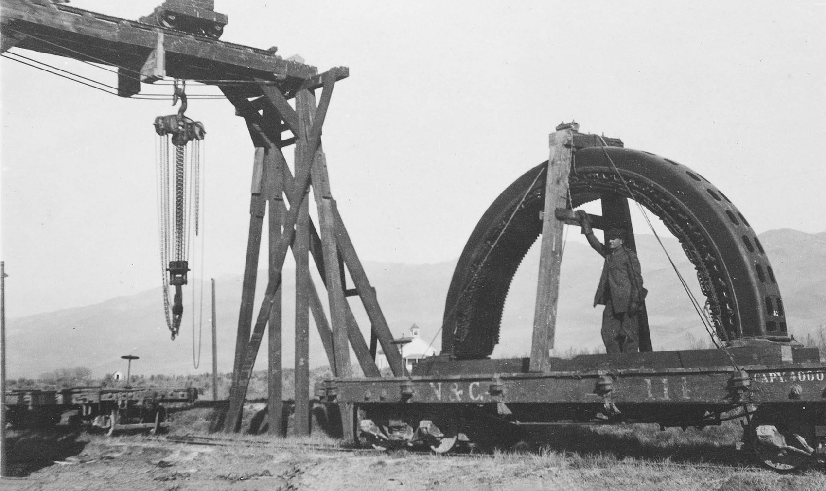
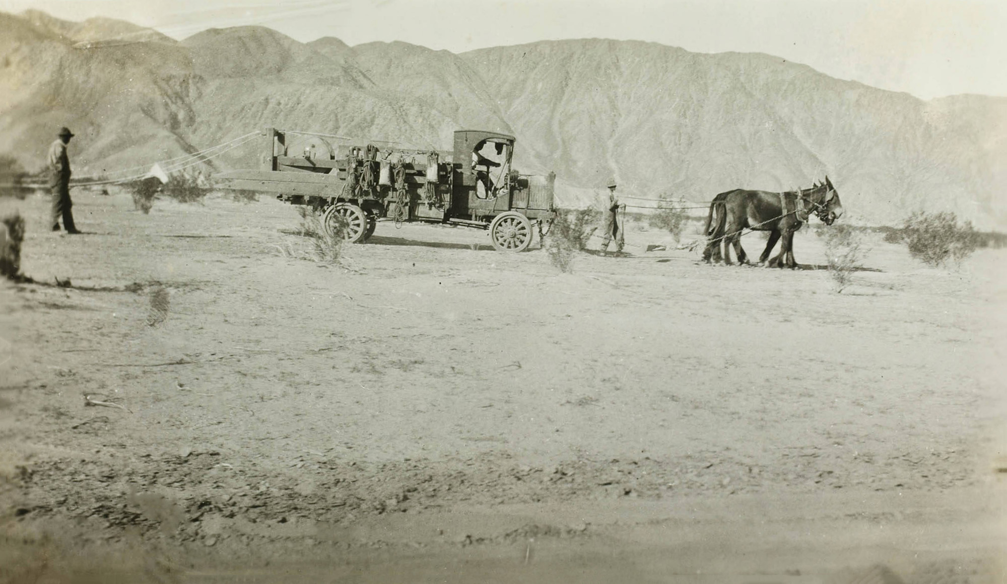
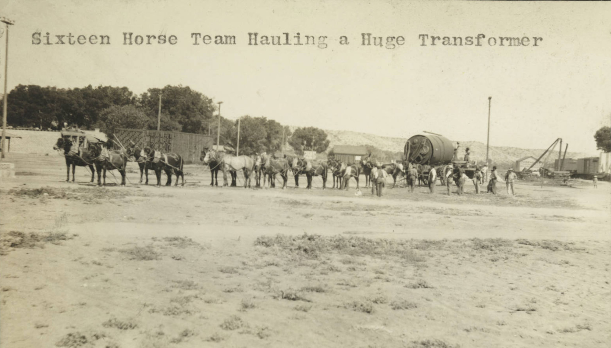 16 horse team hauling a transformer |
|
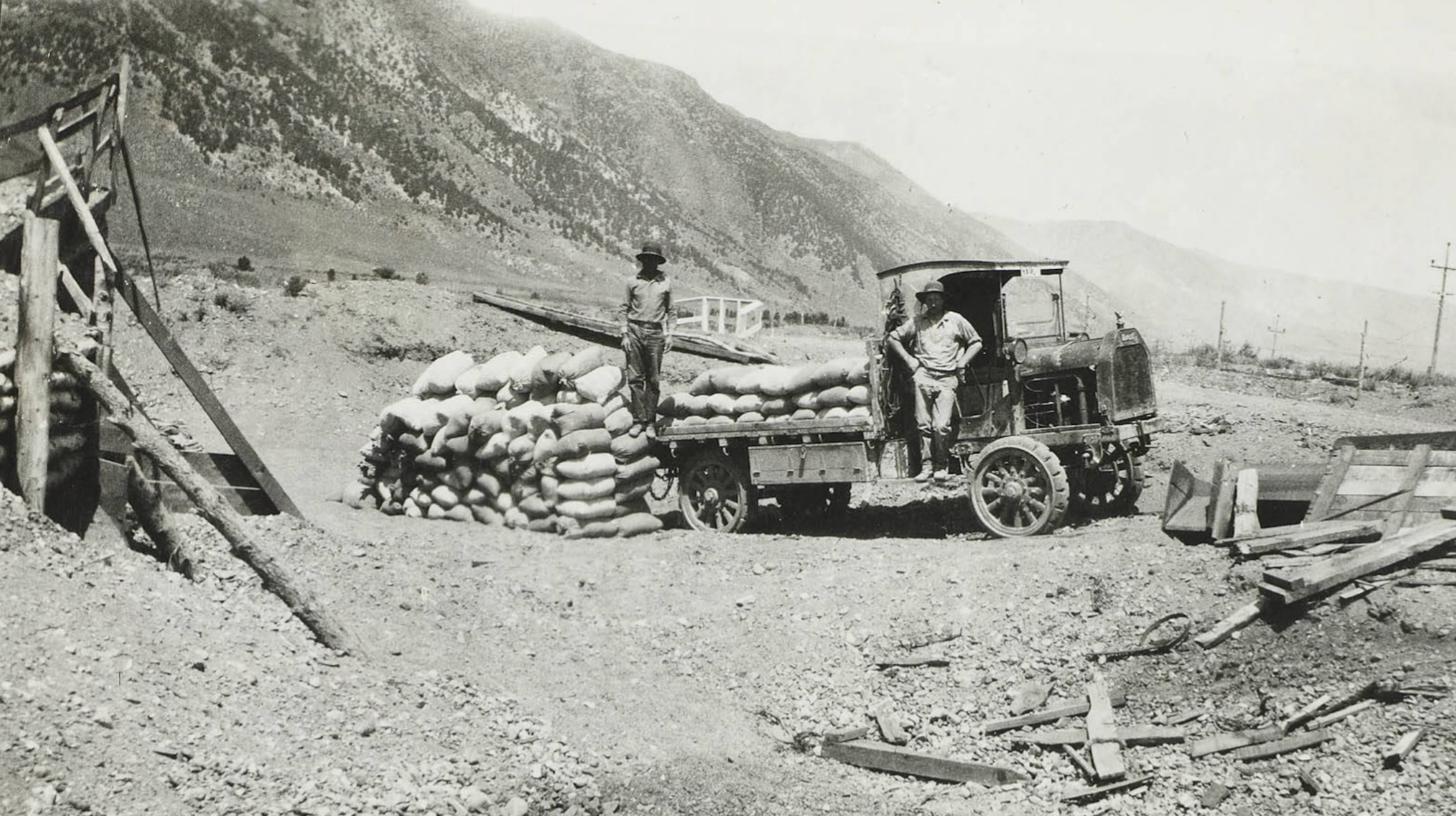
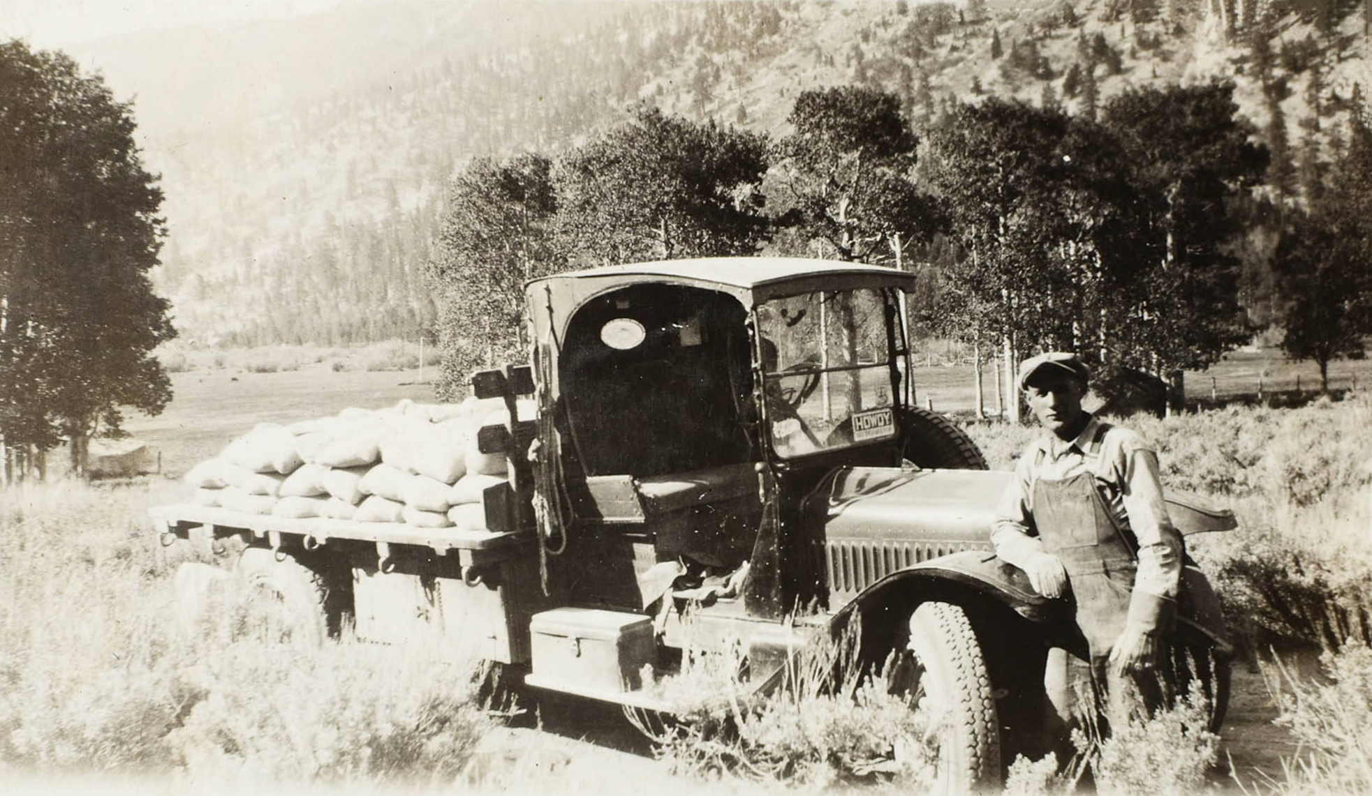 Transporting cement by truck |
|
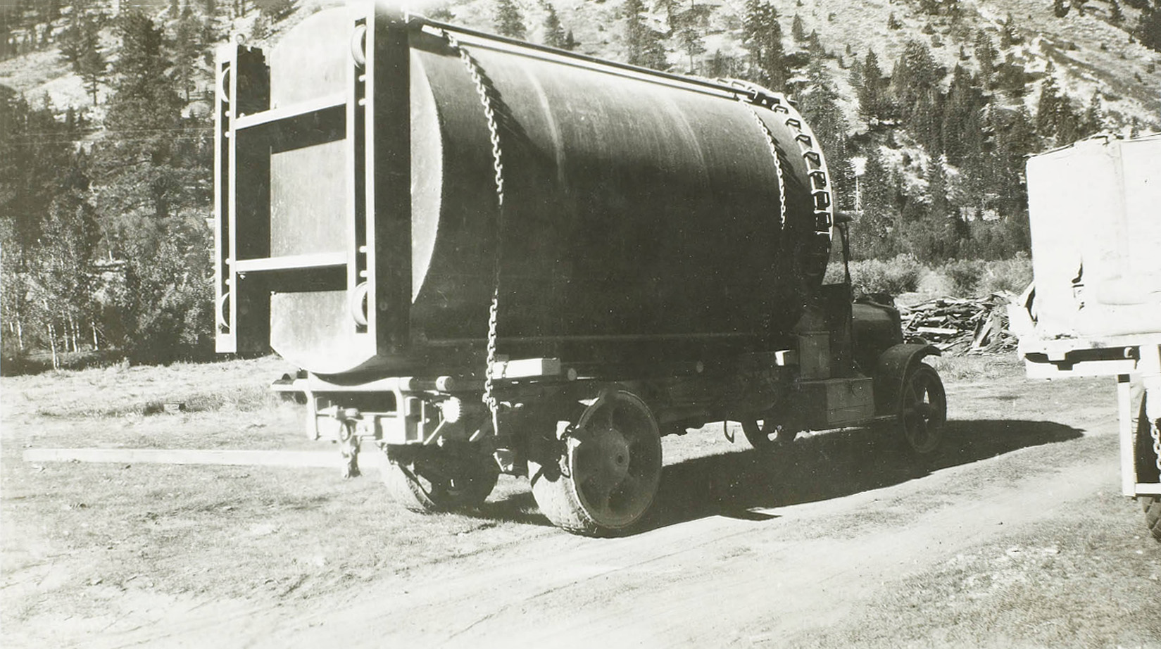
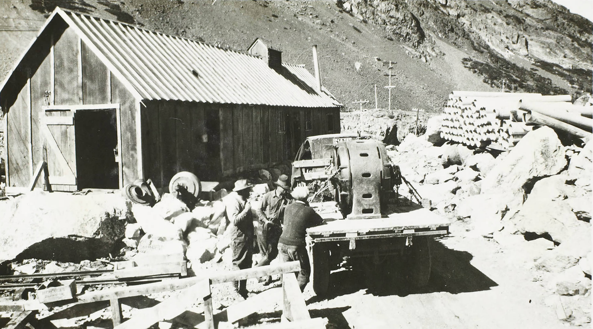 Transporting a generator by truck |
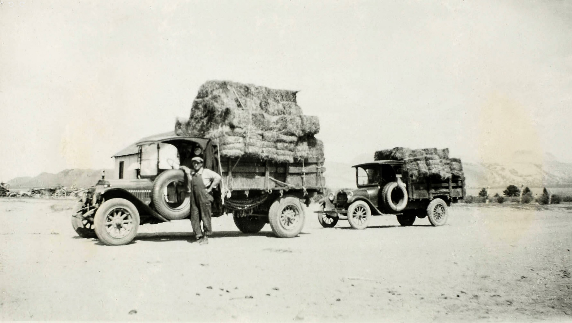 Hauling a load of hay for the livestock |
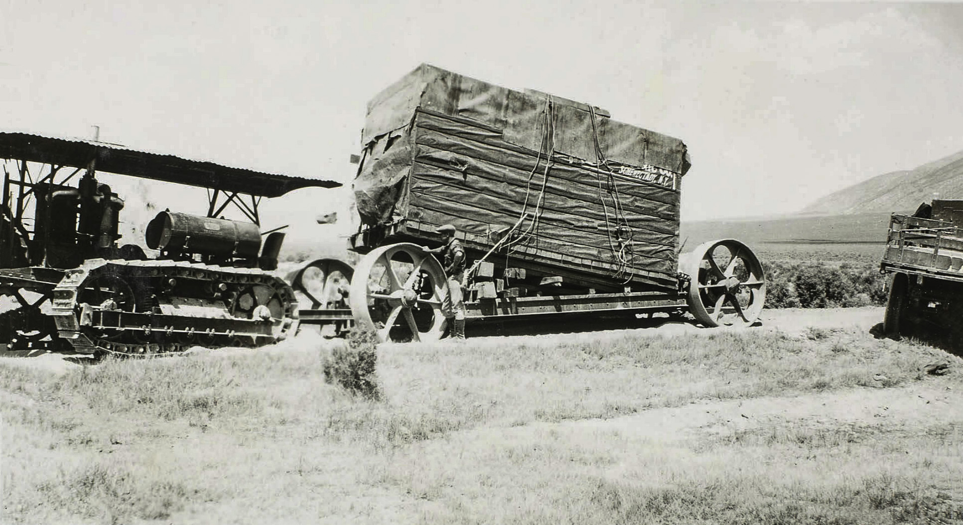 Transporting a transformer by tractor |
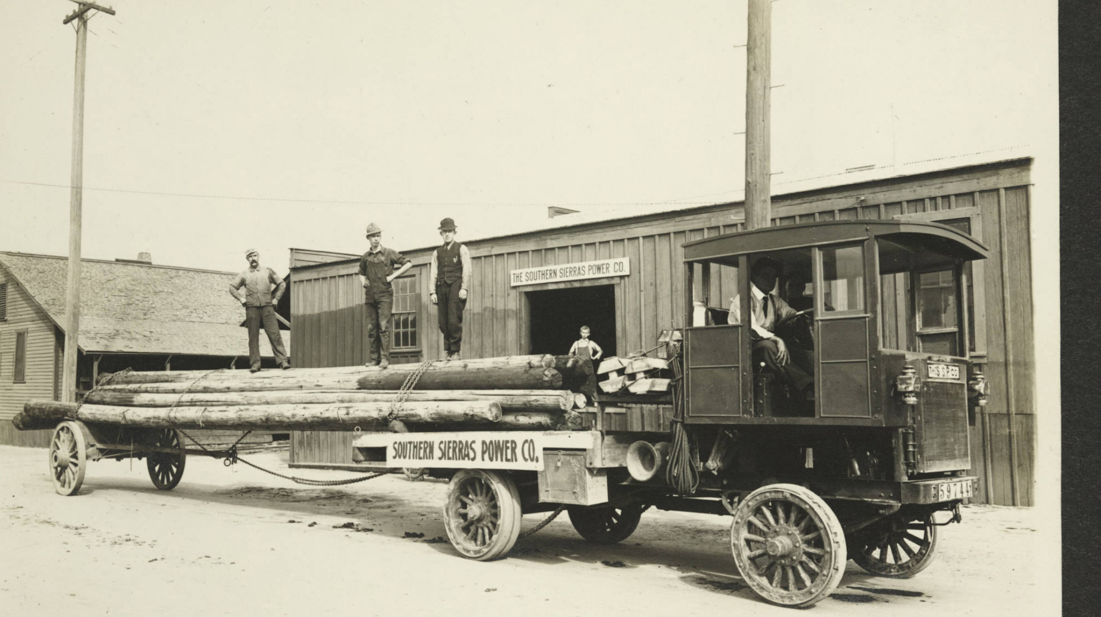
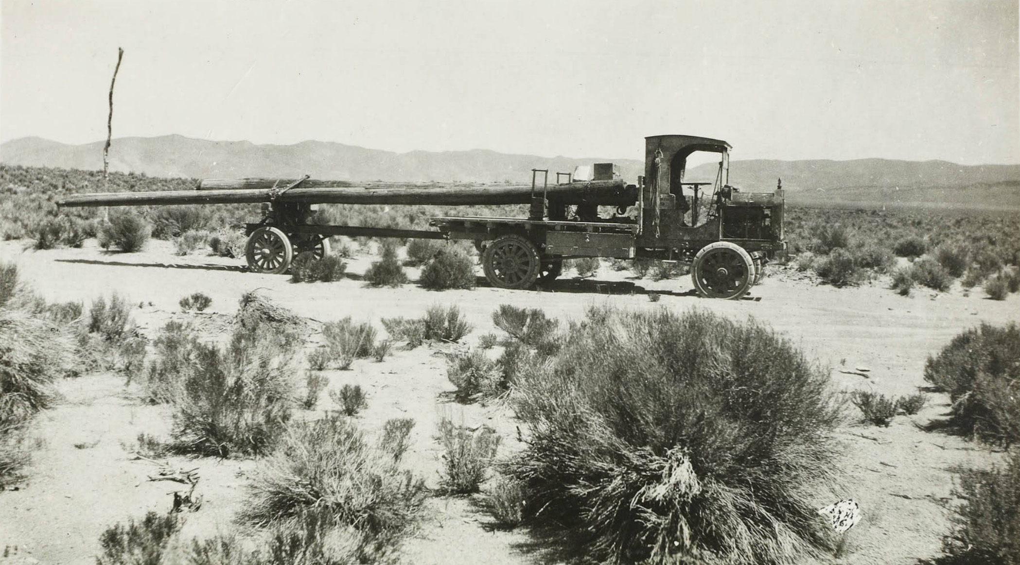
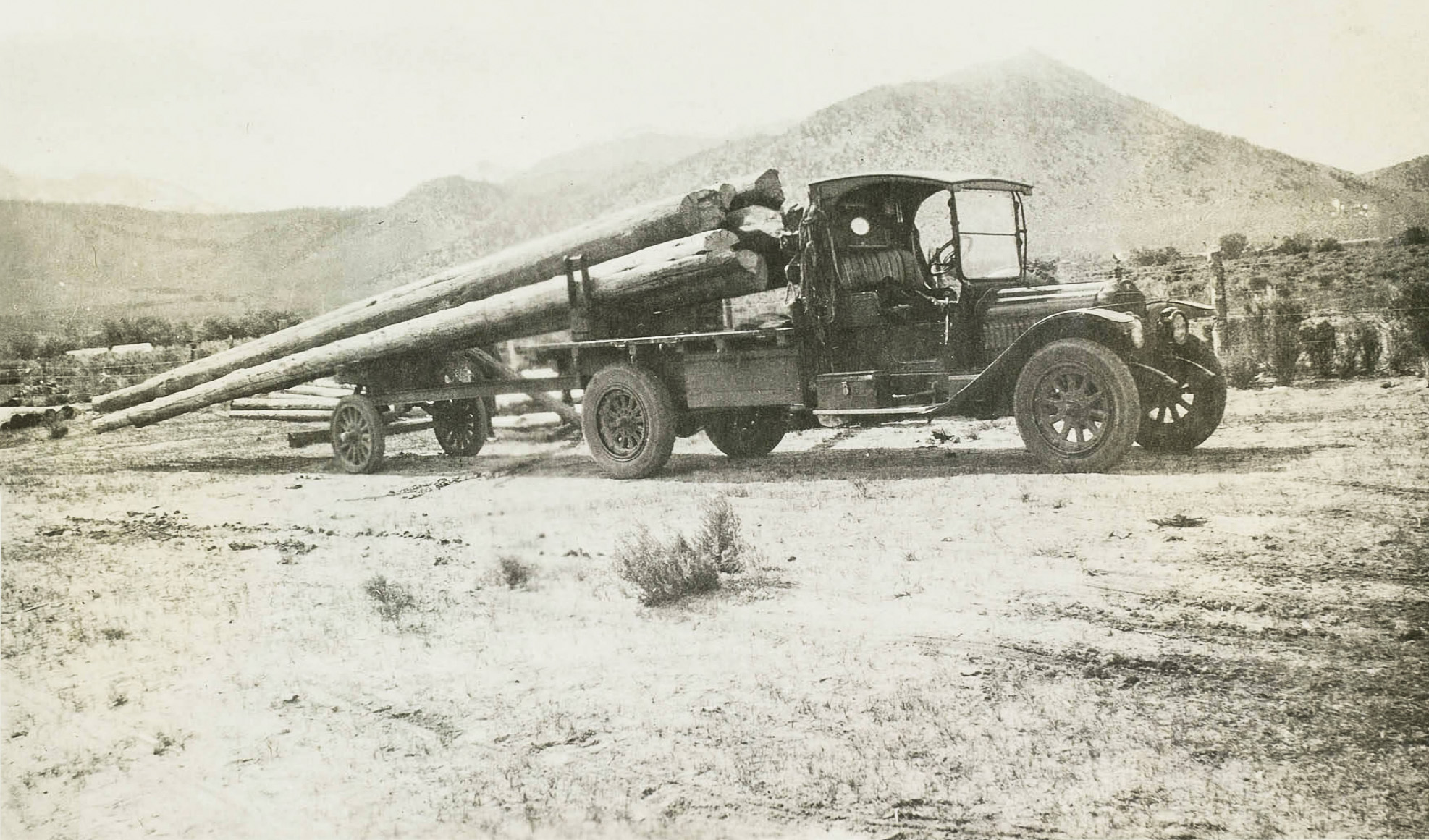
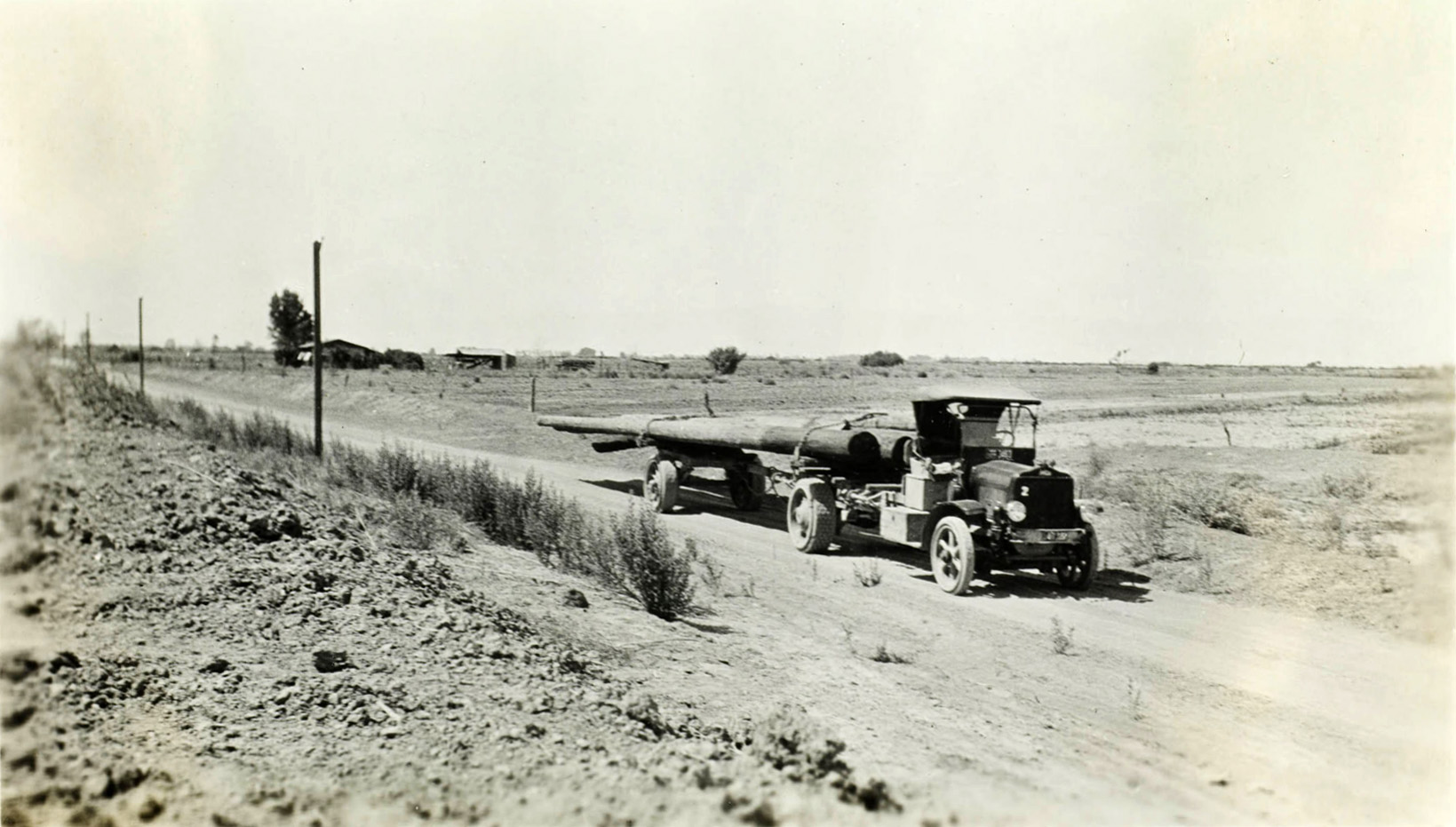
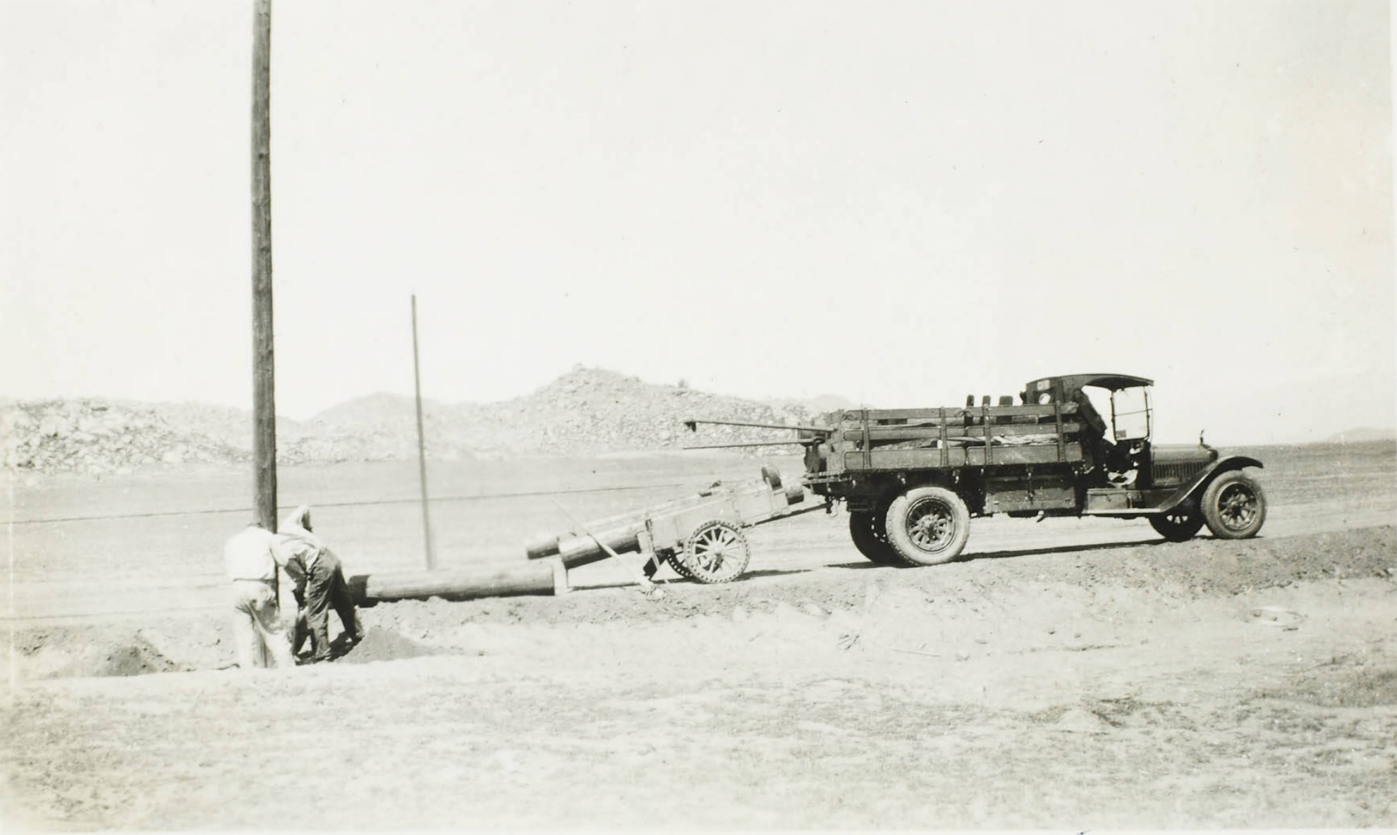
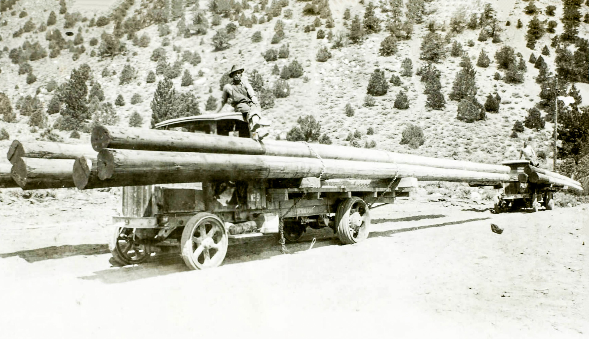 Transporting 55' long power poles for transmission lines. |
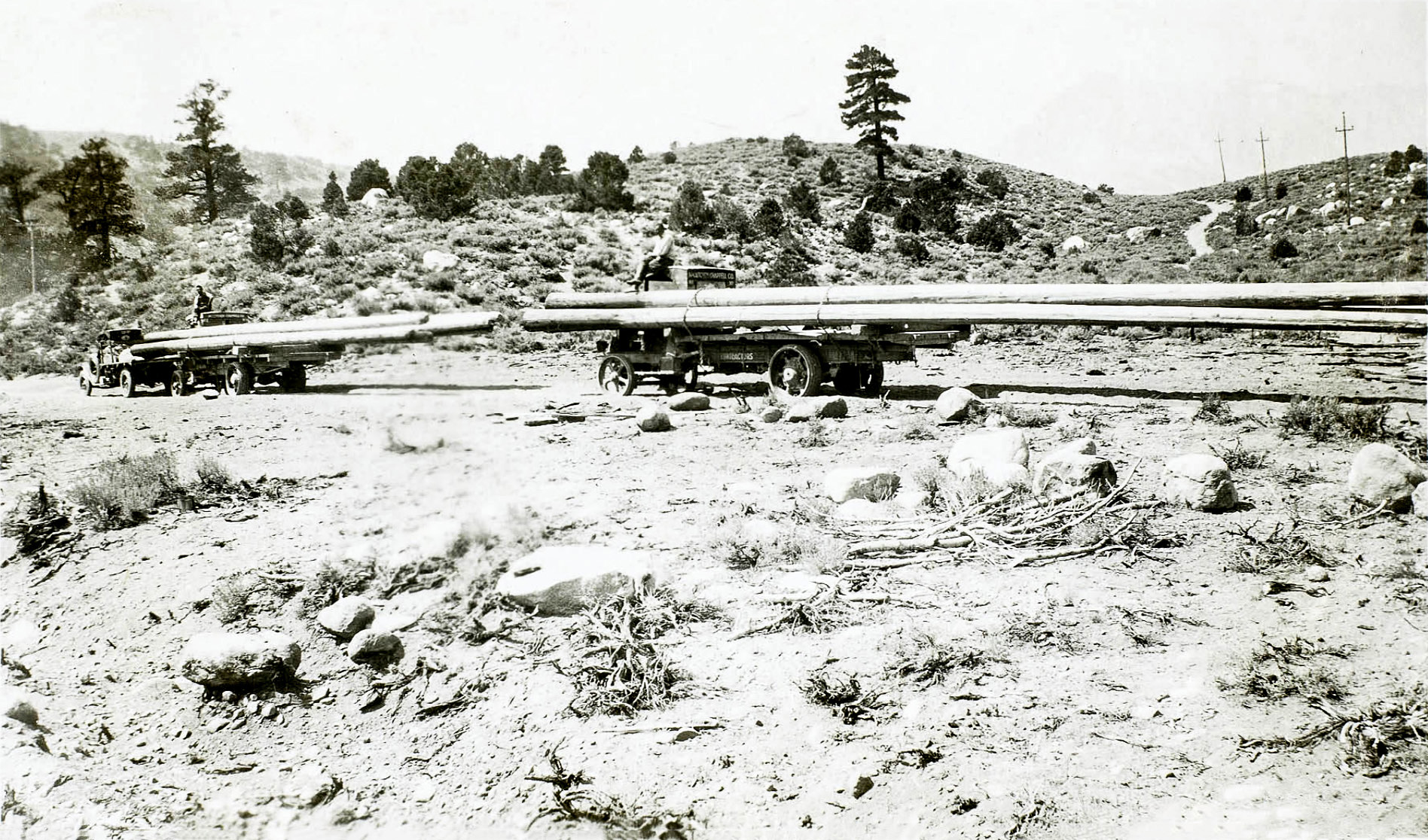 Transporting 55' long power poles for transmission lines. |
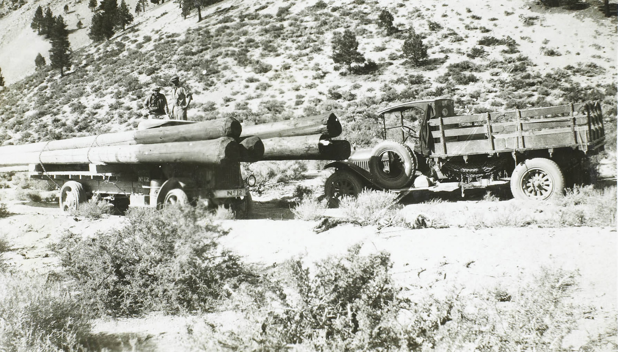 Transporting 55' long power poles for transmission lines. |
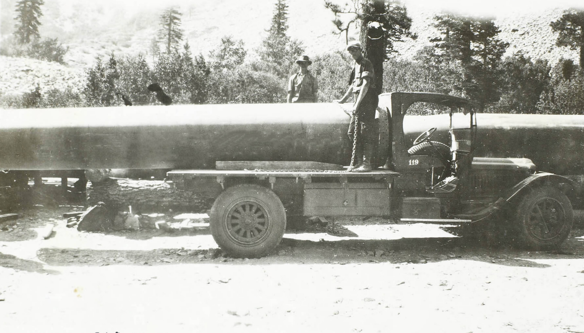 Hauling steel pipe to the powerhouses |
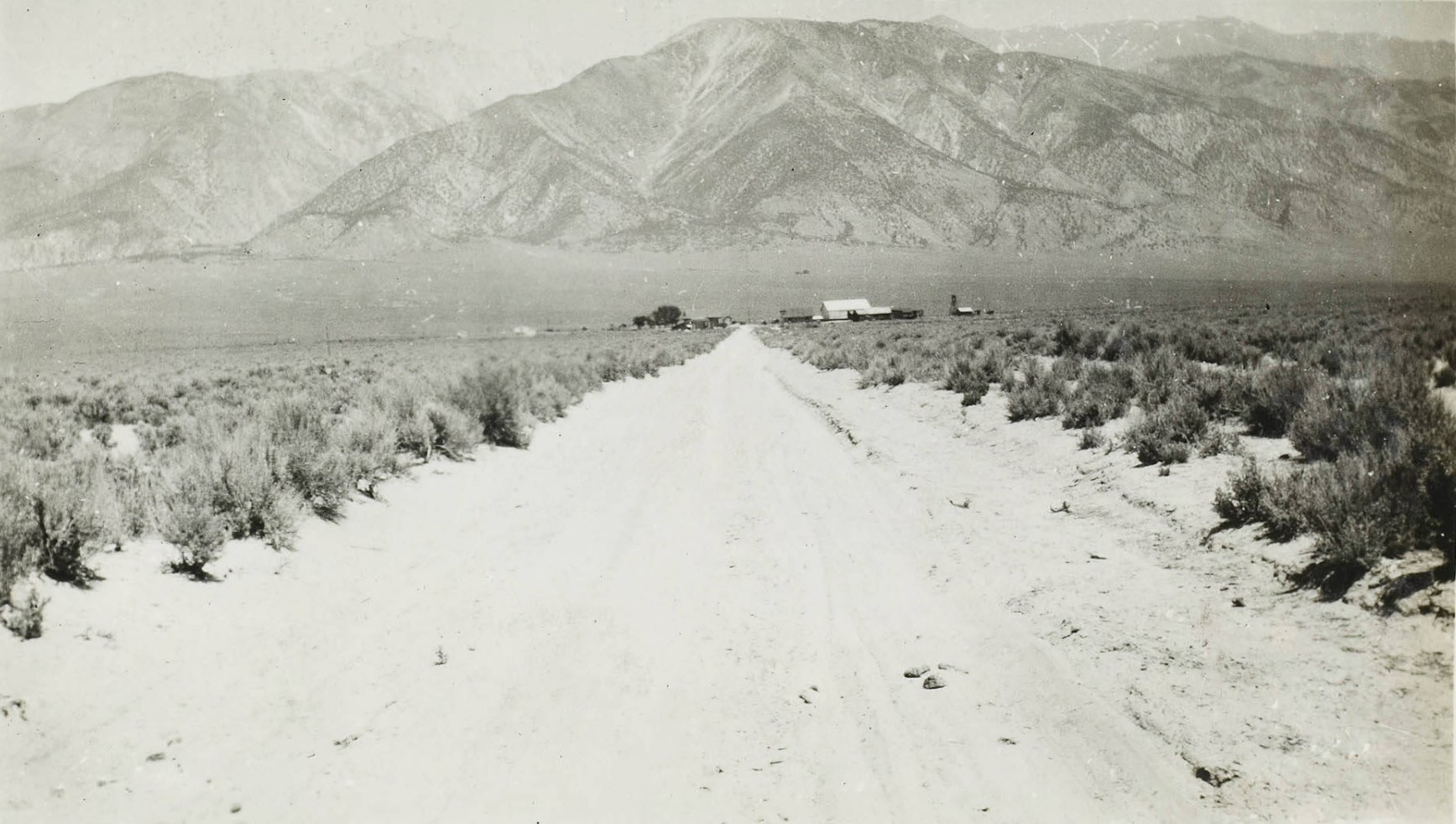
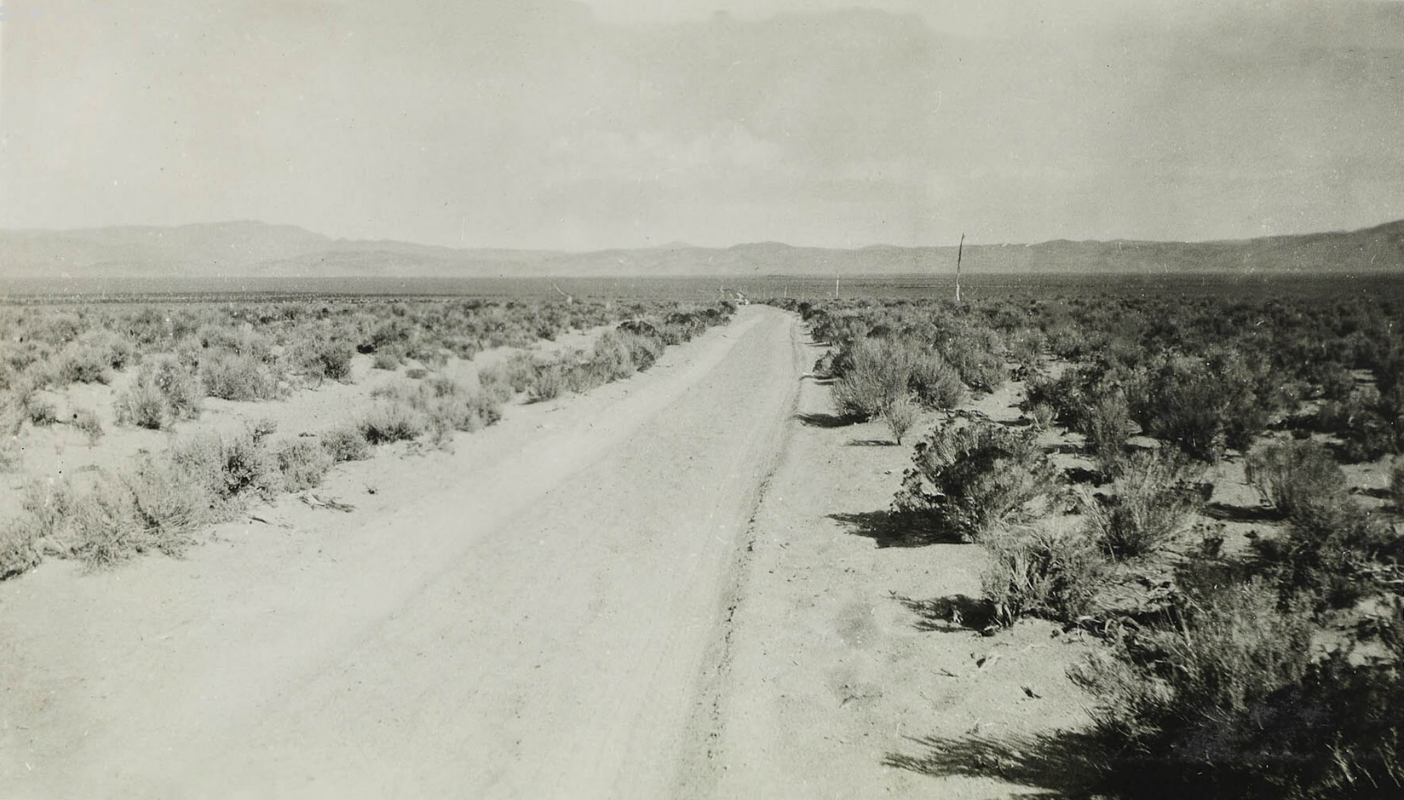
 On the road between Laws and Benton |
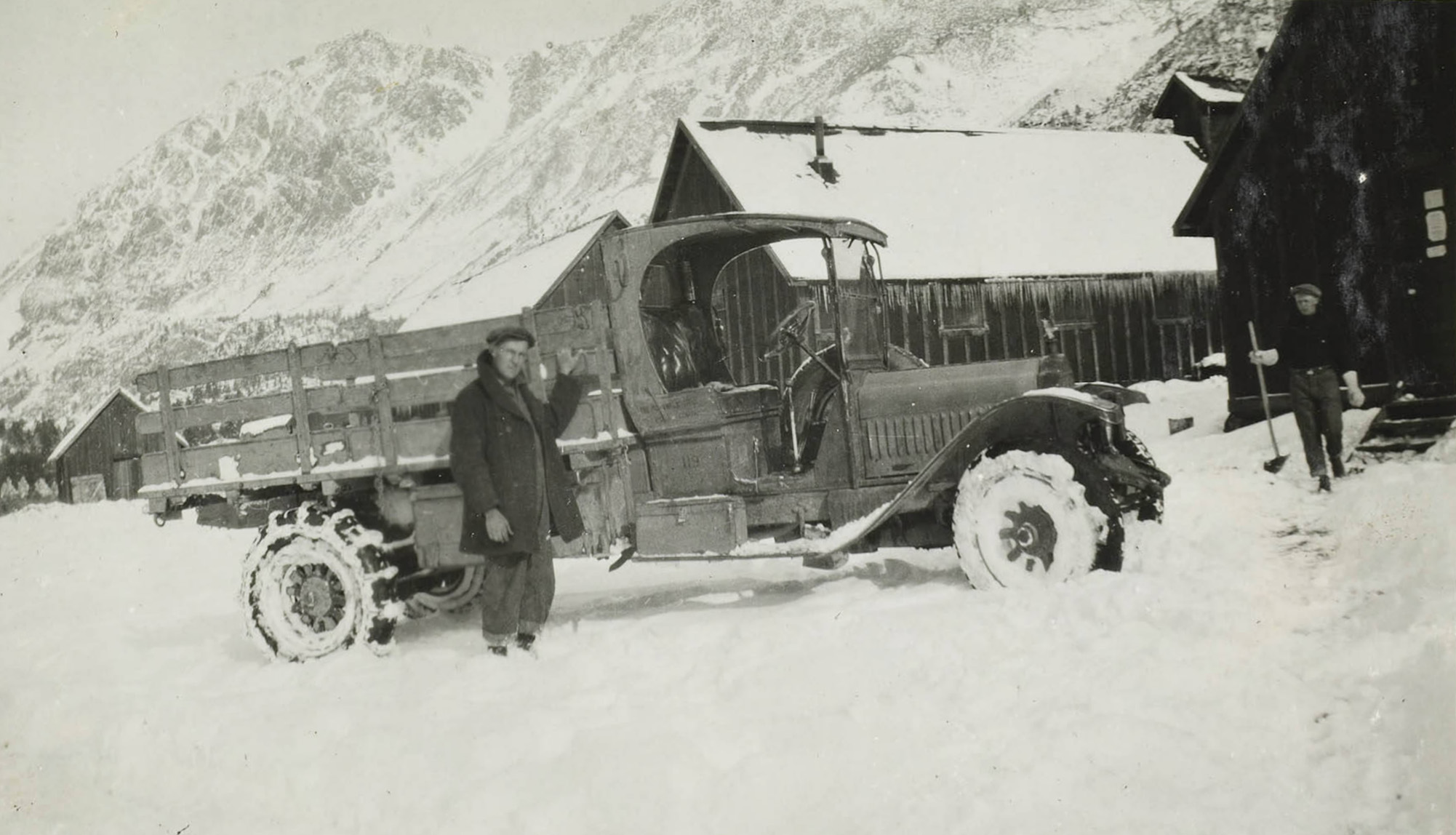
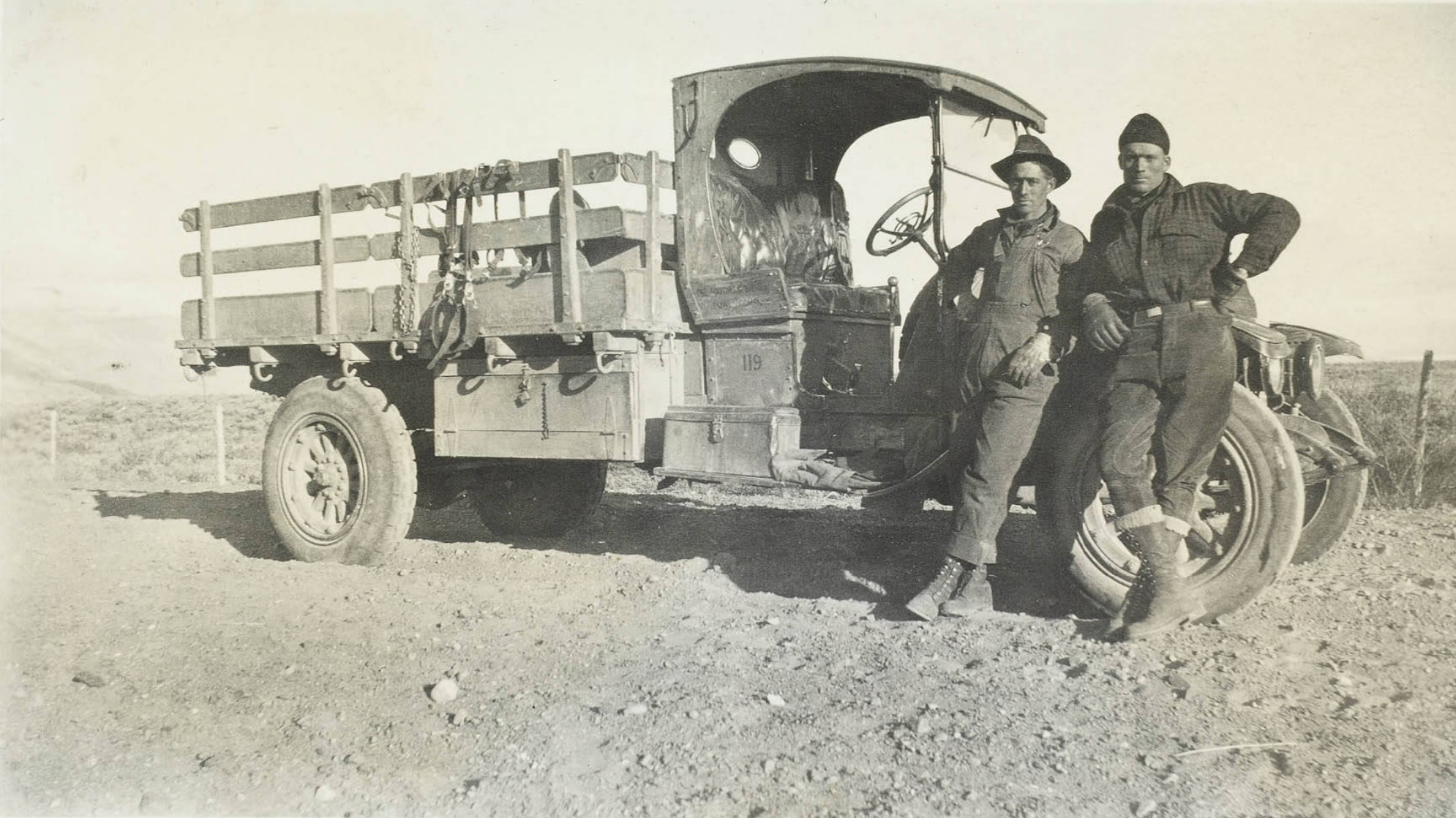
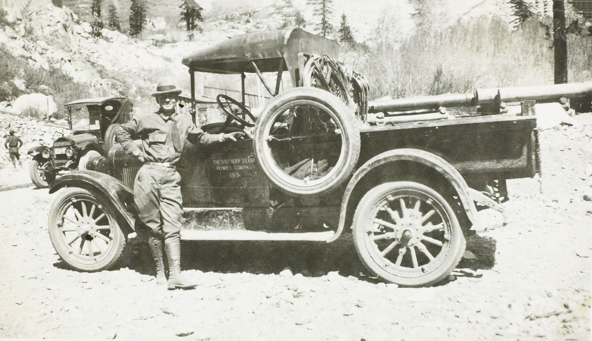 Southern Sierras Power Company truck |
 Transporting a 7.5 ton transformer to one of the powerhouses |
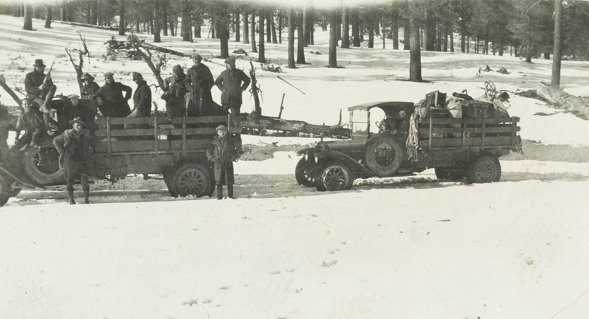
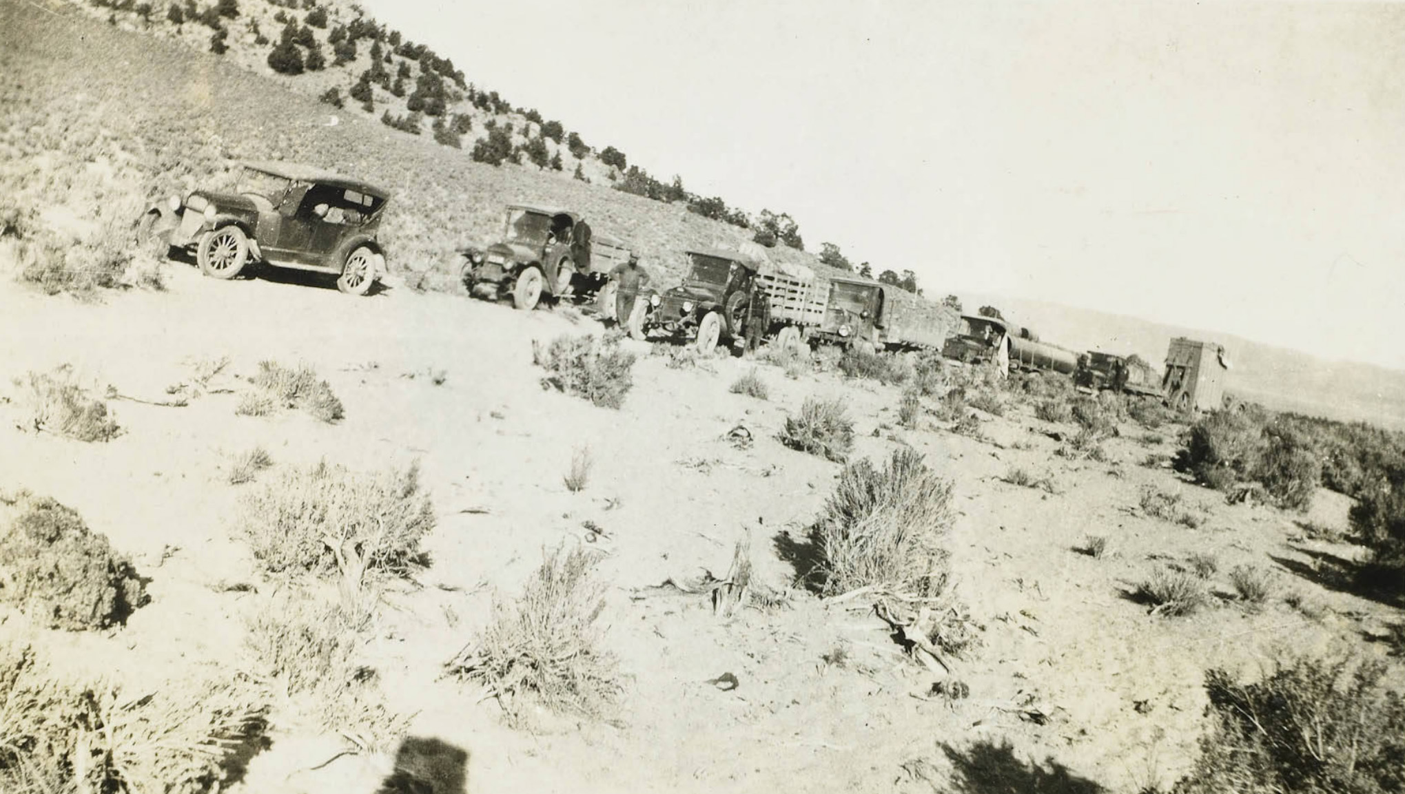
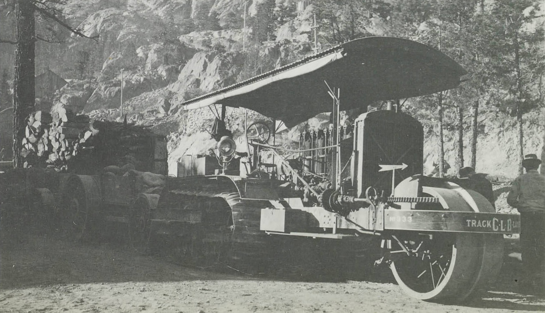
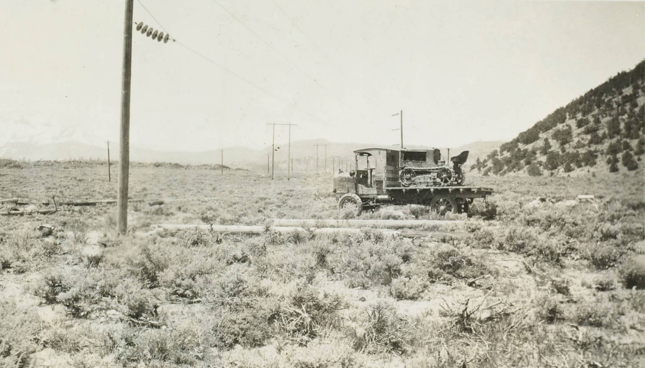
 One of six caterpillar engines hauling freight 56 miles from Benton to Silver Lake |
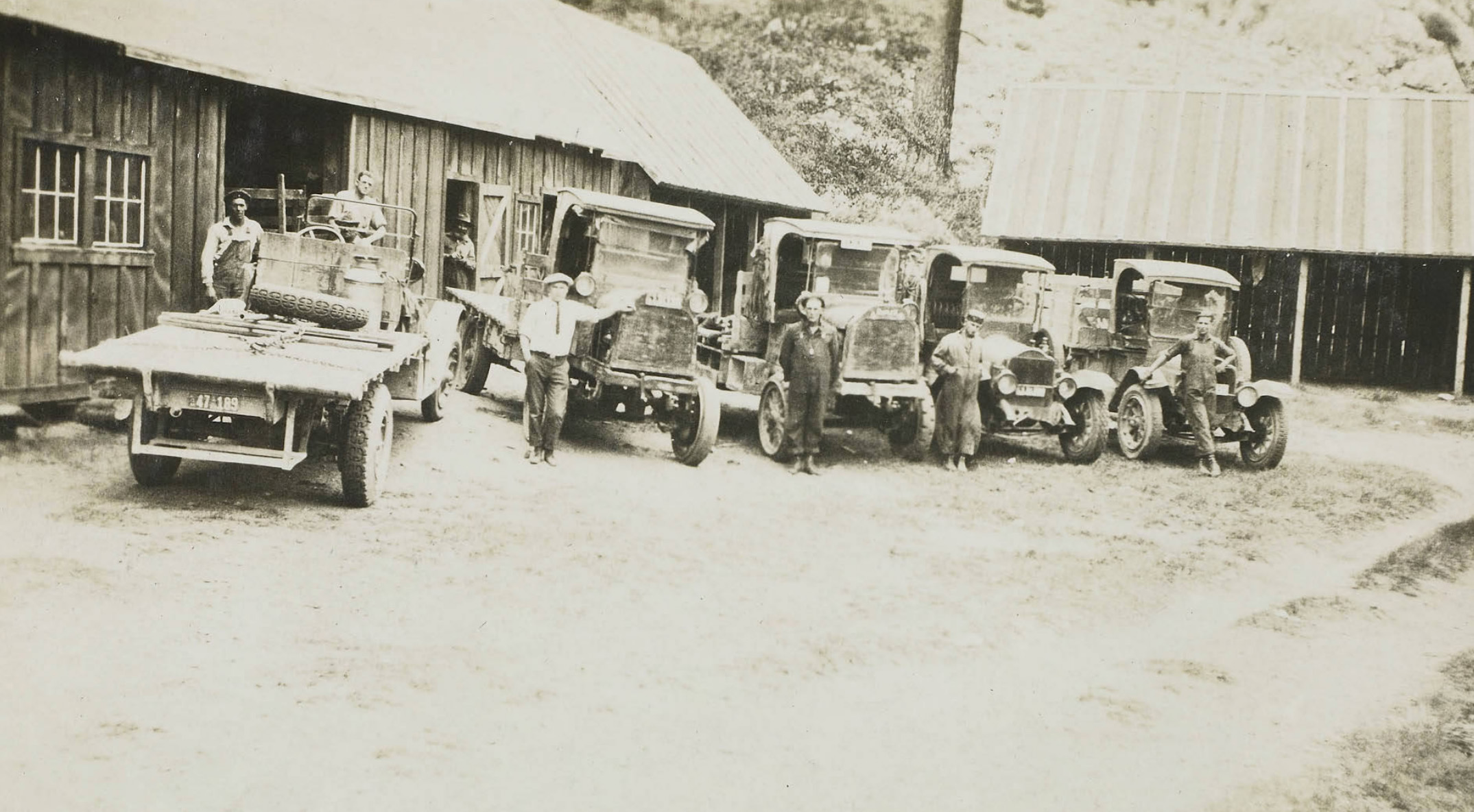 Fleet of trucks ready for work |
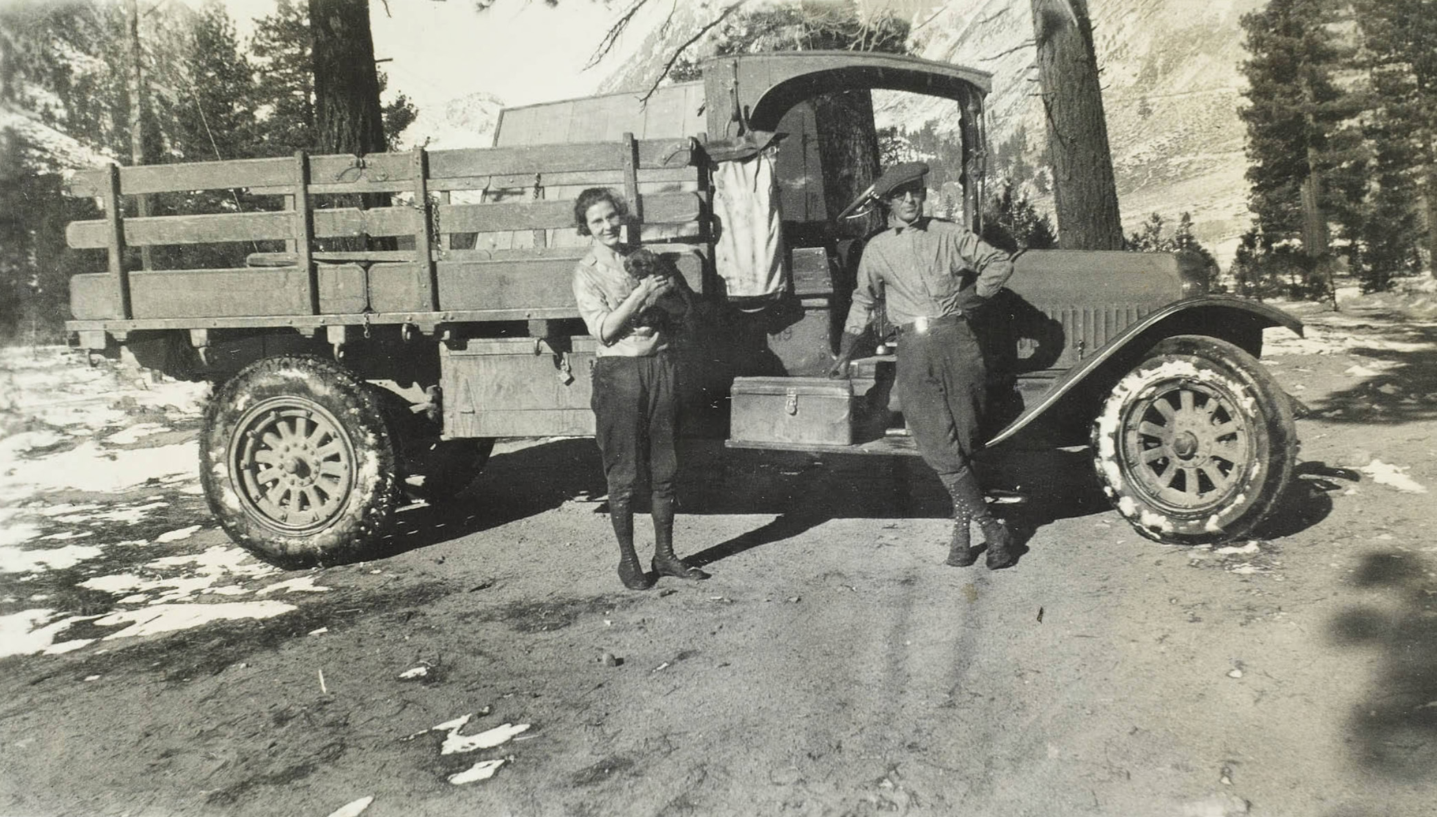
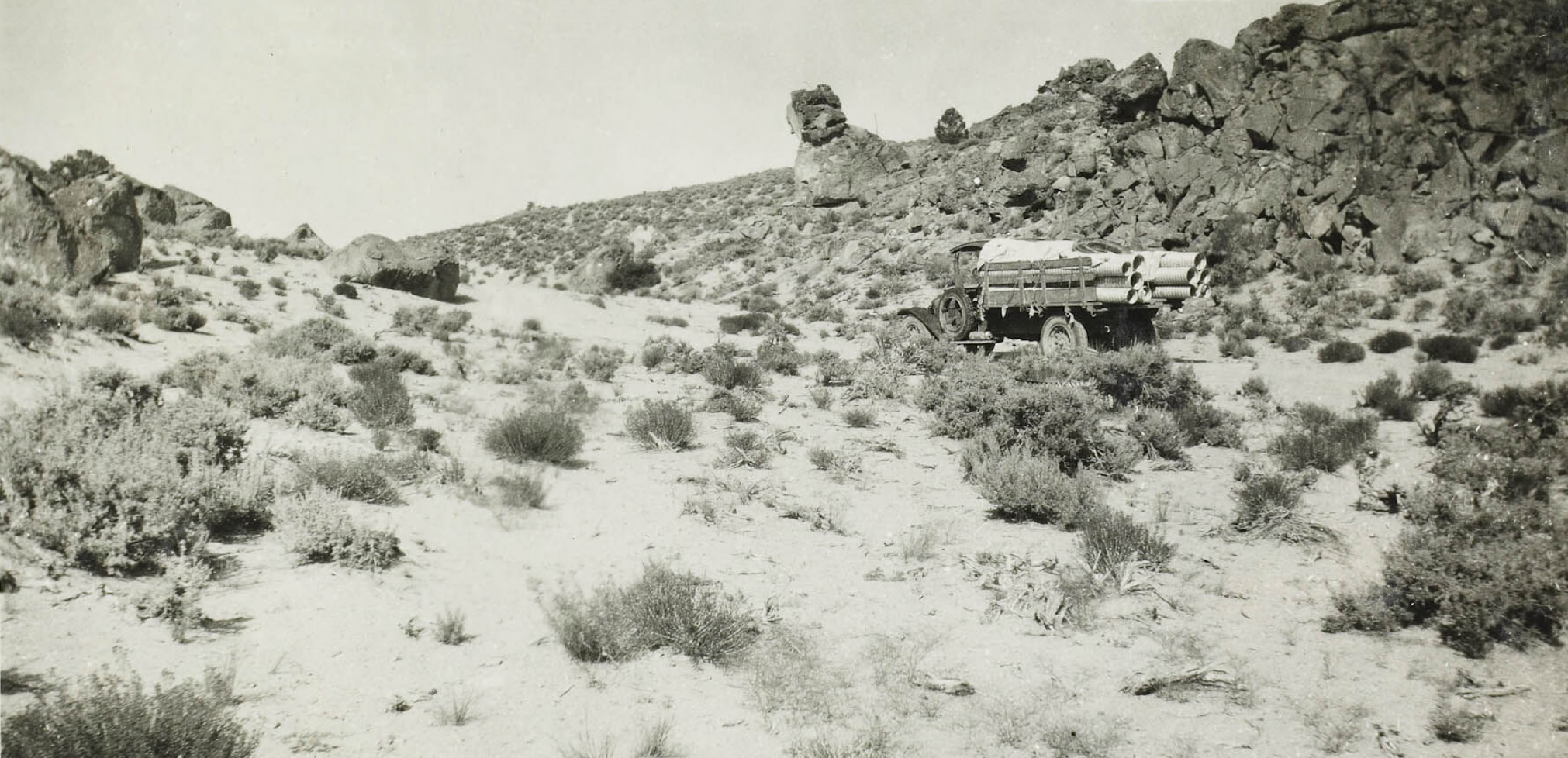
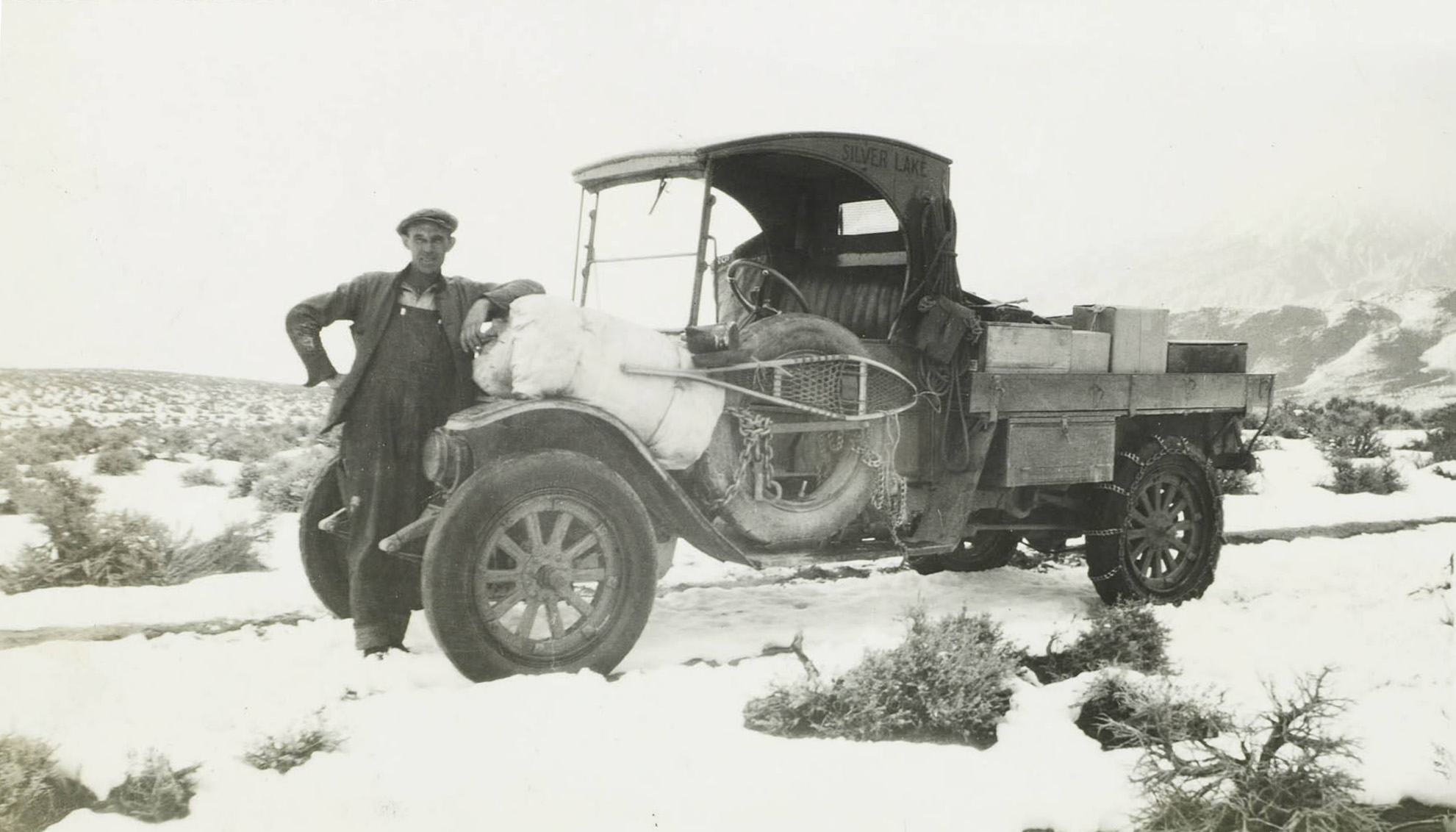
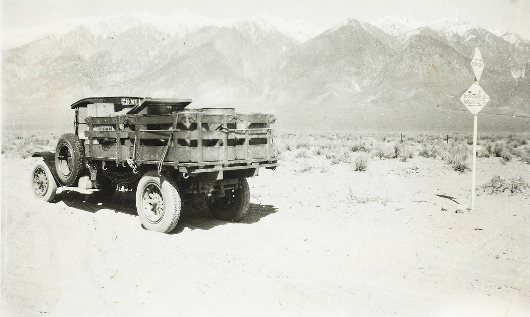
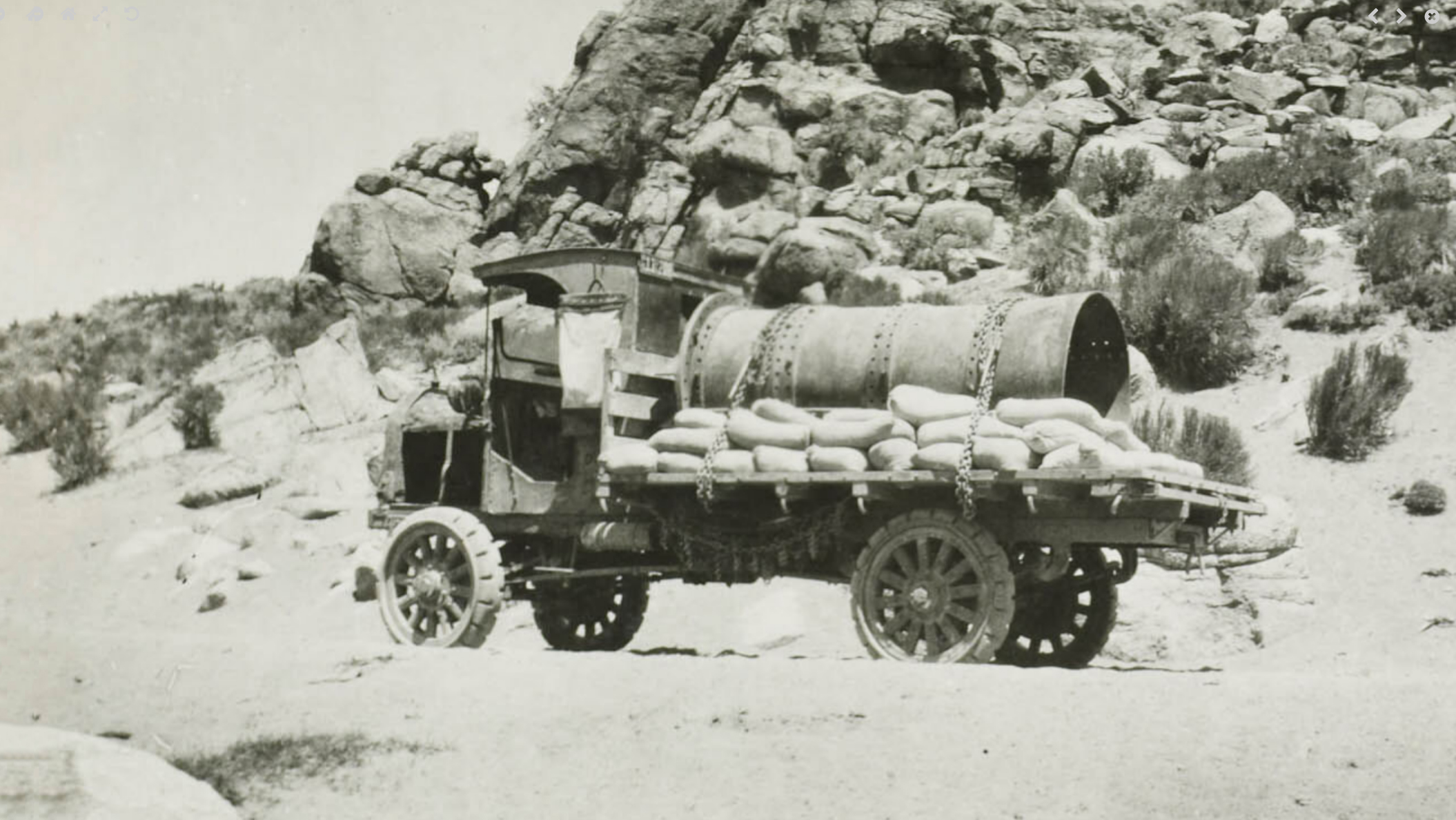
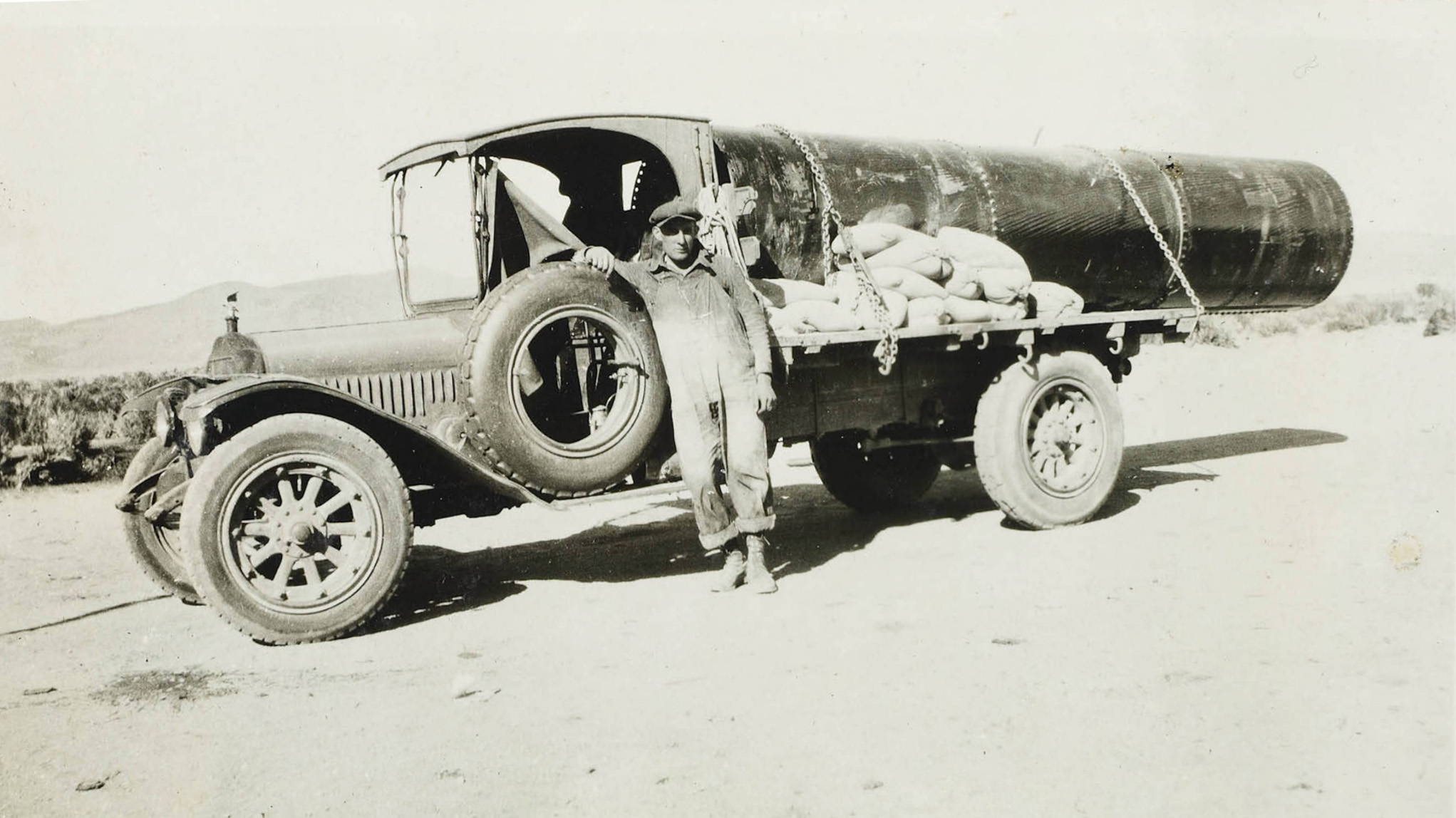 Trucker on his way to Mono Lake with a load of cement and steel pipe |
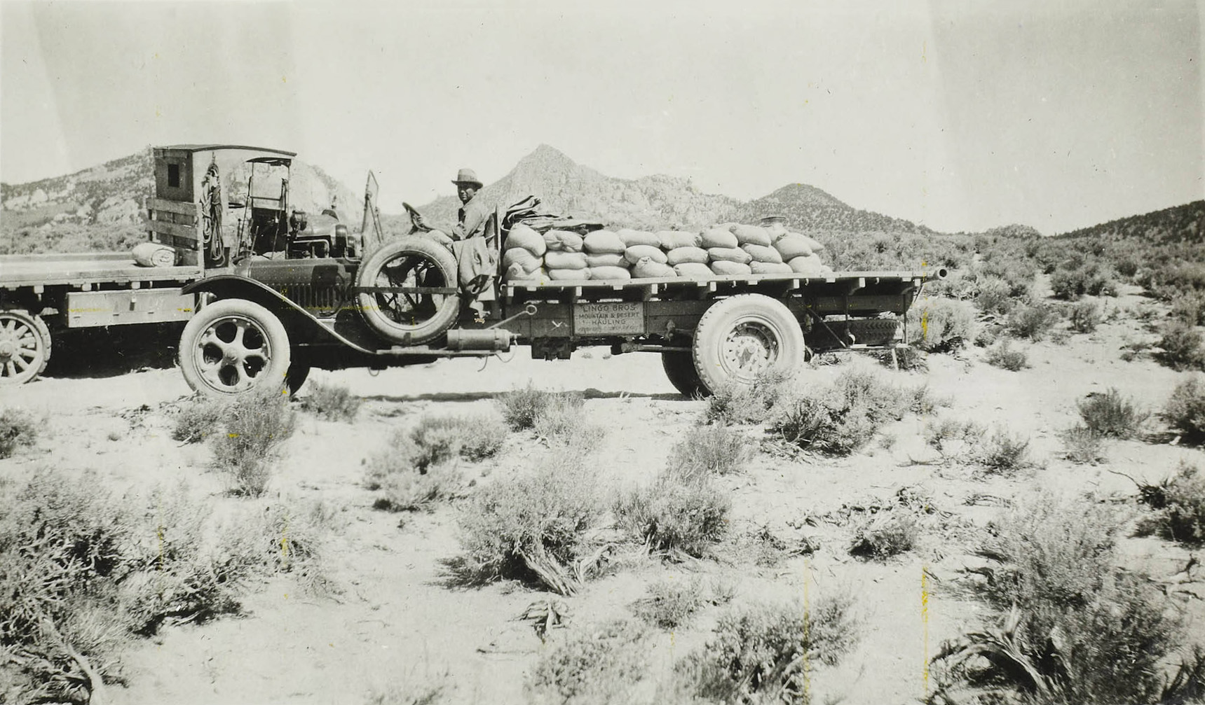 Lingo Brothers Mountain & Desert flatbed truck with a load of cement |
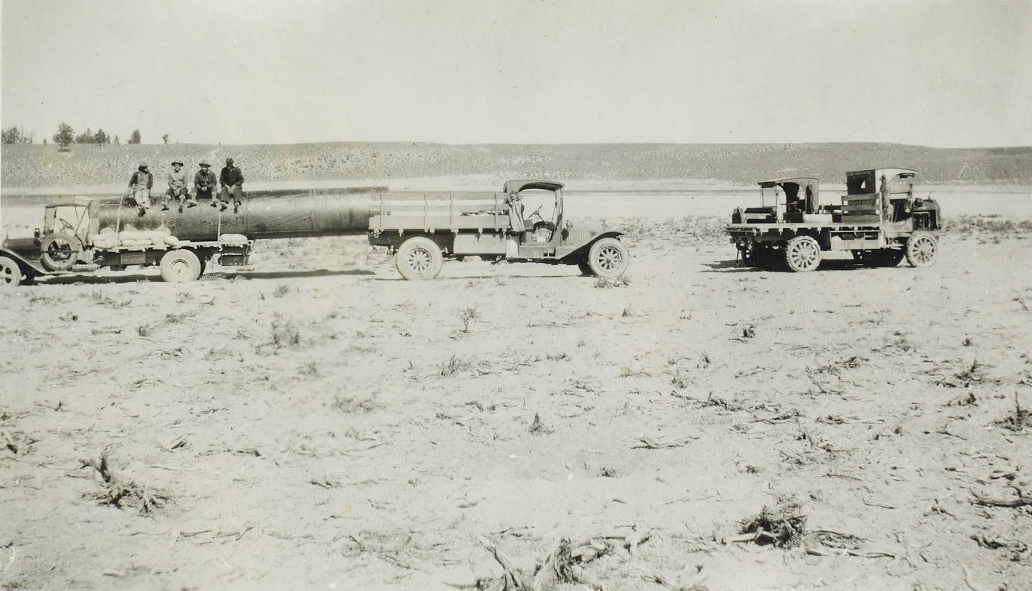 Trucker on his way to Mono Lake with a load of cement and steel pipe |
|
 Loading up with a truckload of cement |
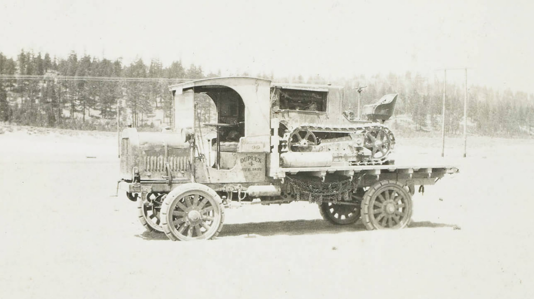 Duplex truck with a tractor loaded on the back |
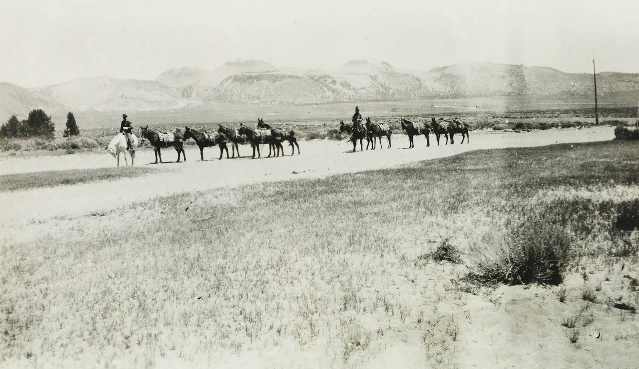 Two packers with their strings of mules near Mono Lake |
|
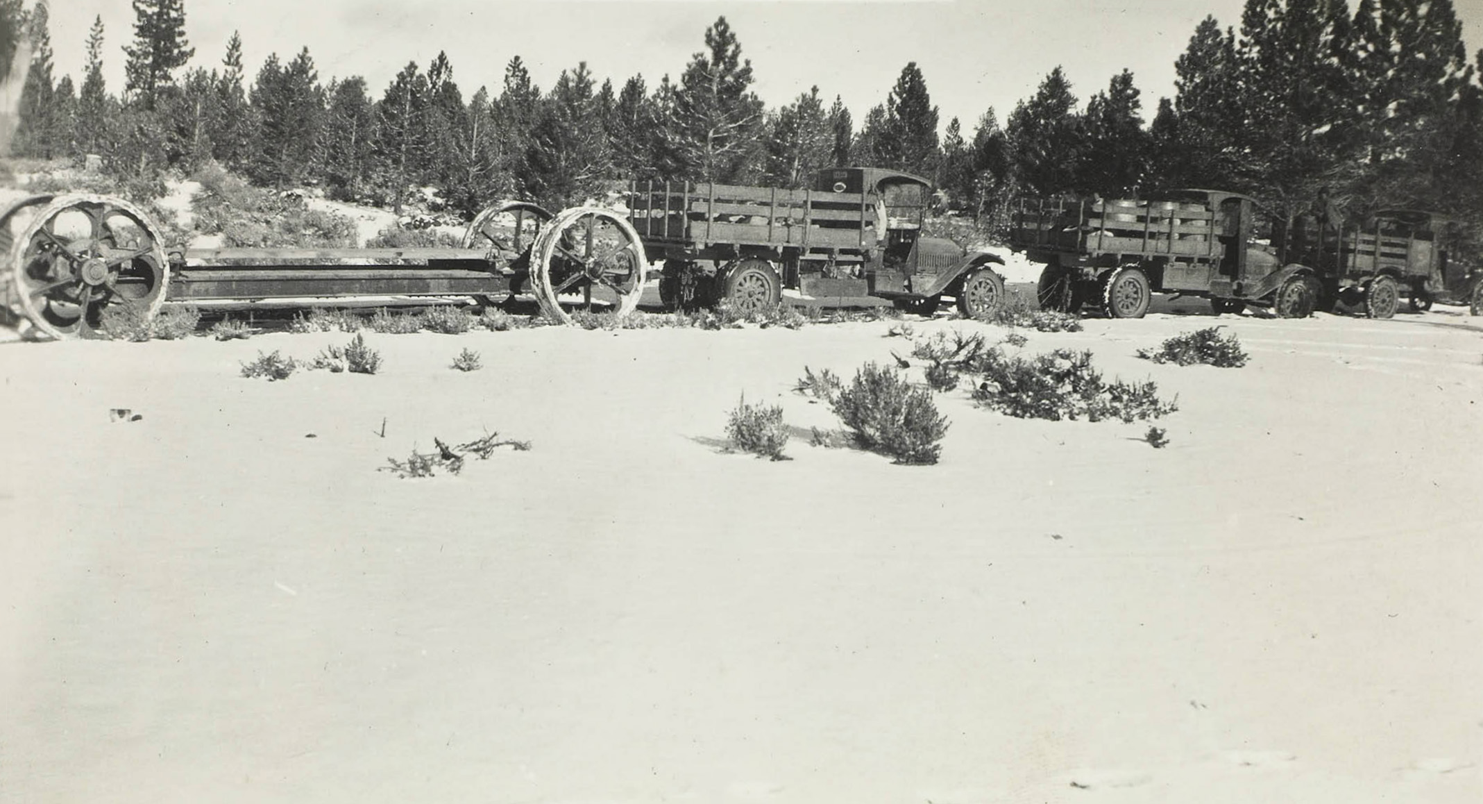 Transformer sled and trucks |
|
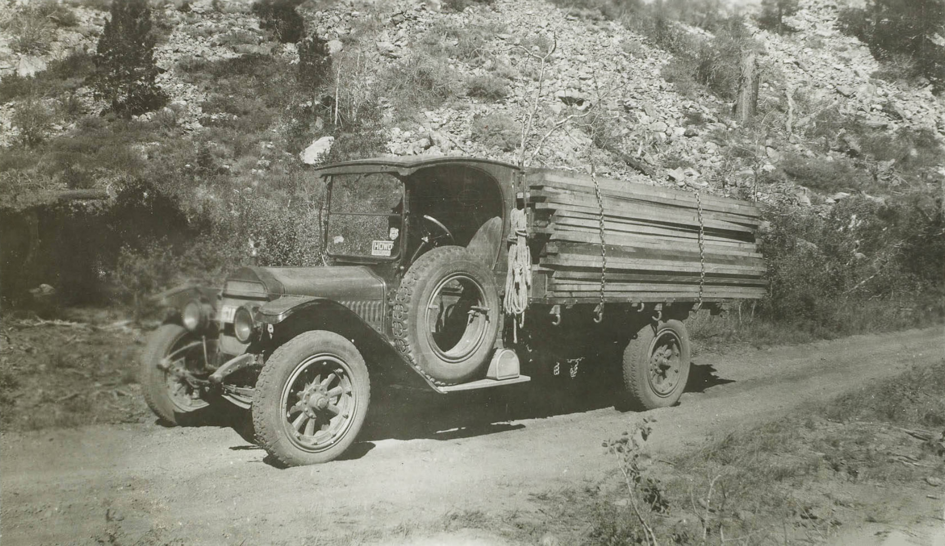 Truck with a load of lumber |
 Group of men working on a makeshift road |
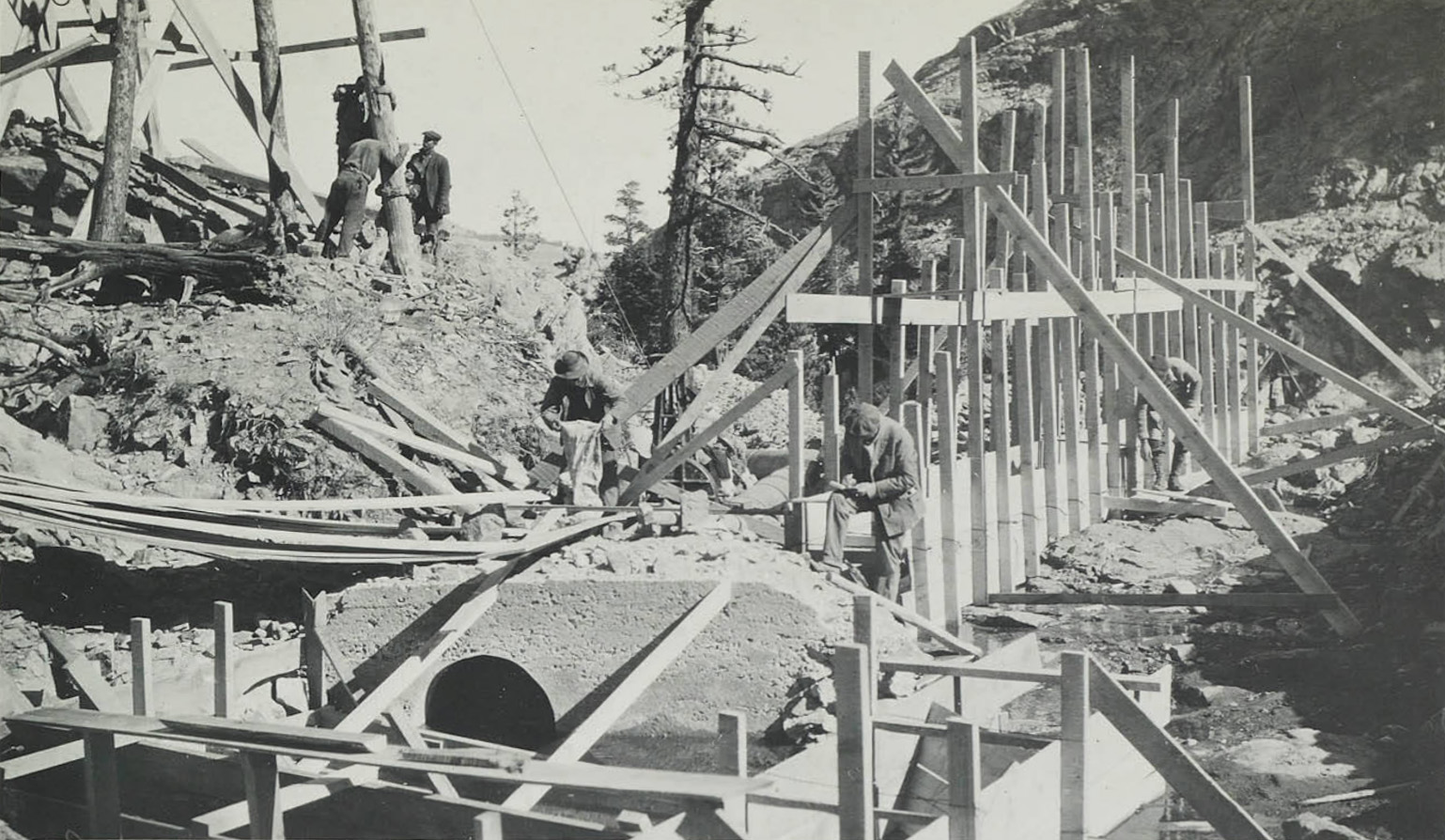
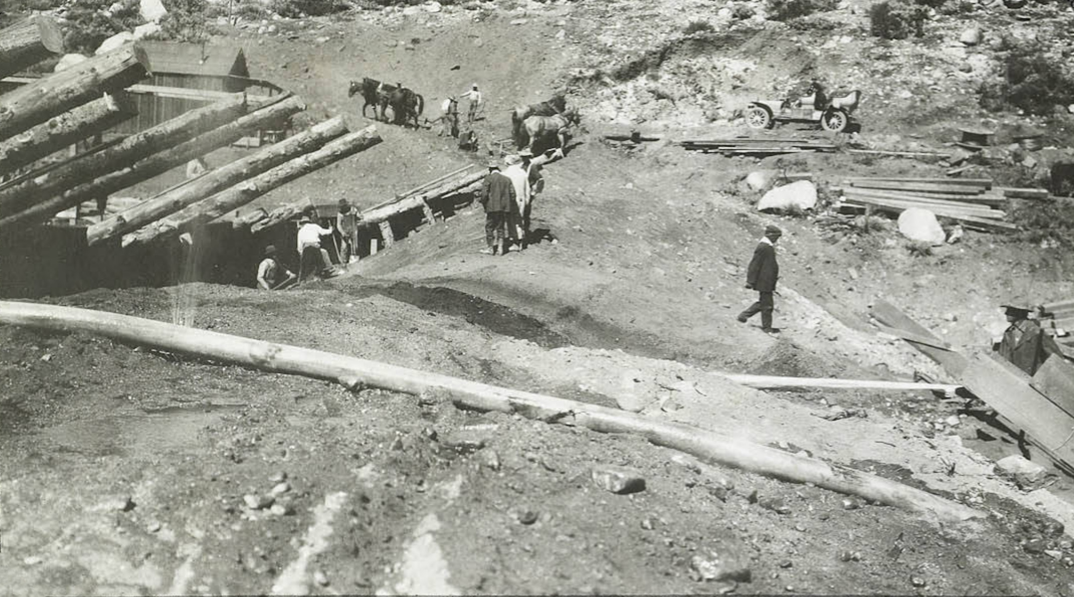
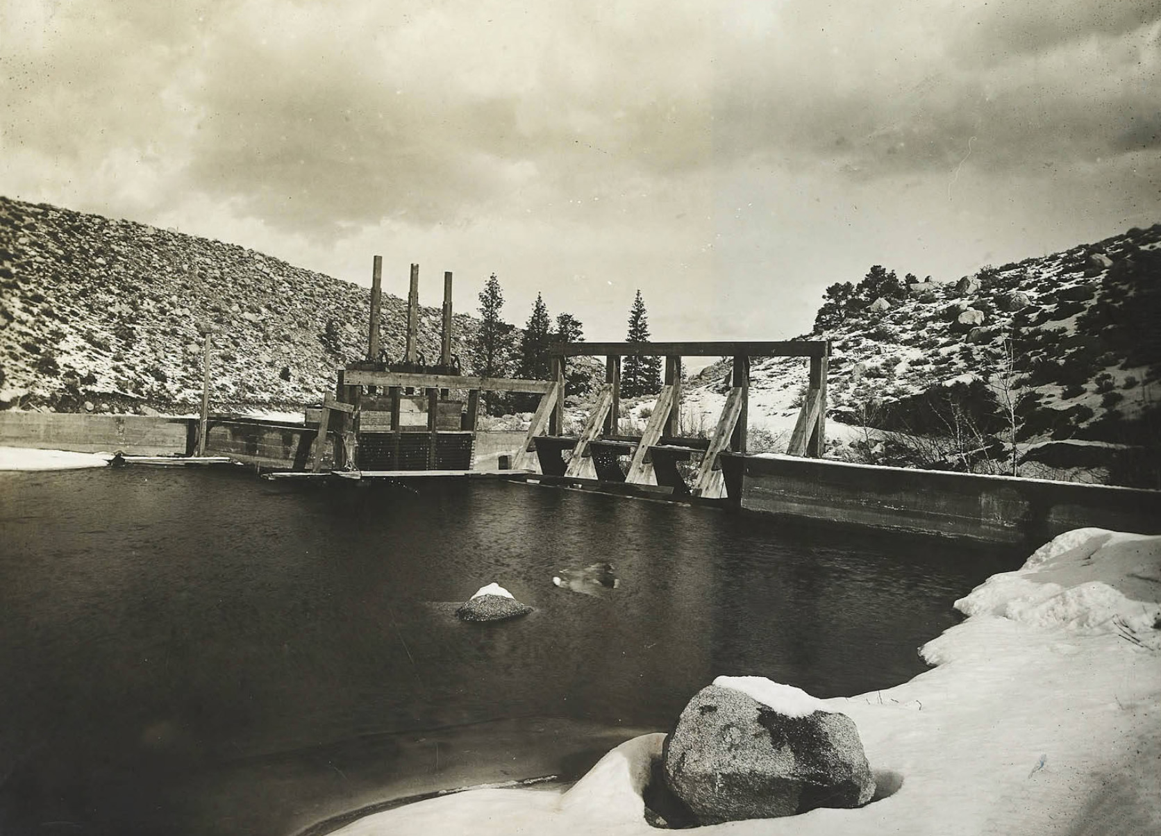
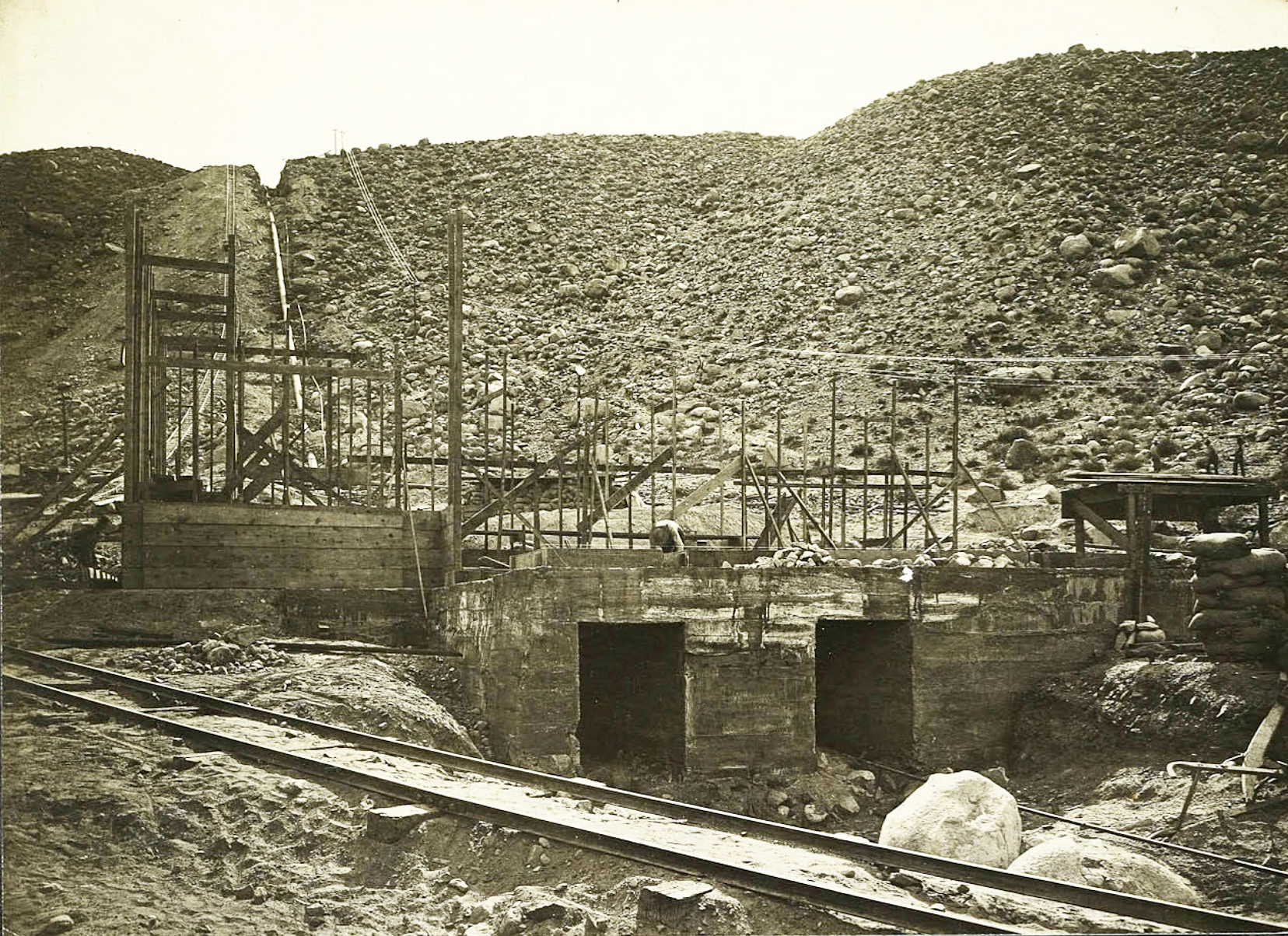
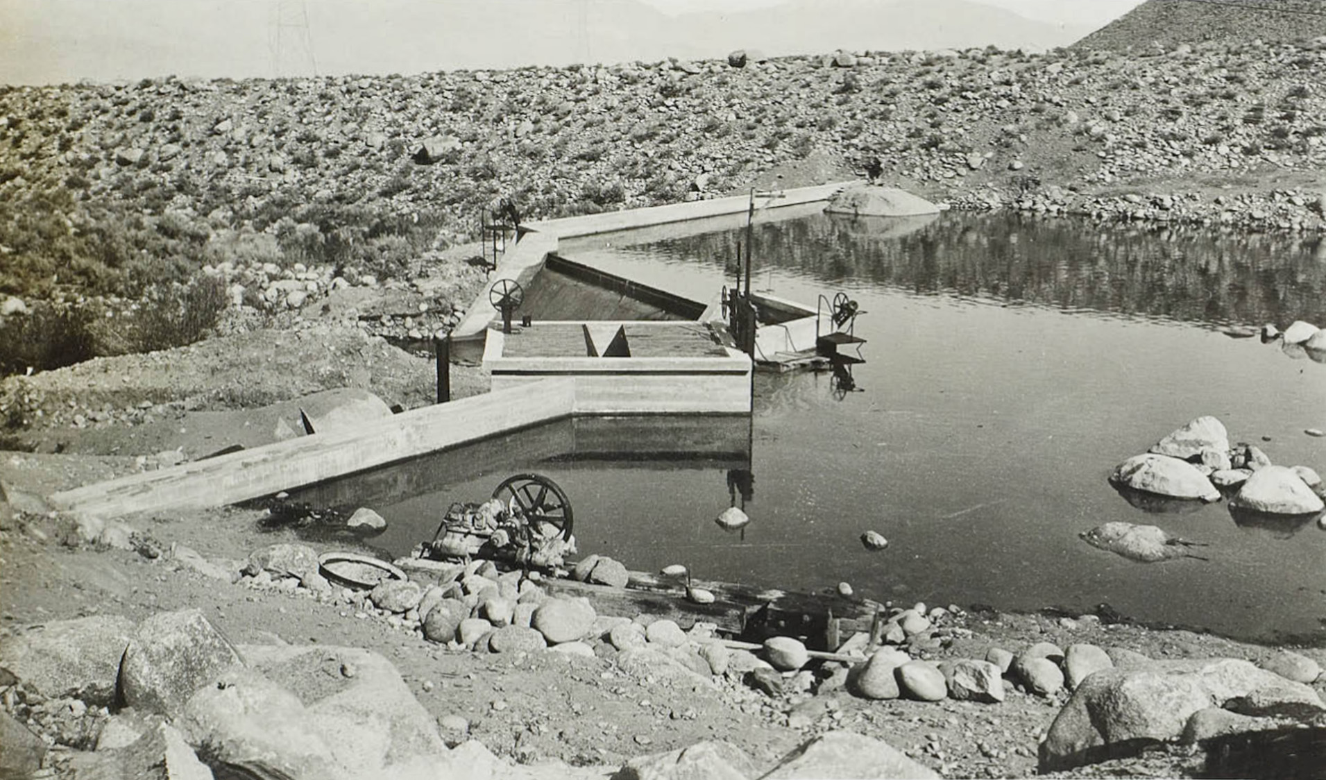
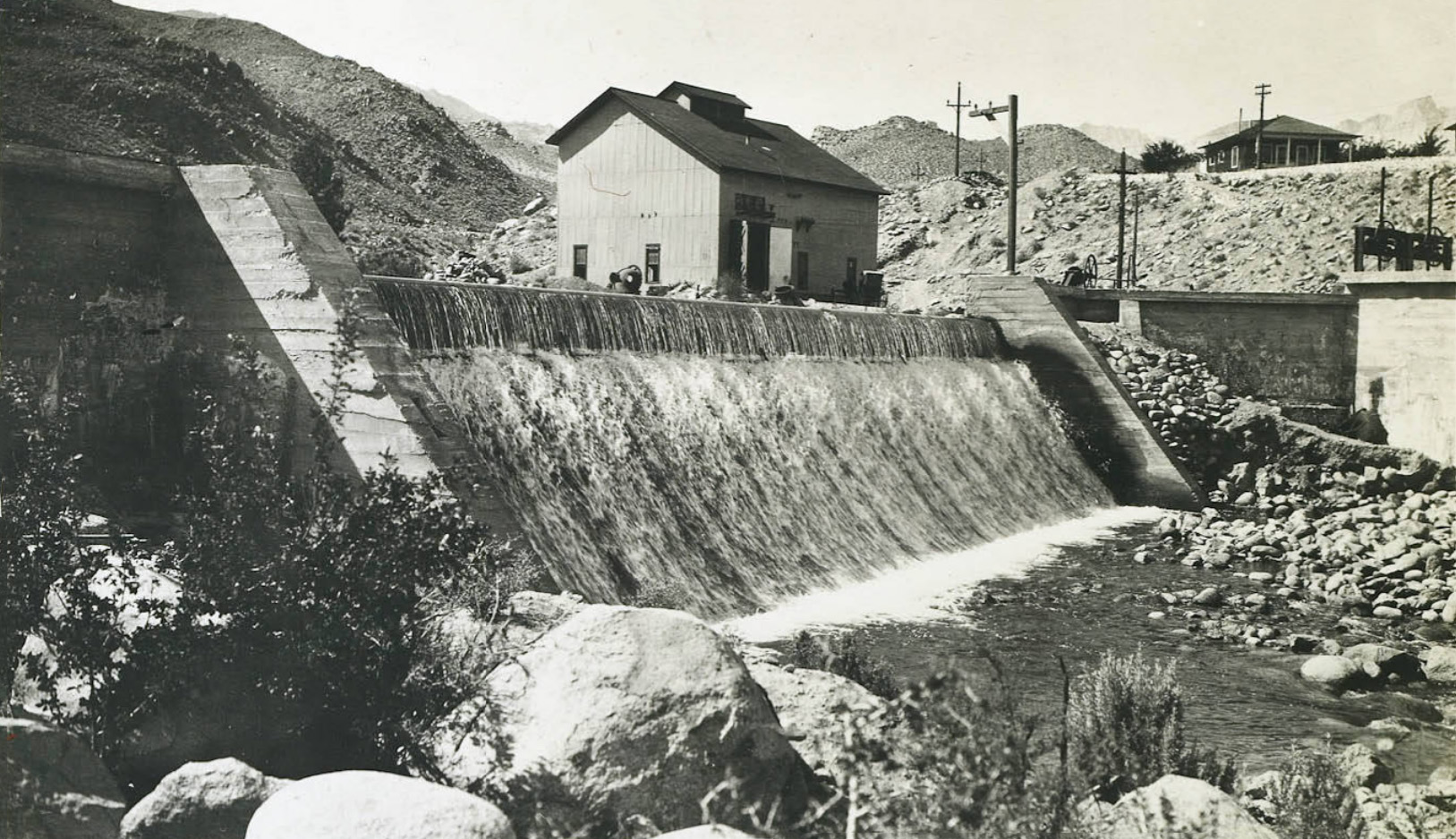
 Men working on intake dam |
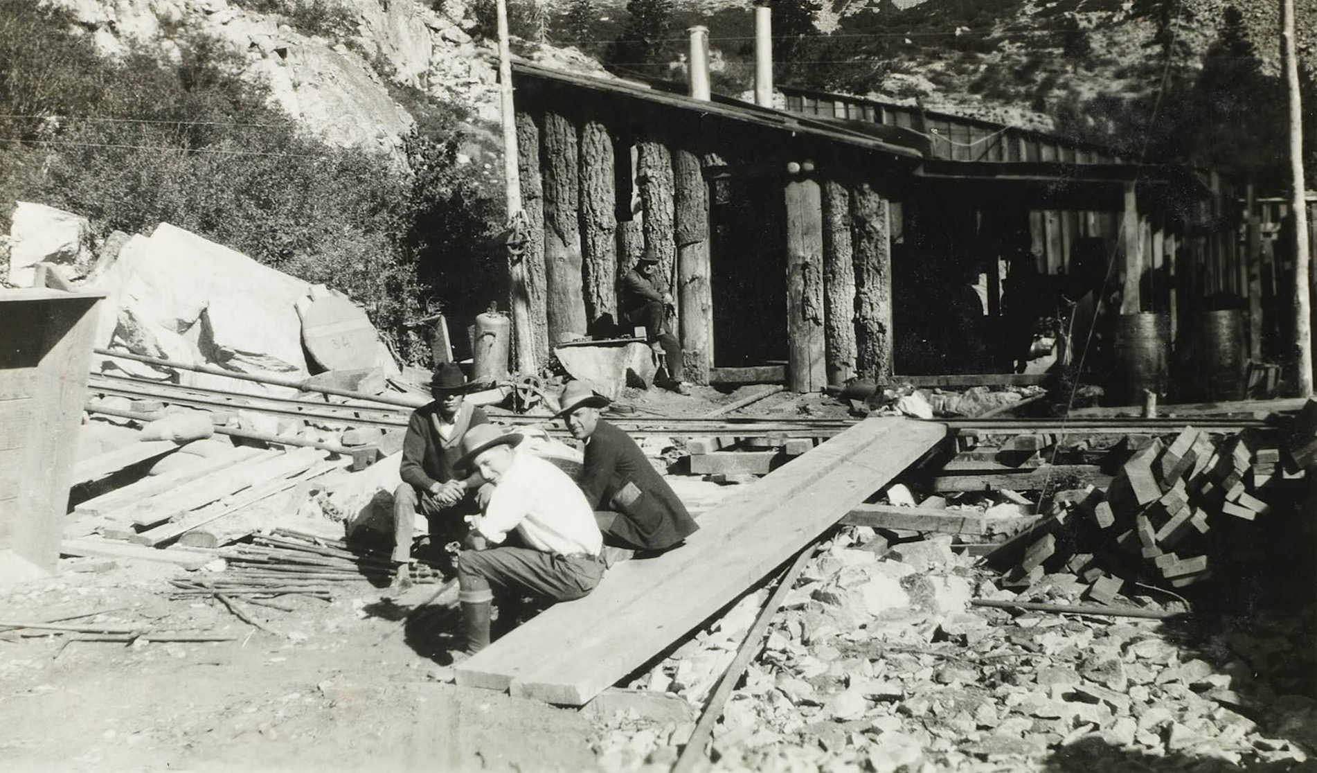
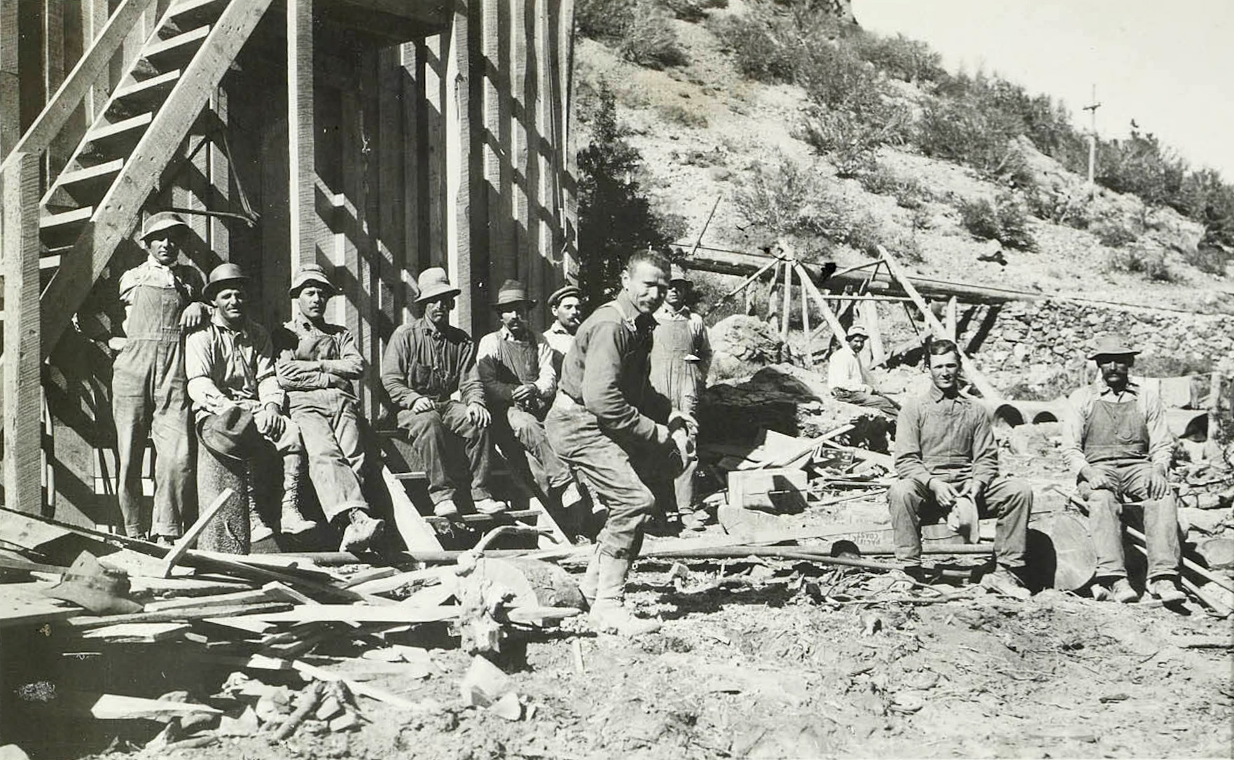
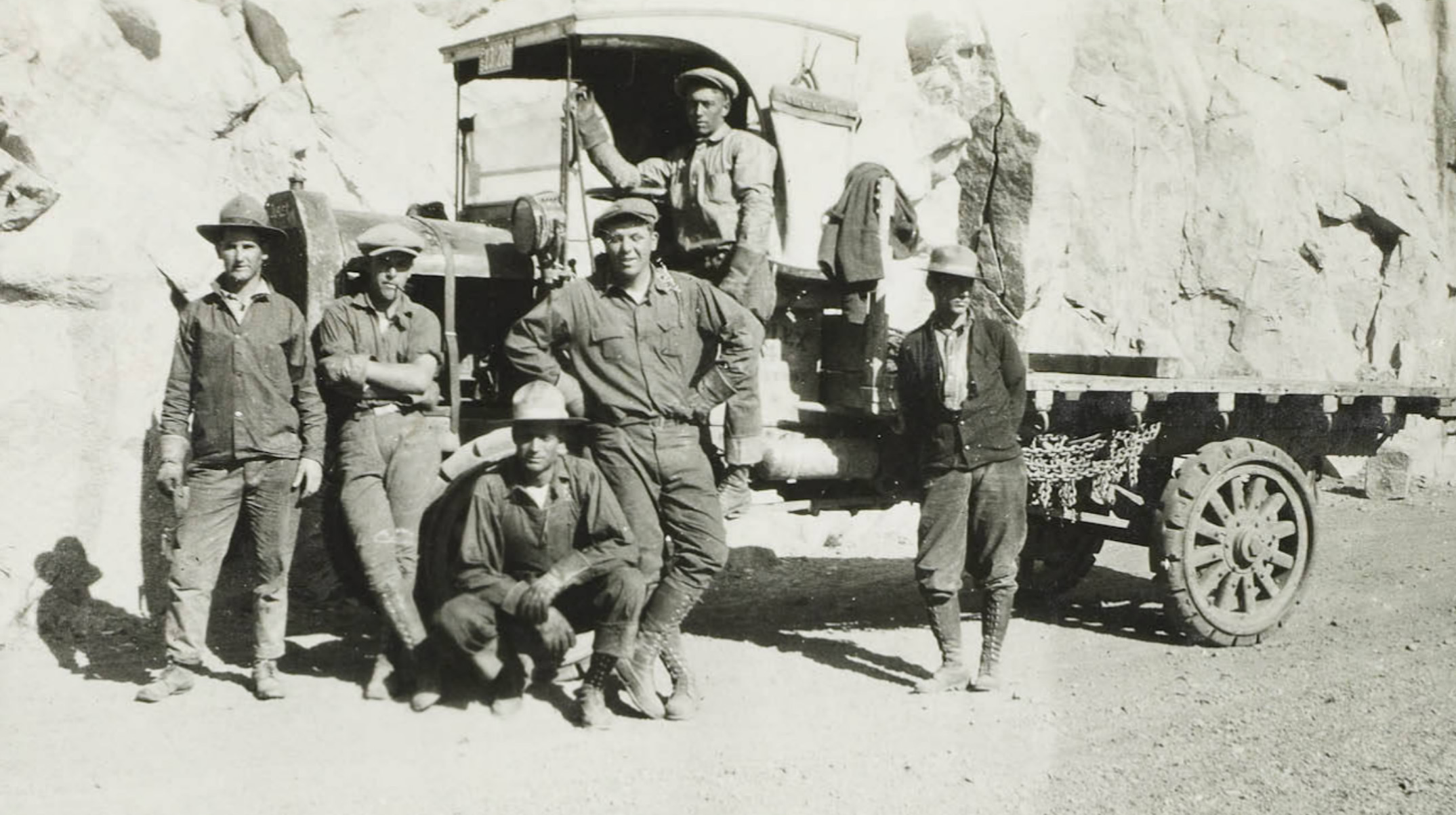 Construction workers taking a break |
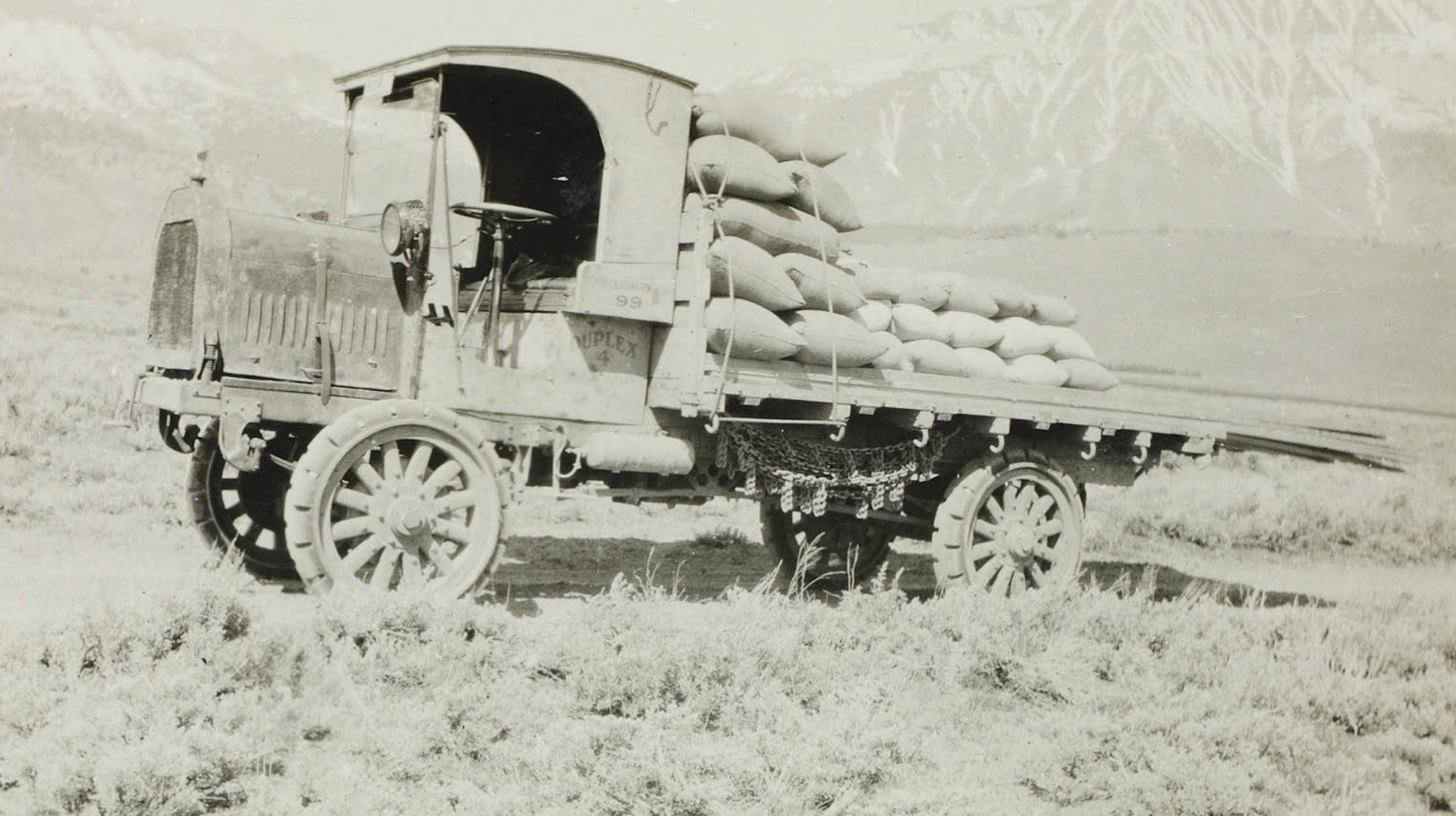 Duplex truck with a load of cement |
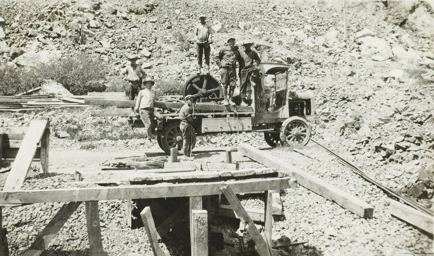
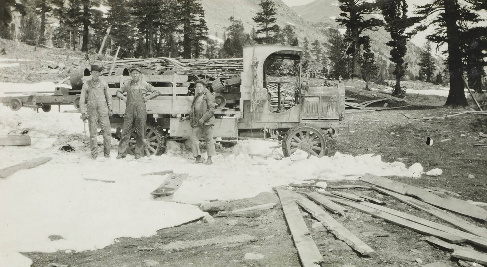 Workers taking a break from picking up wooden planks |
 Truck on it's way from Benton with a load of steel pipe and cement |
 Truck hauling transmission line towers |
 Truck hauling transmission line towers |
|
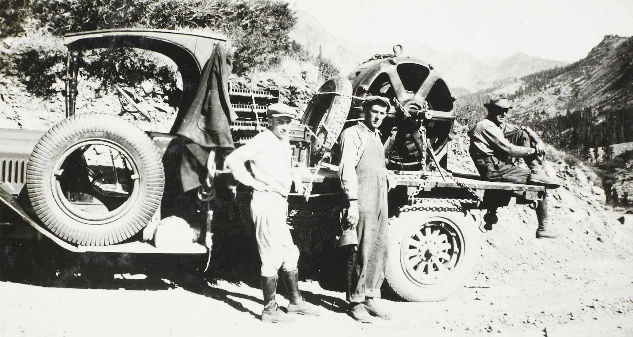
Shooting "The Golden Princess" (1923) on Bishop Creek |
|
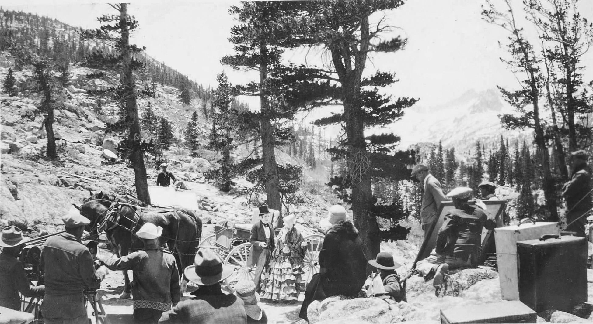 Filming the silent movie "The Golden Princess" on Bishop Creek during construction of the Bishop Creek Powerhouses |
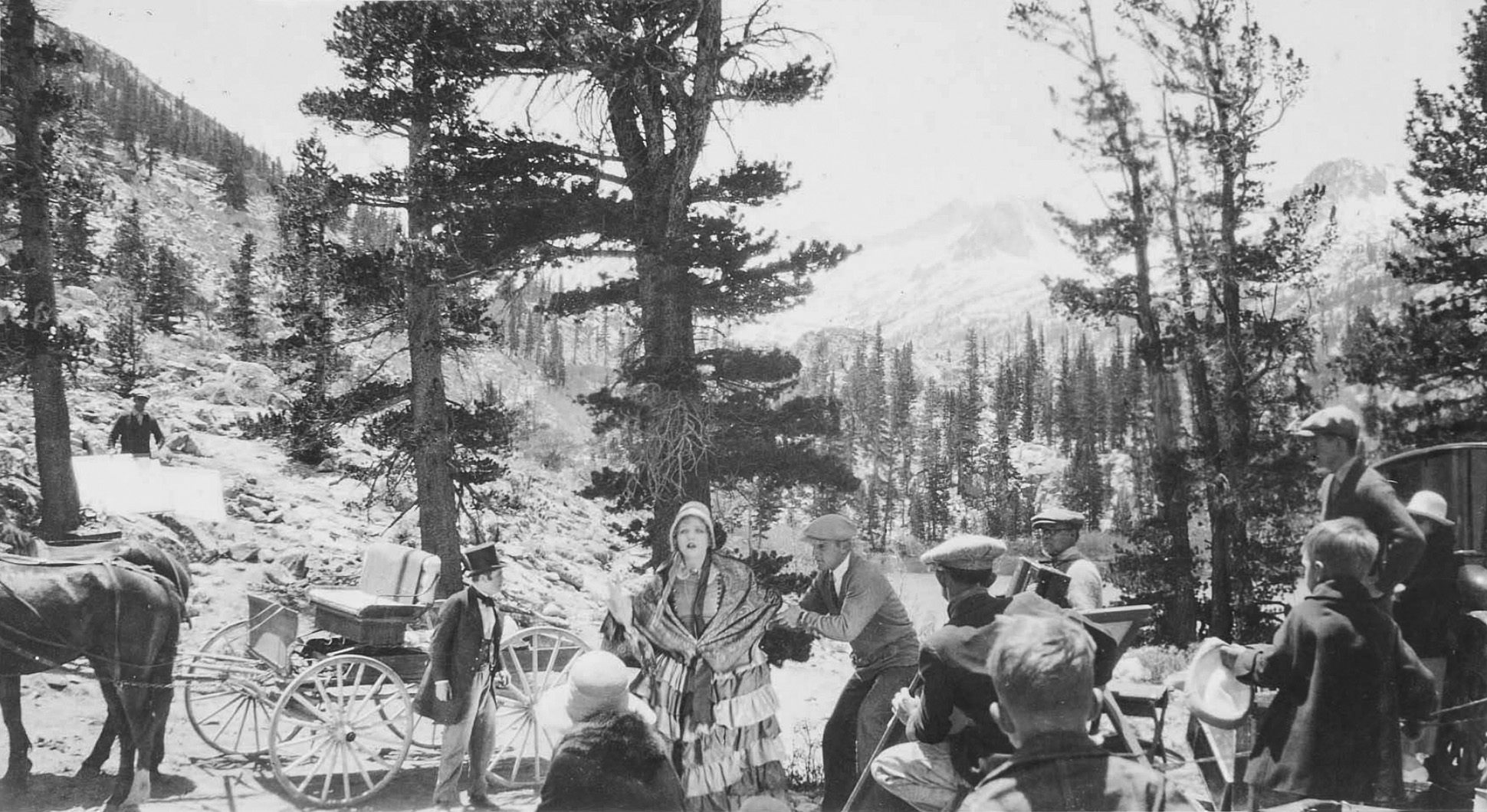 Filming the silent movie "The Golden Princess" on Bishop Creek during construction of the Bishop Creek Powerhouses |
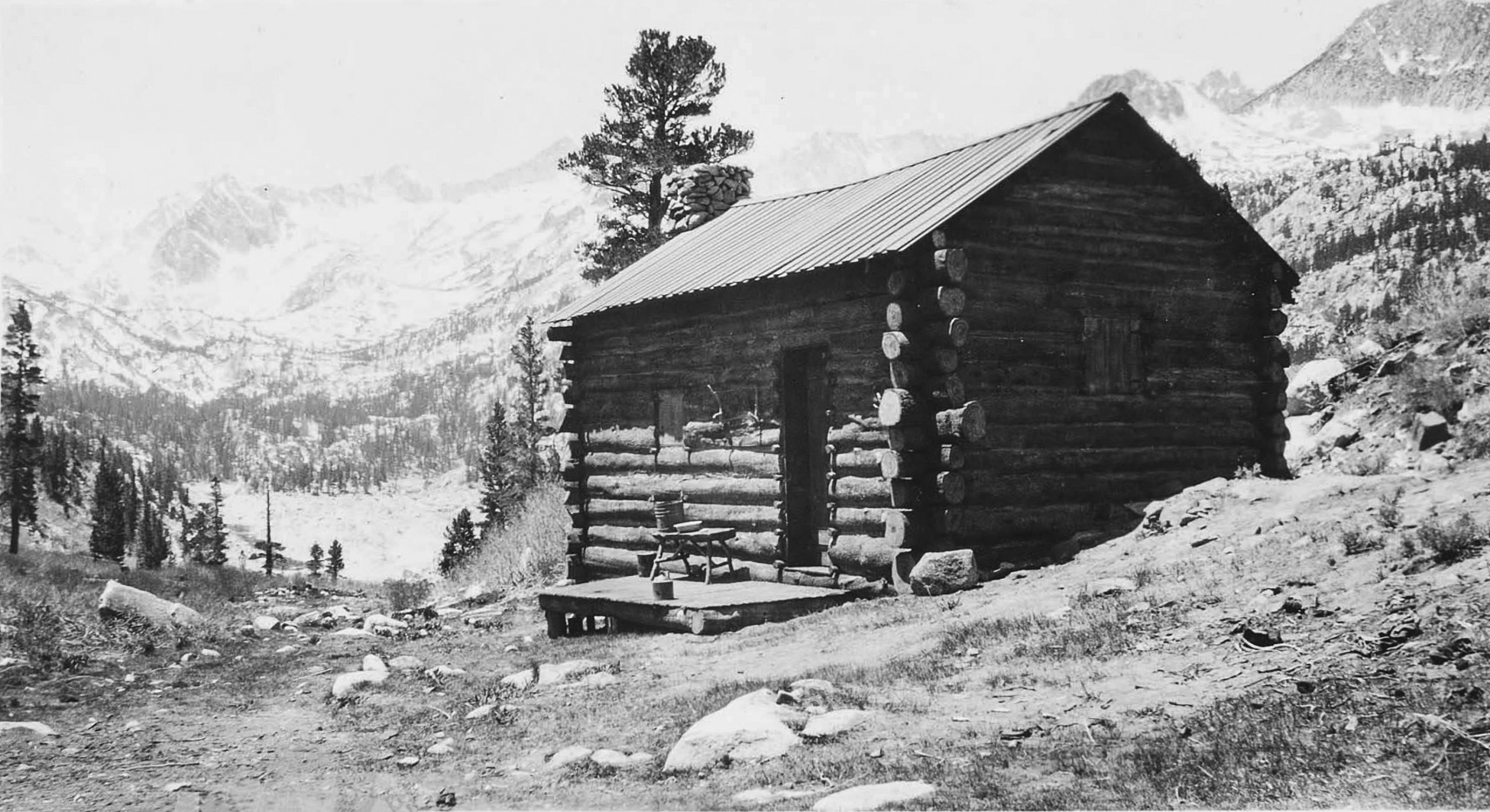 Cabin used in the movie The Golden Princess |
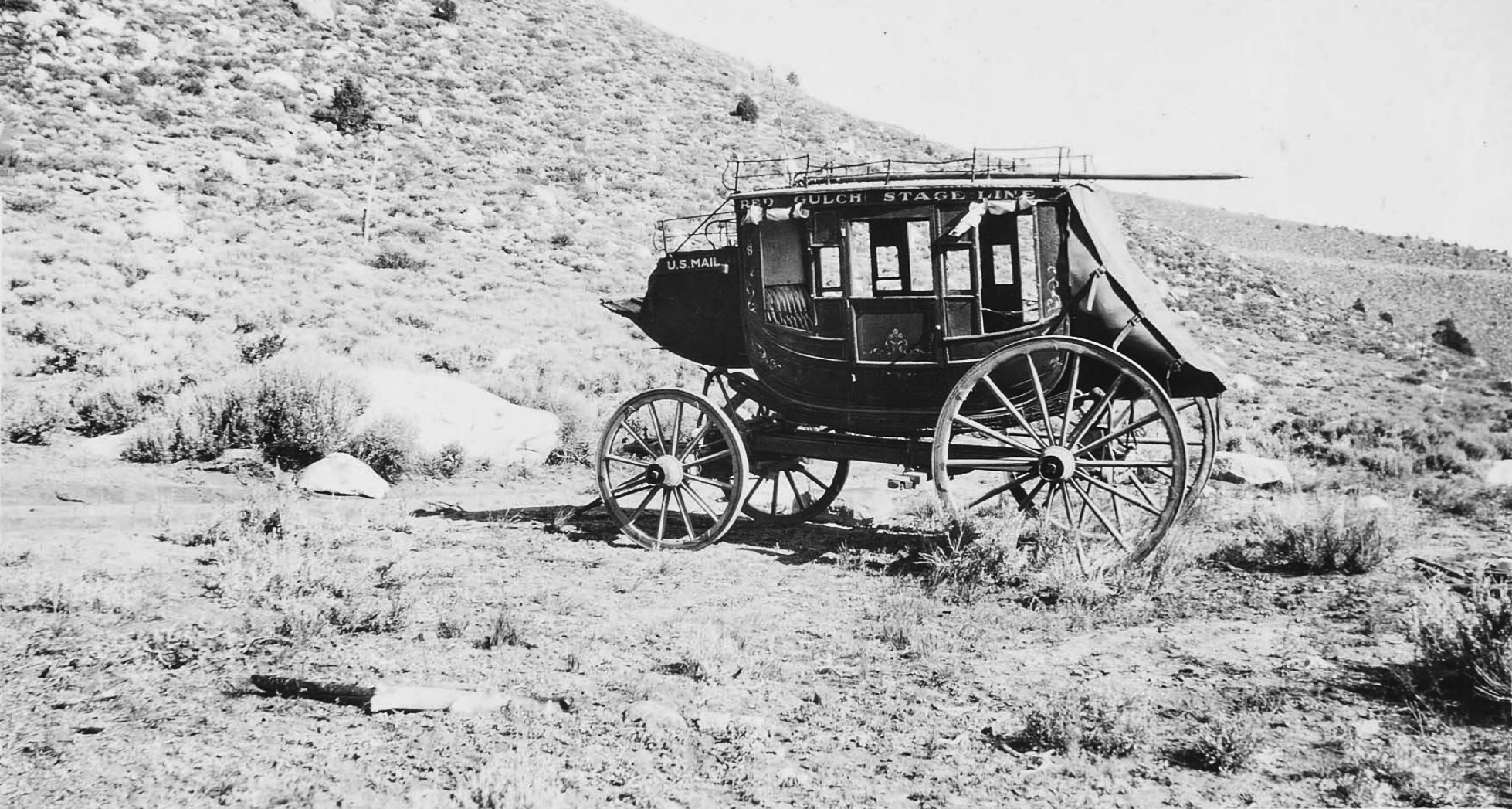 Stagecoach used in the movie The Golden Princess |
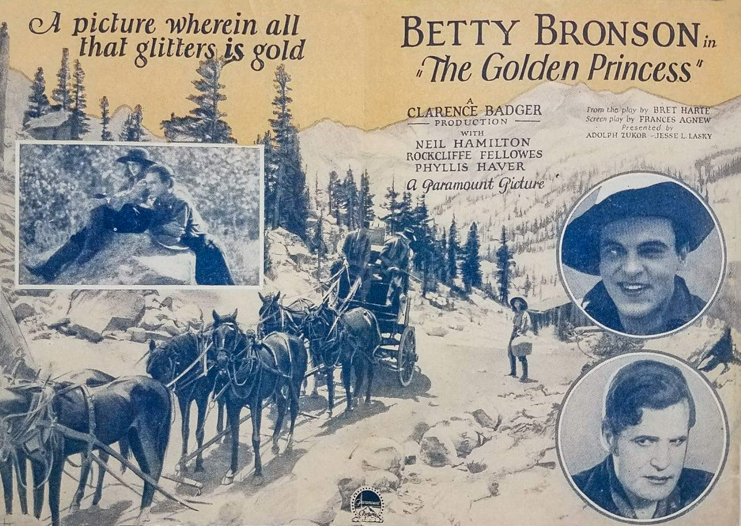 The Golden Princess (Photo courtesy of eBay) |
 The Golden Princess (Photo Internet Movie Database) |
Bishop Creek Powerhouse No. 1 The Powerhouse that Never was Built |
|
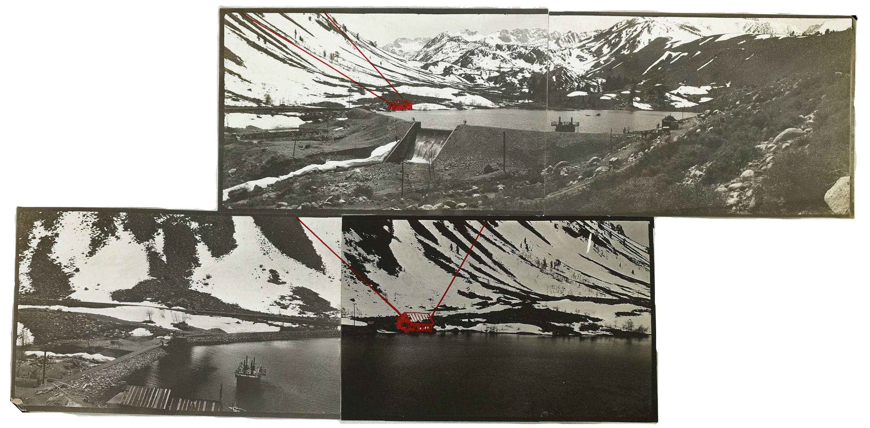 Equalizing Reservoir showing proposed location of Plant No. 1 |
|
 Equalizing Reservoir - proposed Plant 1 |
 Equalizing Reservoir - proposed Plant 1 |
 South Lake Dam construction - September 1910 |
 South Lake Dam construction - September 1910 |
 South Lake Dam construction - September 1910 |
 South Lake Dam construction, putting in a new valve - September 1910 |
 South Lake Dam Intake 5 |
 South Lake Dam construction - September 1910 |
Bishop Creek Hydroelectric Facilities and Operations
by Southern California Edison
Bishop Creek Powerhouse No. 2 Lake Sabrina |
|
 Bishop Creek Plant #2 Water from Hillside and No 1 Reservoirs flows down the natural stream bed to Intake No.2, a balancing reservoir for operation of the Bishop Creek Plants. From Intake No. 2, the water is supplied to Bishop Creek Plant #2 through 10,035' of Redwood stave pipe and 2,646' of 48" steel pressure pipe. Five power plants harnessed in tandem, utilize consecutively the waters of Bishop Creek throughconnecting pipe lines and generate an aggregate of 43,520 horsepower, developed under a combined head of 3,555'. The water is then returned, undiminished, to the stream bed at the mouth of the canyon for irrigation. |
 Interior Powerhouse #1 (Plant 2) |
 Bishop Creek Plant #2 - Powerhouse |
 Bishop Creek Plant #2 - Transformer House |
 General View Bishop Creek Plant #2 |
 Interior Powerhouse #1 (Plant 2) |
 Interior Plant #2 |
 Bishop Creek Plant #2 from the Terrace |
 Interior Plant #2 showing two of the 2000 K.W. Generators |
 Interiorview of the transformer house at Plant 2. Showing part of the 7,000 K.W. step-up transformers. |
 Bishop Creek Plant #2 |
 On the road to the Bishop Creek Plants |
 Bishop Creek Plant #2 |
 Bishop Creek Mess Hall and Bunk House |
 Bishop Creek Intake for Plant 3 |
 Bishop Creek Plant #2 and Intake for Plant 3 |
 Lake Sabrina Dam |
 Lake Sabrina |
 Hauling cement |
 Cooks camp near Lake Sabrina |
 Lake Sabrina Dam (Photo and text courtest Library of Congress) |
 Lake Sabrina Dam (Photo and text courtest Library of Congress) |
 Lake Sabrina Dam (Photo and text courtest Library of Congress) |
 Lake Sabrina Dam (Photo and text courtest Library of Congress) |
 Lake Sabrina Dam (Photo and text courtest Library of Congress) |
 Lake Sabrina Dam construction |
 Hillside Water Company - Lake Sabrina Reservoir/Dam - 1910 |
 Hillside Water Company - Lake Sabrina Reservoir/Dam - 1910 |
 Hillside Water Company - Lake Sabrina Reservoir/Dam - 1910 |
 Hillside Water Company - Lake Sabrina Reservoir/Dam - 1910 |
 Driving up to the Bishop Creek plants |
 Dam construction at Bishop Creek Plant 2 |
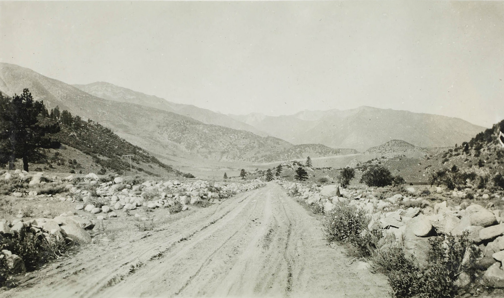
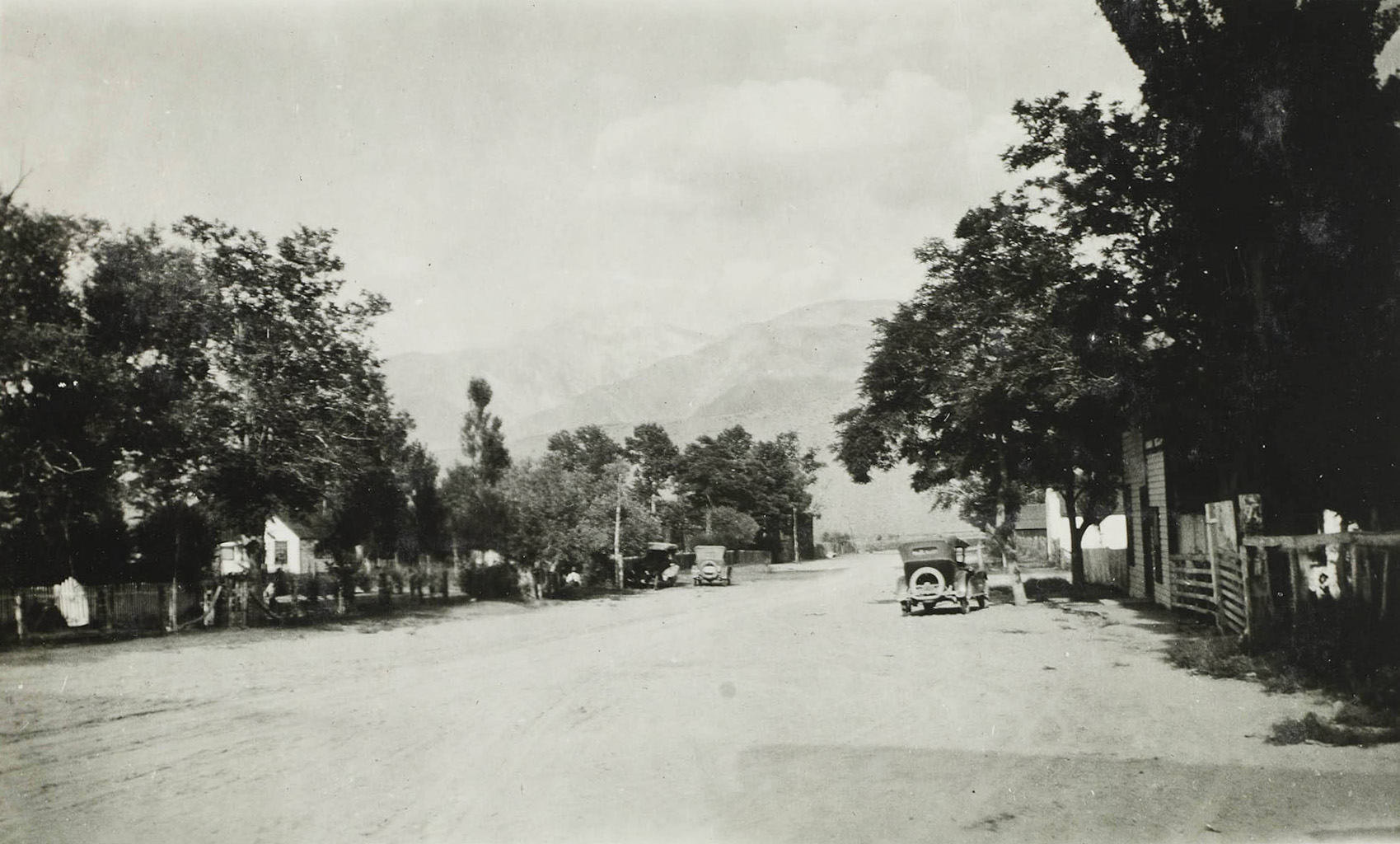
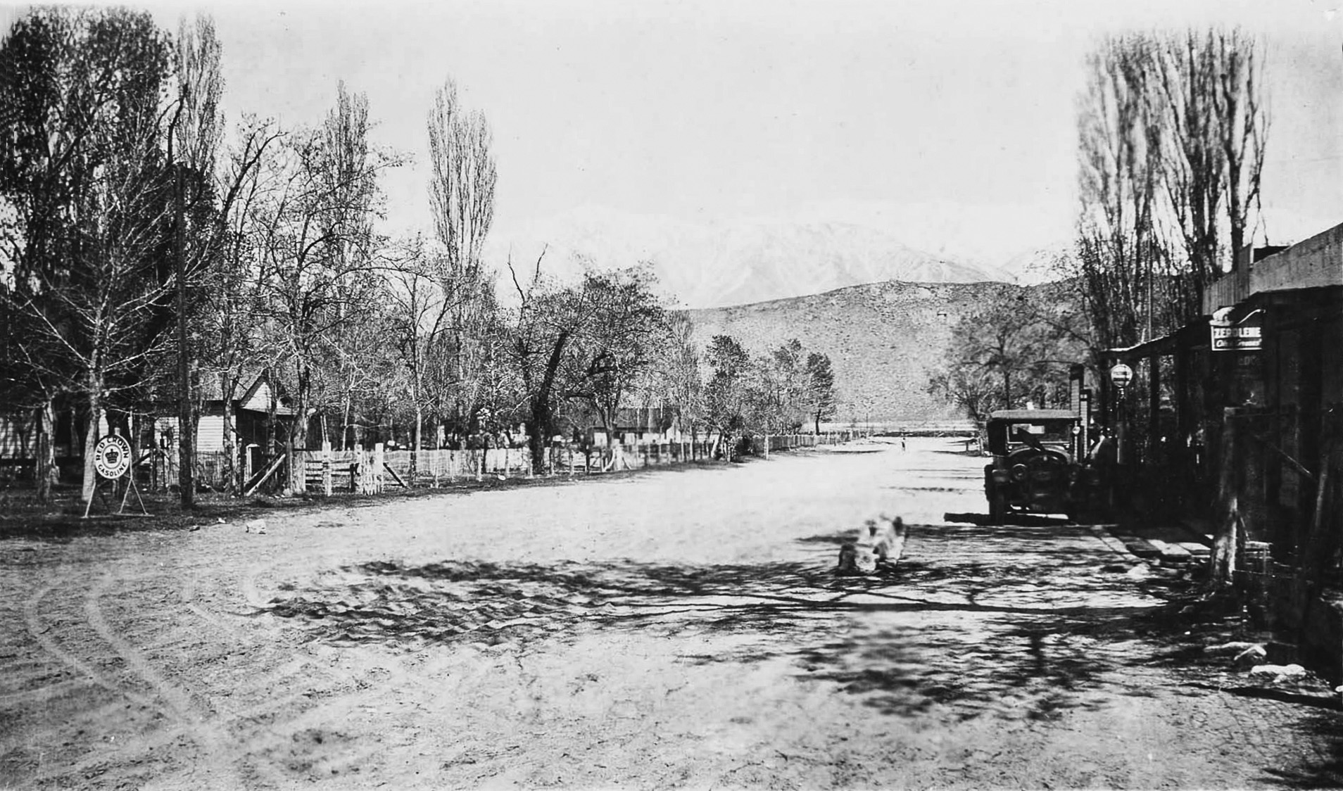
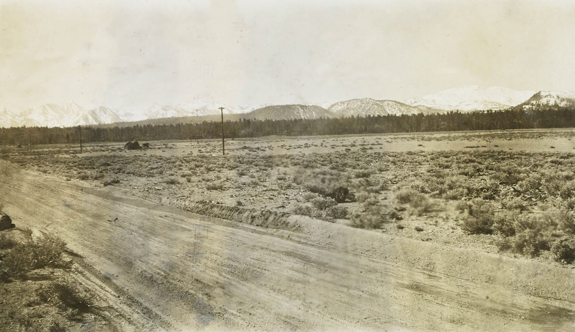 The road to Bishop - U.S. 395 |
|
 Lake Sabrina Dam construction |
 Lake Sabrina Dam construction - 1907 |
 Lake Sabrina Dam construction - 1907 |
 Regulating dam on the middle fork of Bishop Creek - 1906-07 |
 Lake Sabrina Dam construction |
 Lake Sabrina Dam construction |
 Looking at the pressure pipe line at Powerhouse #1 |
 Looking down the company's street at Powerhouse #1 |
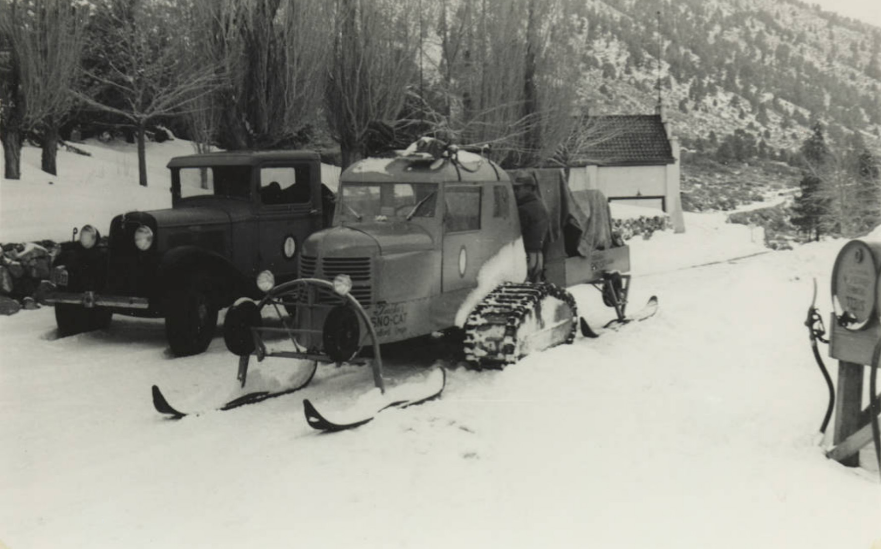
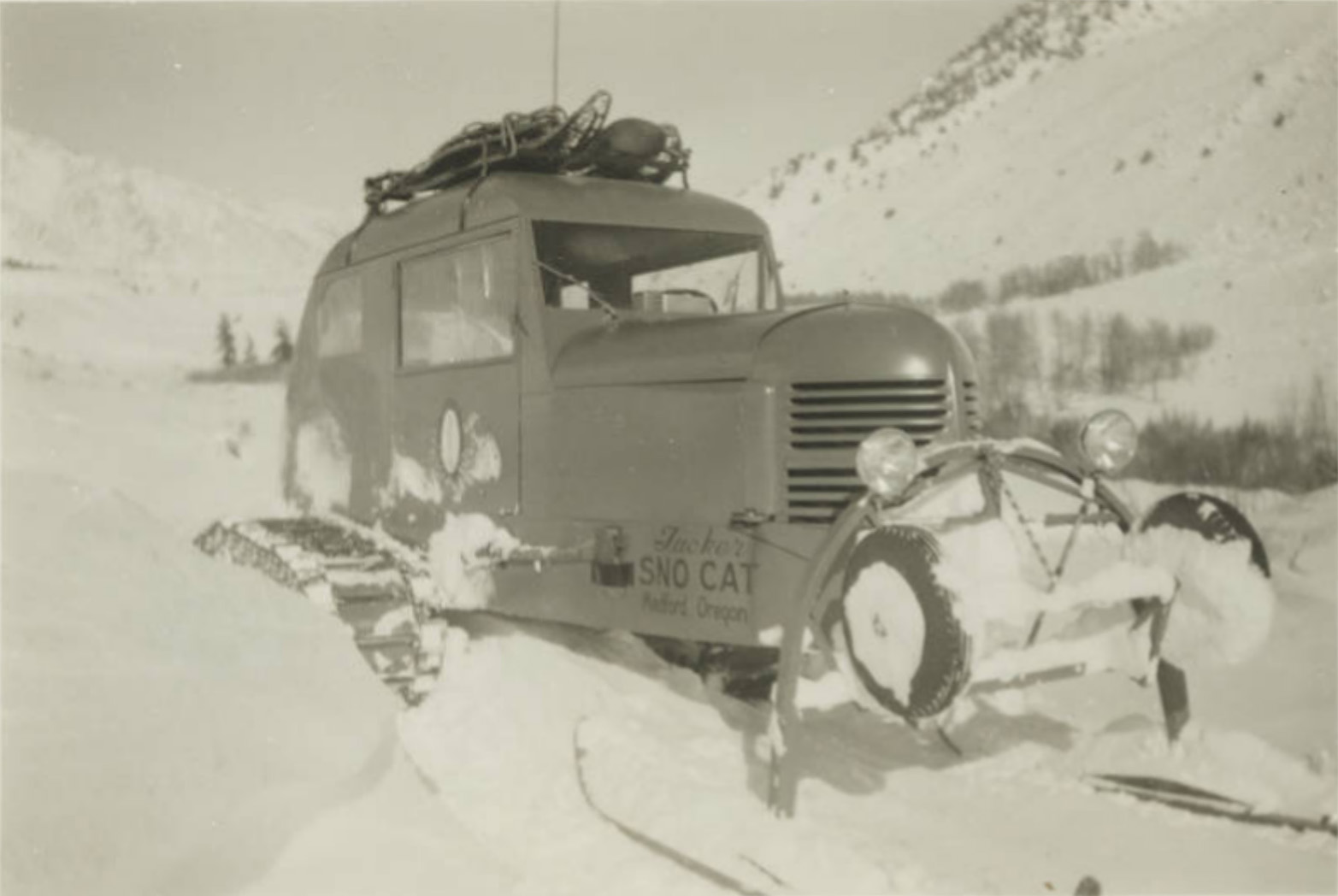 Snow-Cat in operation at South Lake |
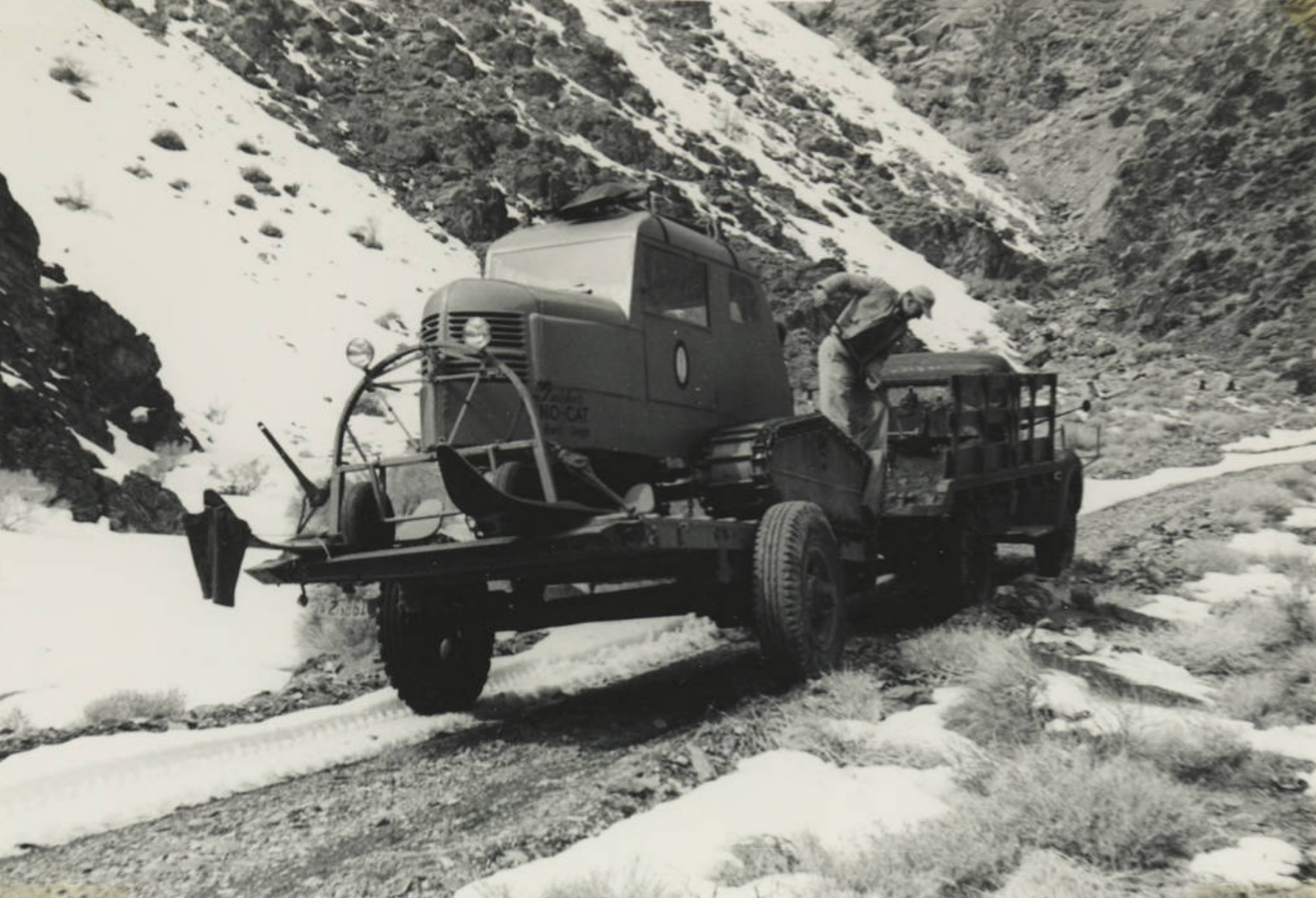 Snow-Cat Loaded for transportation to the snow area. |
 Snow-Cat in normal operation. |
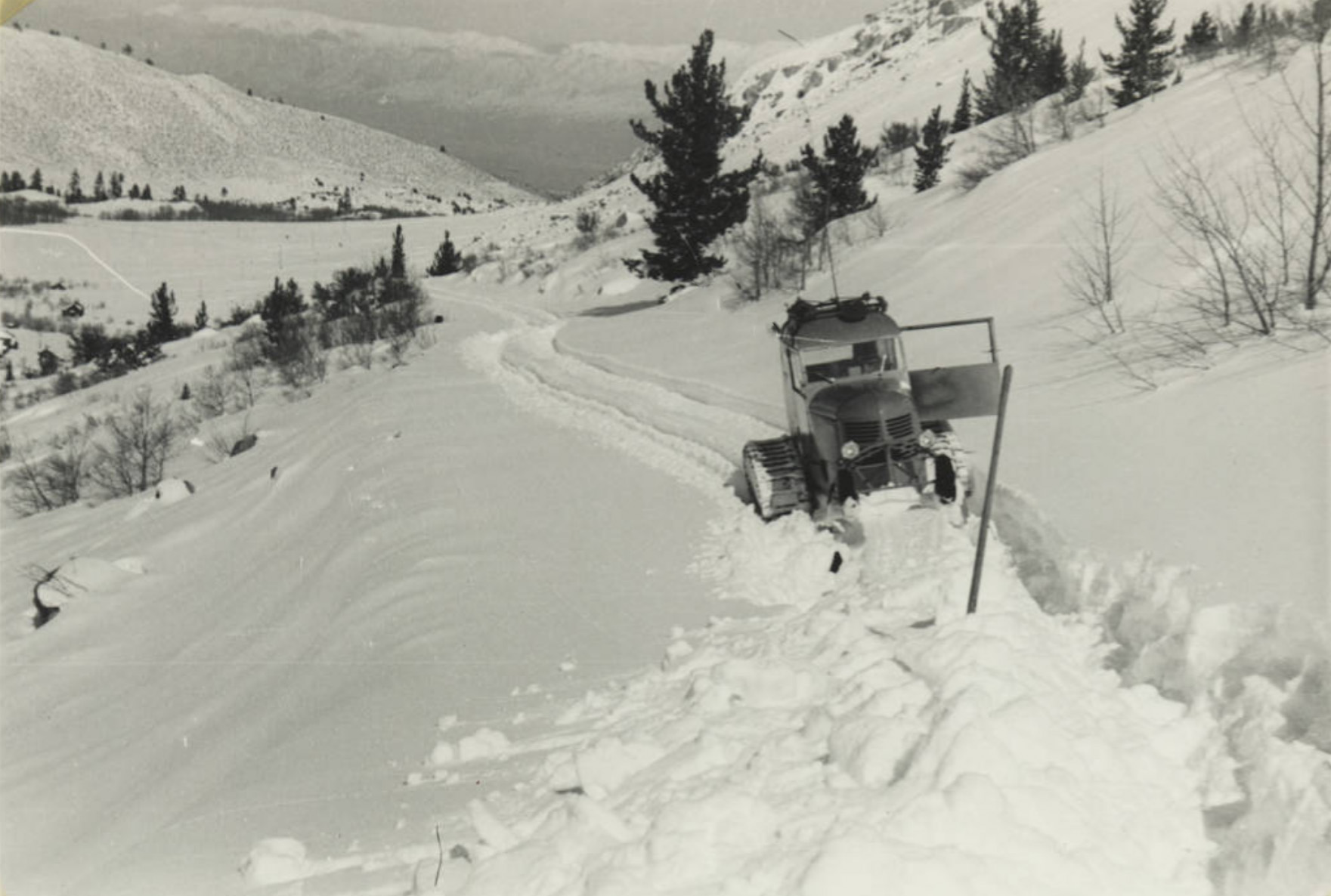 Snow-Cat Plowing a drift of snow fluffy snow. |
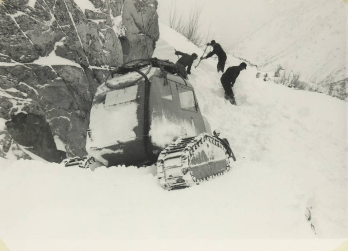 Negoating a 45 degree incline and proceeding 100 feet on a 45 degree slope - Road to Reservoir #1. Going to make emergency repairs after a tree fell on to a line cutting off power and communications. |
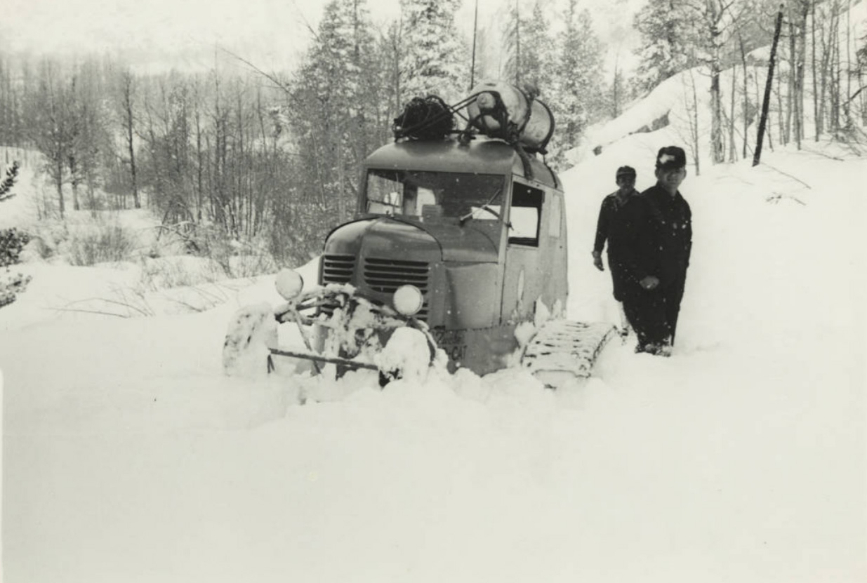 Taking an emergency "flamo" to South Lake when winter supply to keep the manometer tube from freezing was found to have leaked away. |
 Making up load at Plant 2 for Weather Tower Installation at South Lake. Approximately 1 ton load. Installation was made in one day. |
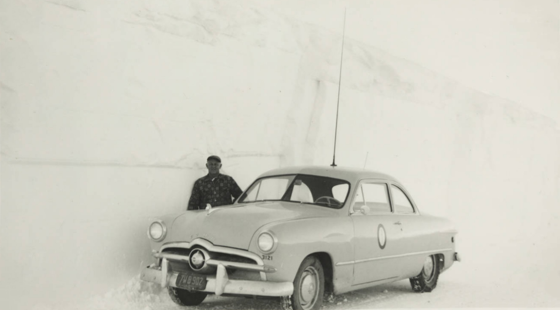 Leonard Baxter's car on U.S. 395 just north of the McGee Creek Maintenance Station - January, 1952 |
 Cottages at Bishop Creek Plant #2 |
|
Bishop Creek Powerhouse No. 3 |
|
 Bishop Creek Plant #3 From the forebay at the tail-race of Plant #2, water is supplied to Plant #3 through 13,029' of Redwood stave pipe and 4,361' of steel pressure line. The pipe lines vary in diameter from 5' to 4' at the powerhouse. This picture shows operators' cottages at the left and at the lower right the forebay and intake for Plant #4. |
 Bishop Creek Plant #3 |
 Bishop Creek Plant #3 under construction |
 Bishop Creek Plant #3 under construction |
 Powerhouse Bishop Creek Plant #3 |
 Powerhouse Bishop Creek Plant #3 |
 Powerhouse Bishop Creek Plant #3 - October 1913 |
 Worker beside steel pipe for Bishop Creek Plant #3 |
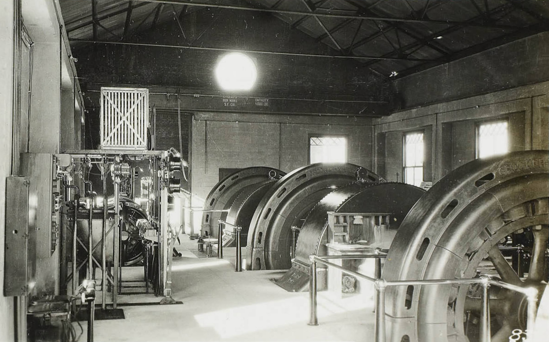
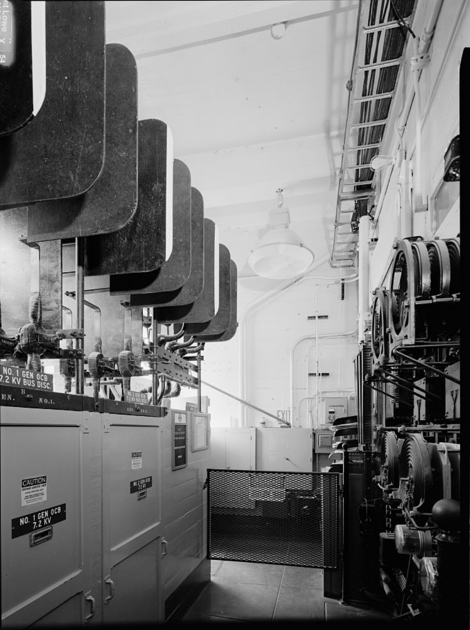
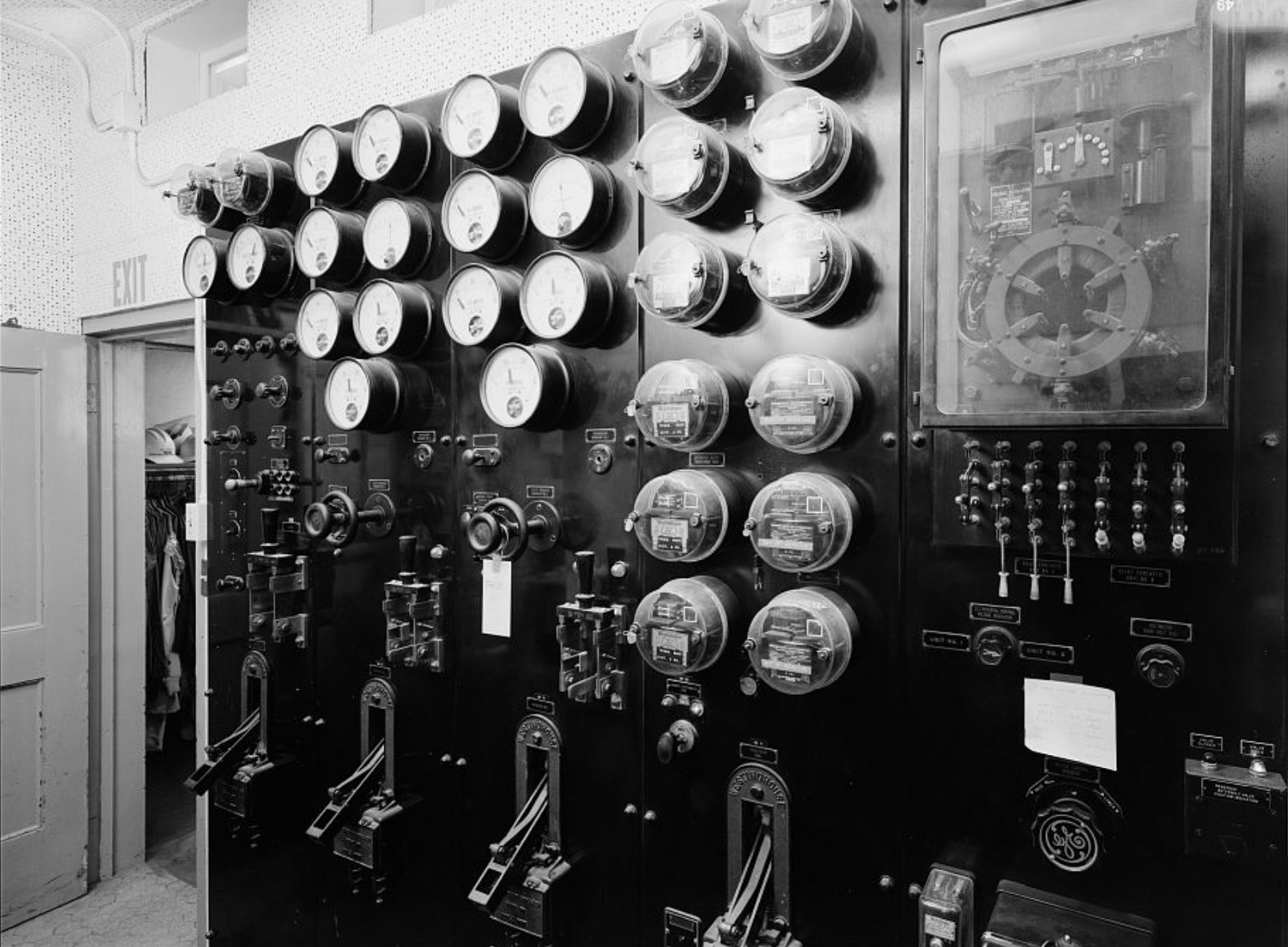
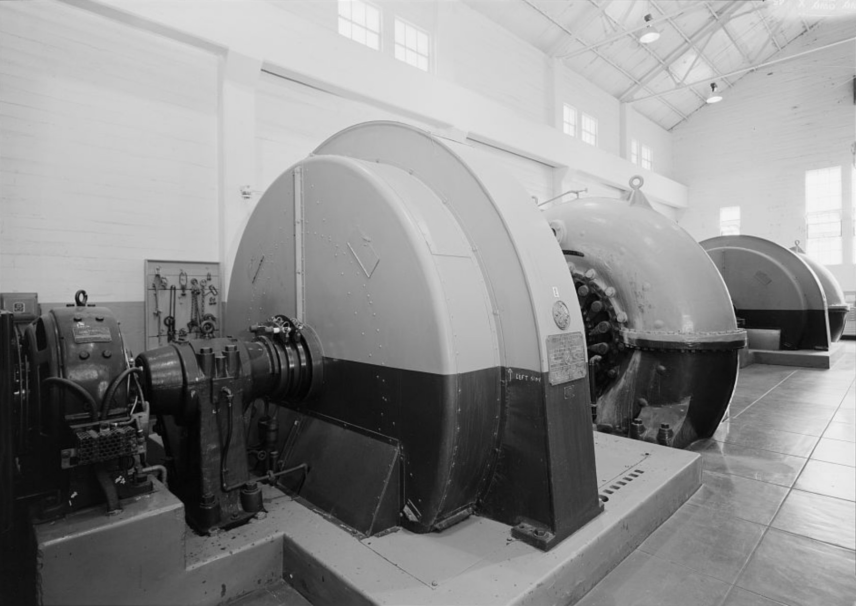
 Interior of Bishop Creek Plant #3 The generating equipment consists of three 4,000 horsepower, 300 RPM, impulse water wheelsdirect-connected to three 2,800 Kv-a, 300 RPM, 2,200 volt alternating current generators.The switchboard equipment consists of five panels complete with oil circuit breaker, instruments, rheostats, etc. The control panel for the local light and power circuits is of the safety panel type so that no live parts are accessible from the front of the panel. The panel in the right foreground of the photograph is the control panel for the motor-generator exciter set. |
|
 Interior of Bishop Creek Plant #3 showing three - 2250 K.W. Generators |
 View of the steel transmission line from Plant 3 to the Control Station on Bishop Creek. |
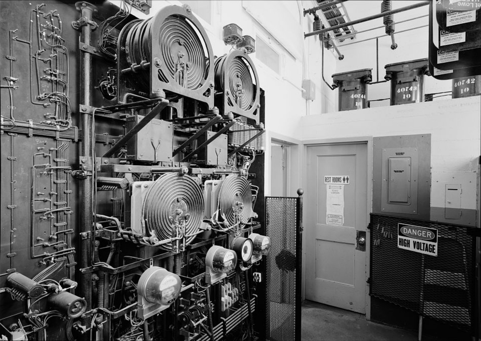
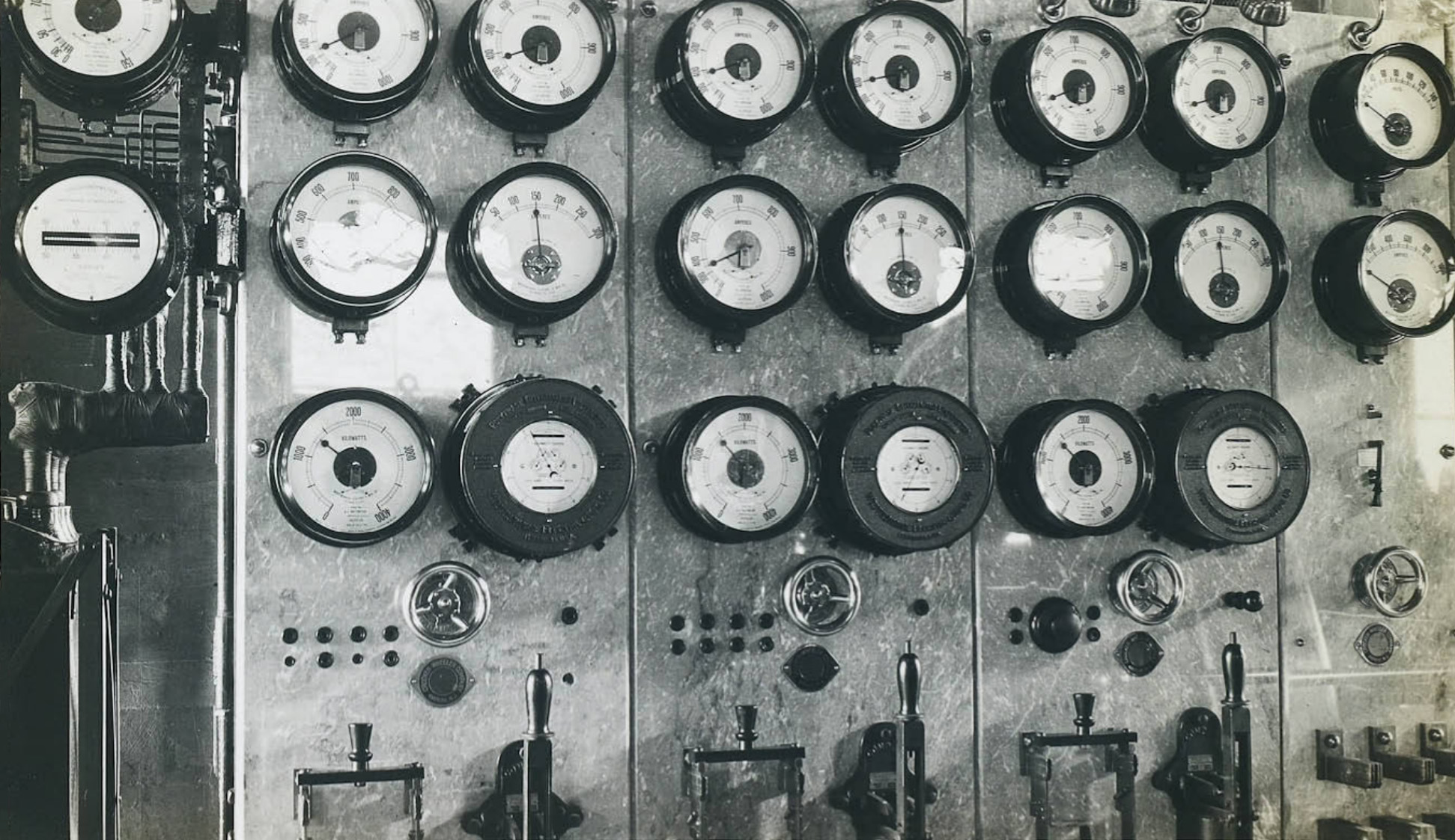 Switchboard at Plant #3 |
 Interior of Bishop Creek Plant #3 |
 G.E. flowmeter attached to #3 machine - Bishop Creek Plant #3 |
 Intake for Plant 4 |
 Intake for Plant 4 |
 Bishop Creek Plant Intake for Plant 4 |
 Plant 3 Powerhouse (Photo and text courtest Library of Congress) |
|
Bishop Creek Plant #3 Intake |
 Aerial view Plant 3 Powerhouse complex (Photo and text courtest Library of Congress) |
 Dwelling Bishop Creek Plant #3 |
 Bachelor's Quarters - Bishop Creek Plant #3 |
Bishop Creek Powerhouse No. 4 |
|
 Bishop Creek Plant #4 From the intake at tail-race at Plant #3, water is supplied to Pant #4 through 7,026' of Redwood stave pipe and two steel pressure pipe lines; one of 5,375' in length and the other 5,675'. The pipes vary in diameter from 4.5' to 2.5' respectively. Plant #4 is the operating headuarters of the Bishop Creek Plants, and here are located a number of miscellaneous structures including operators' cottages, office building, warehouse, garage and clubhouse. |
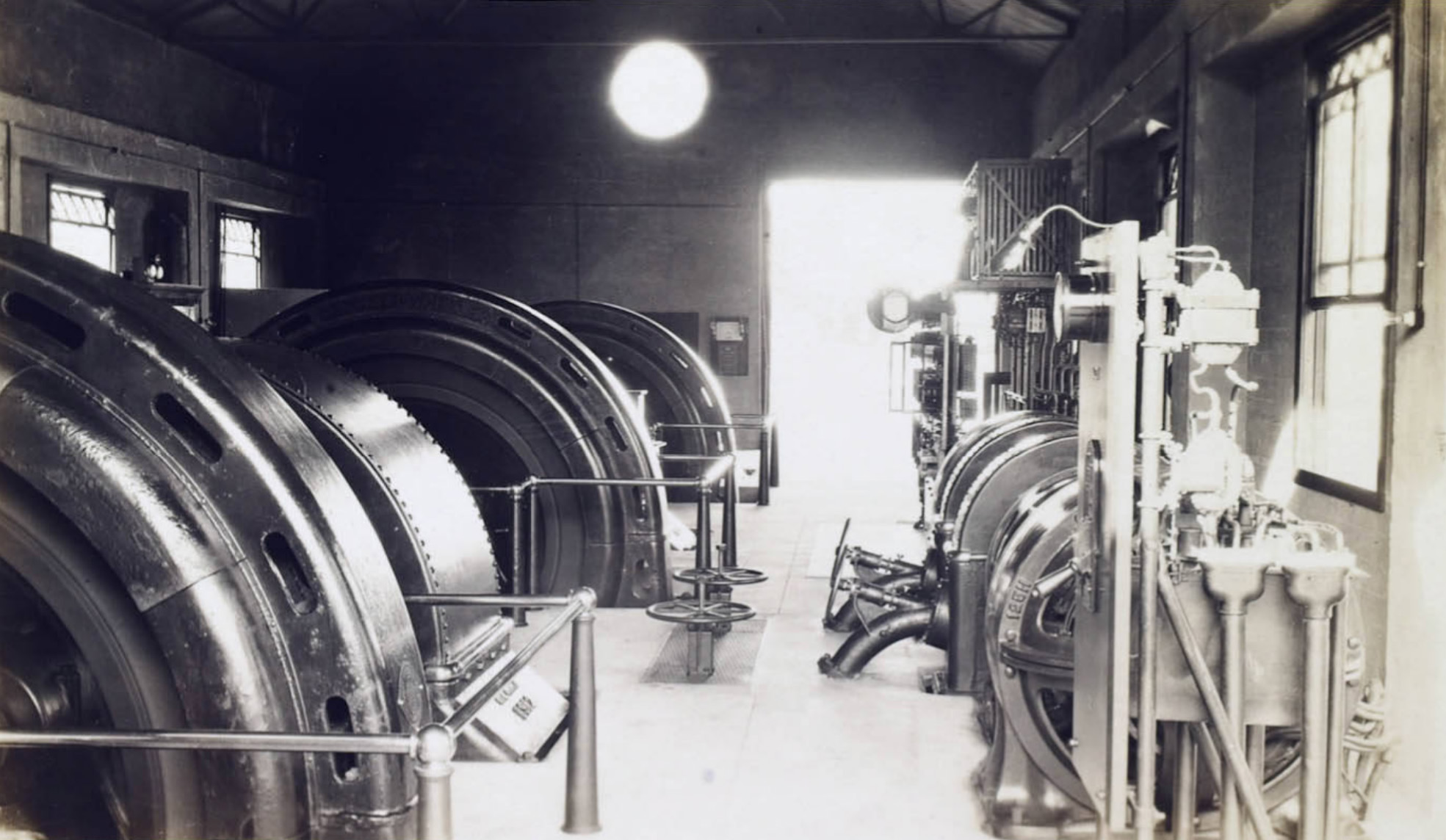
 Bishop Creek Plant #4 interior The generating equipment at Plant #4 consists of five water wheel-driven alternating current generators having a combined capacity of 12,000 horsepower in water wheels and 6,750 Kv-a, in generators. Units 1 and 2 consist of 1,700 horsepower impulse water wheels direct-connected to 750 Kv-1, alternating current generators. Unit 3 consists of a 3,000 horsepower impulse water wheel direct-connected to a 1,750 Kv-a, alternating current generator. Units 4 and 5 consist of a 2,850 horsepower impulse water wheels direct-connected to 1,750 Kv-a, alternating current generators. Each unit is provided with an oil pressure governor equipped for remote control quick shutdown, the water being thrown off the water wheel by means of stream benders, deflectors, or auxiliary nozzles. The auxiliary equipment includes three water wheel-driven direct current exciters, two of which are also privided with induction motors. The switchboard installation consists of a ten panel switchboard complete with generator bus, oil circuit breakers, rheostats and instruments. |
 General view Bishop Creek Plant #4 and #5 Intake Dam |
 Bishop Creek Plant #4 |
 Bishop Creek Plant #4 grounds |
 General view Bishop Creek Plant #4 and #5 Intake Dam |
 Bishop Creek Plant #4 under construction |
 Bishop Creek Plant #4 under construction |
 Powerhouse - Bishop Creek Plant #4 |
 Bishop Creek Plant #4 grounds |
 Steel stave flow line |
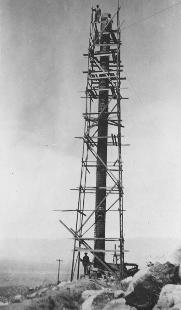 Stand pipe erection |
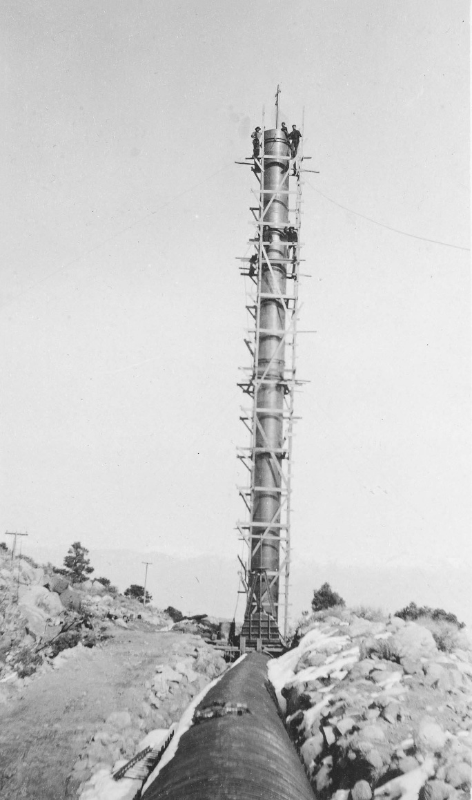 Stand pipe erection |
 Joining wood stave pipe to steel stave pipe at stand pipe erection |
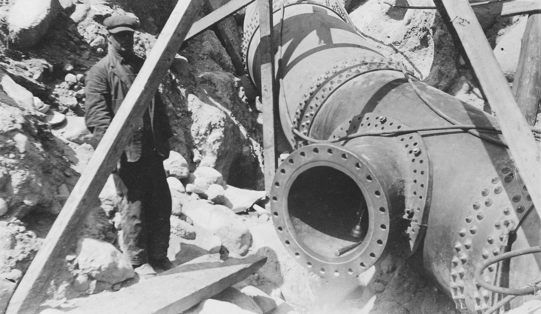 Steel pipe junction |
 Joining wood stave pipe to steel stave pipe at stand pipe erection |
 Bishop Creek Plant #4 in the winter |
 General view in the winter of Bishop Creek Plant #4 and #5 Intake Dam |
 Bishop Creek Plant #4 |
 Bishop Creek Plant #4 |
 Bishop Creek Plant #4 |
 Bishop Creek Plant #4 |
 Bishop Creek Plant #4 canyon area |
 Bishop Creek Plant #4 construction |
|
 Bishop Creek Plant #4 area |
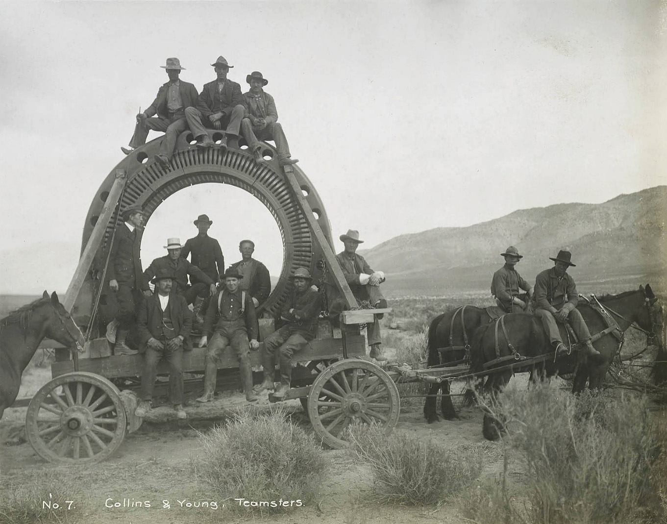 Colins & Young teamsters hauling armature to Bishop Creek Plant #4 |
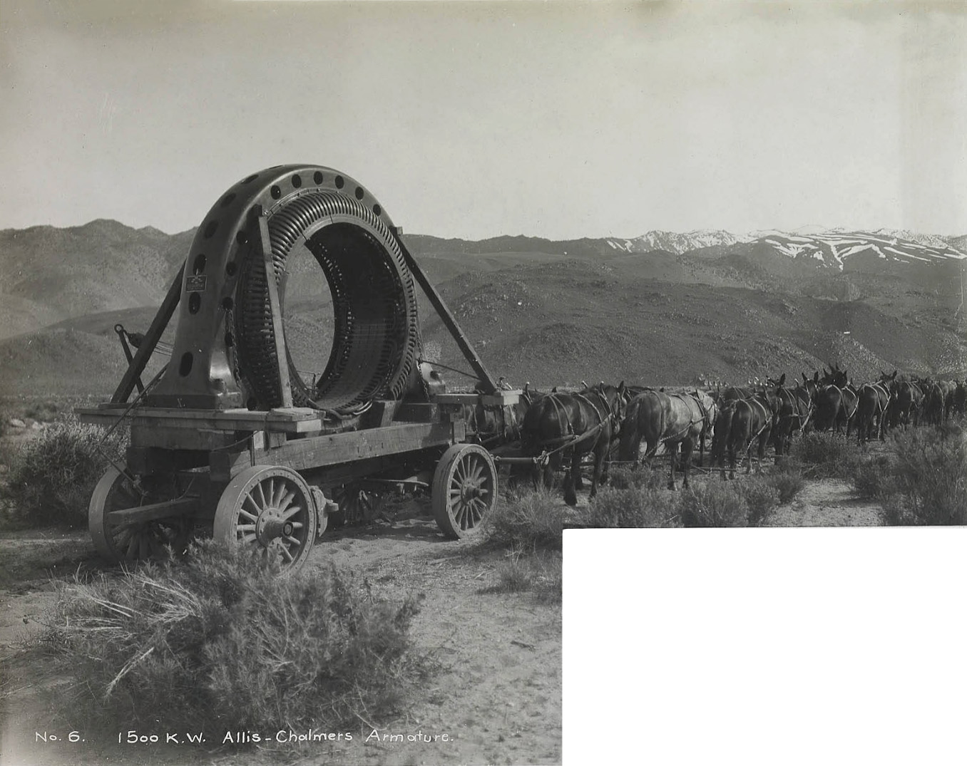 1500 K.W. Allis-Chalmers Armature for Bishop Creek Plant #4 |
 Colins & Young teamsters hauling armature from Laws SPNG RR depot to Bishop Creek Plant #4 |
|
 Colins & Young teamsters hauling armature from Laws SPNG RR depot to Bishop Creek Plant #4 - 1905 |
|
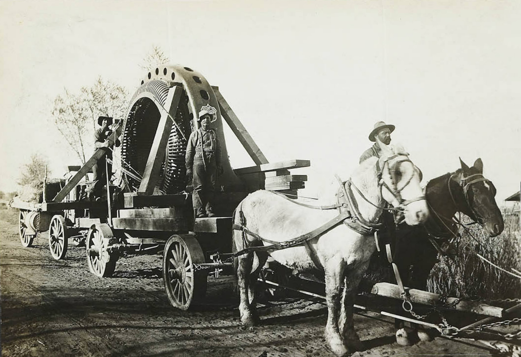 Colins & Young teamsters hauling armature to Bishop Creek Plant #4 |
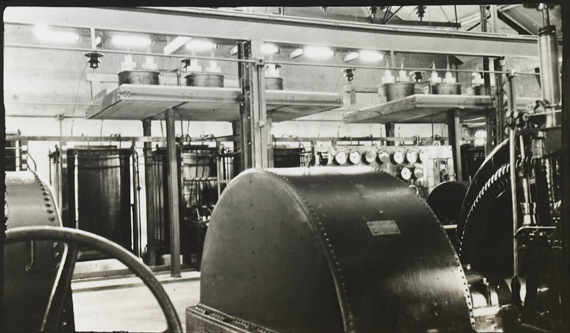
 Bishop Creek Plant 4 interior |
 Bishop Creek Plant 4 interior |
 Switchboard Bishop Creek Plant #4 |
 Bishop Creek Plant #4 interior |
 Bishop Creek Plant #4 interior |
 Bishop Creek Plant #4 interior |
 Bishop Creek Plant 4 interior |
 Bishop Creek Plant #4 interior |
|
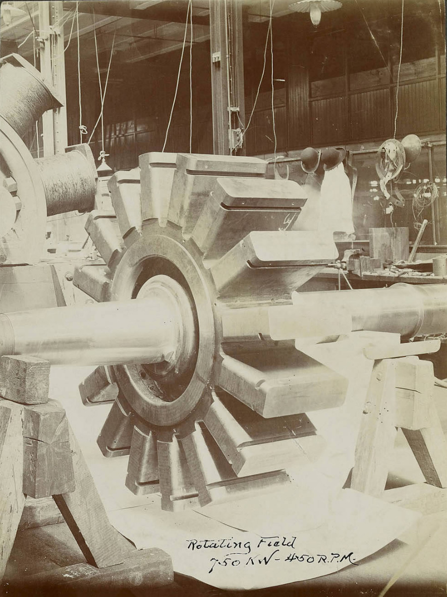 Rotating field 750 K.W., 450 RPM R. D. Type |
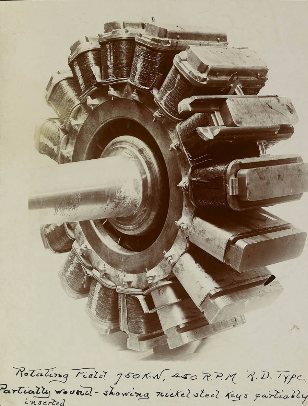 Rotating field 750 K.W., 450 RPM R. D. Type - Partially Wound showing nickel steel keys |
 Bishop Creek Plant #4 interior |
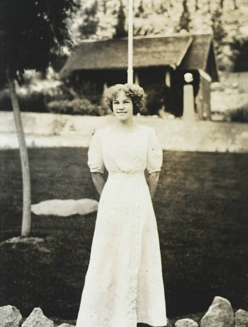 Bishop Creek Plant #4 - Miss May Grandquist "Queen" Inyo County Festival and Plant 4 resident |
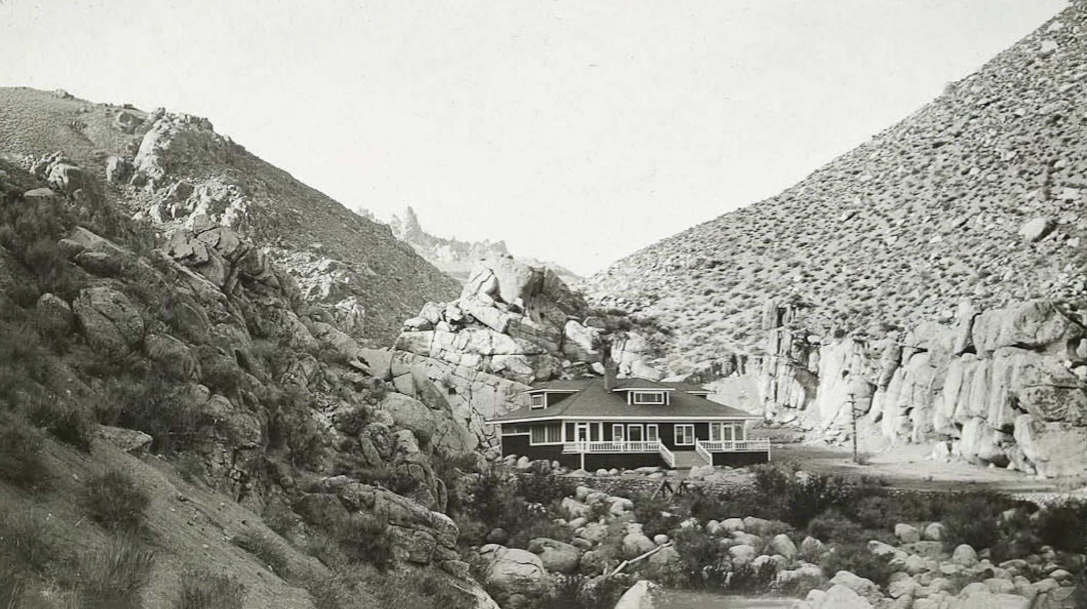 Bishop Creek Plant #4 Clubhouse |
 Bishop Creek Plant #4 Clubhouse |
 Bishop Creek Plant #4 Operator's Quarters Married employees are provided with comfortable cottages as at the other plants. A combined boarding house and clubhouse is maintained for single employees, visiting officials and guests. |
 Switch house and lightning arrester at Plant #4 |
 Plant 4 residential complex (Photo and text courtest Library of Congress) |
 Plant 4 residential complex (Photo and text courtest Library of Congress) |
 Winter view from Bishop Creek Plant #4 towards Owens Valley from the clubhouse. |
 View from Bishop Creek Plant #4 towards Owens Valley |
 Operator's cottage at Bishop Creek Plant #4 |
 Cottage at Bishop Creek Plant #4 |
 Frame School at Bishop Creek Plant #4 |
 Machine and Blacksmith shop at Bishop Creek Plant #4 |
 Oil Shed at Bishop Creek Plant #4 |
 Office and Warehouse at Bishop Creek Plant #4 |
 Replacing a standing pipe at Plant 4 |
 Replacing a standing pipe at Plant 4 |
 Replacing a standing pipe at Plant 4 |
 Replacing a standing pipe at Plant 4 |
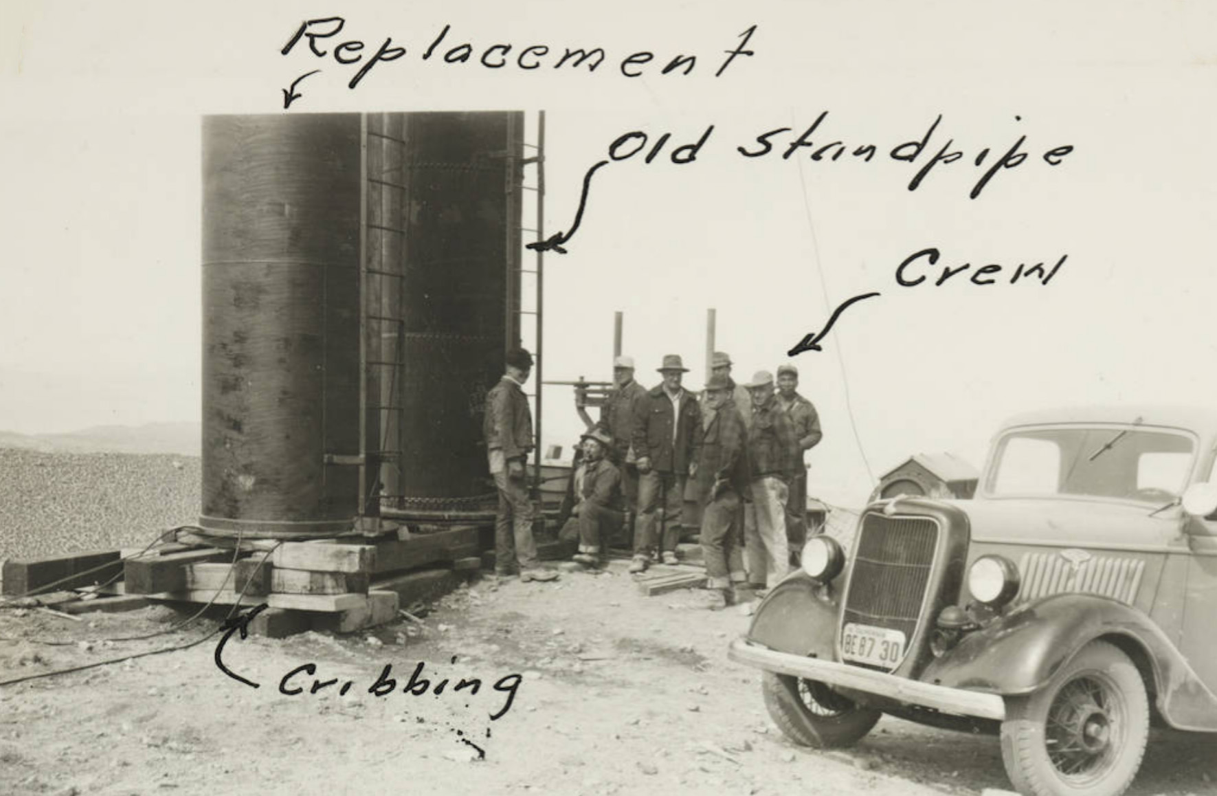 Replacing a standing pipe at Plant 4 |
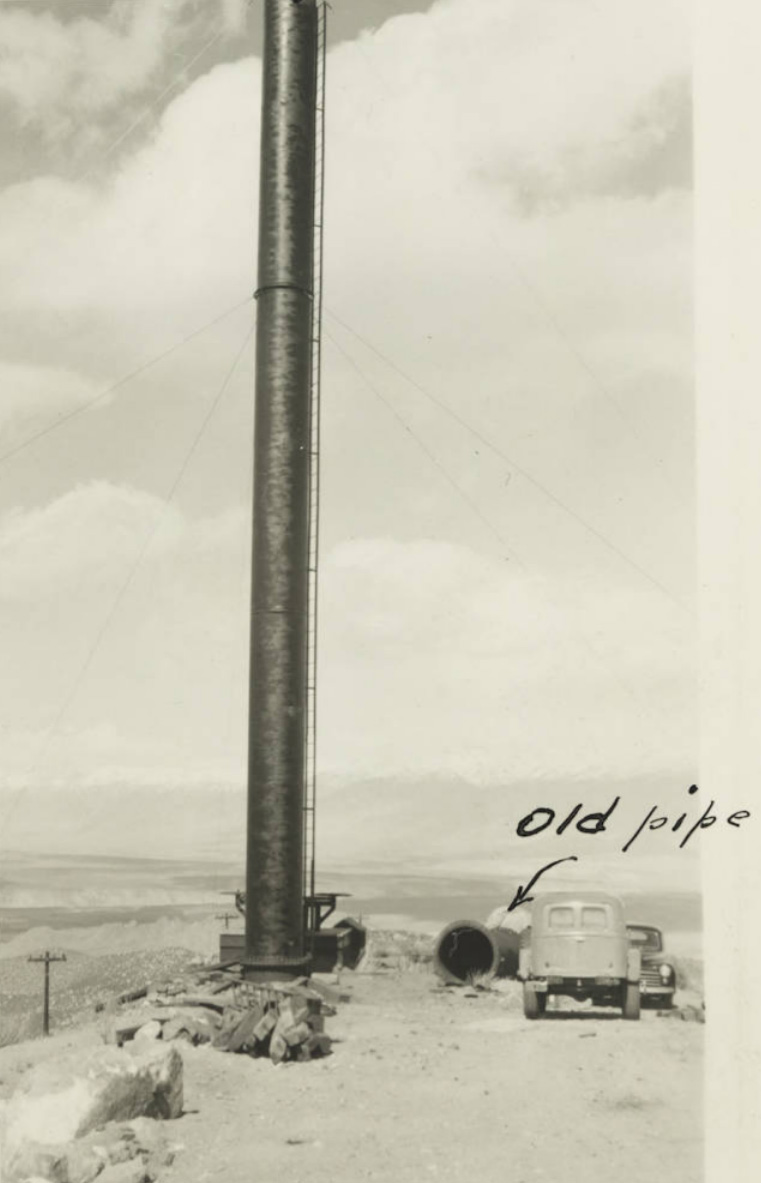 Replacing a standing pipe at Plant 4 |
 Dredging supervisors L/R: Mike Zuvella and Billy Young |
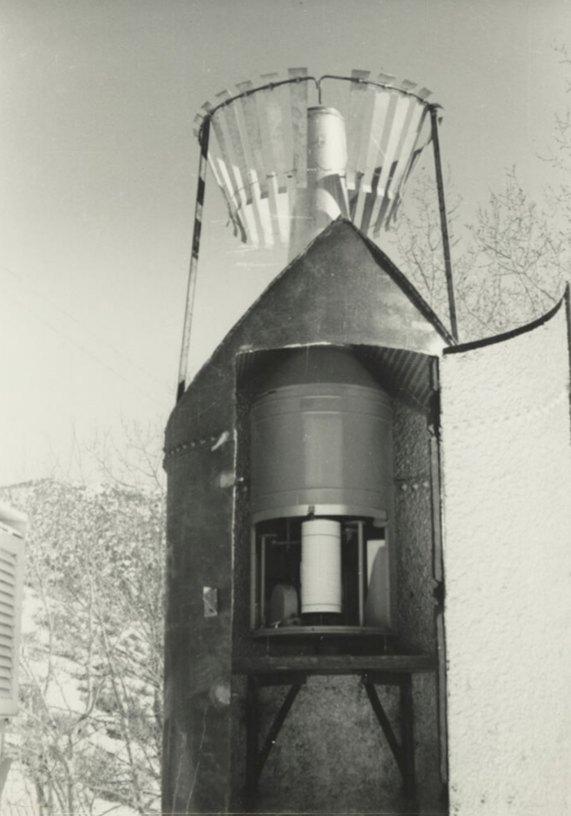 A "Snow Catcher" |
Dredging Intake #4 |
 Dredging Intake #4 |

Bishop Creek Powerhouse No. 5 |
|
 Bishop Creek Plant #5 Water from the forebay at Plant #4 is delivered to Plant #5 through 3,470' of wood stave pipeline and 2 steel pressure pipe lines, one 4,840' in length and the other 4,878' in length. The pipes vary in diameter from 5' to 3.5' at the power house. The generating equipment consists of one horizontal impulse water wheel and one single discharge horizontal turbine with a combined capacity of 5,700 horsepower direct-connected to two alternating current generators with combined capacity of 3,545 Kv-a. |
 Hauling a piece of equipment to Bishop Creek Plant #5 |
 General view Bishop Creek Plant #5 |
 Interior Bishop Creek Plant #5 showing Exciter and Water Wheels for 1500 K.W. Generator |
 Plant 5 Powerhouse looking up the northeast tailrace (Photo and text courtest Library of Congress) |
 East end of Plant 5 and east tailrace (Photo and text courtest Library of Congress) |
 Intake Dam for Plant 6 |
 Plant 5 Powerhouse |
 Bishop Creek Plant #5 |
 Interior Plant #5 |
Bishop Creek Powerhouse No. 6 |
|
 Bishop Creek Plant #6 Water from the forebay at Plant #5 is supplied to Plant #6 through 3,000' of wood stave pipe and 4,360 feet of steel pressure pipeline. The wood stave pipe is 5' in diameter and the steel pipe is 4.5' in diameter. The generating equipment consists of a double runner impulse water wheel with a capacity of 2,850 horsepower direct-connected to an alternating current generator with a capacity of 2,220 Kv-a. The substation located at Plant #6 includes high voltage switching equipment in addition to the bank of 750 Kv-a transformers. The distribution substation supplying the towns of Bishop and Big Pine is also located at Bishop Creek Plant #6. |
 East side Plant 6 Powerhouse and Tailrace (Photo and text courtest Library of Congress) |
 Bishop Creek Plant #6 |
 60" wood stave pipe for Bishop Creek Plant #6 |
 General view of the Bishop Creek Plant #6 powerhouse and outdoor transformers. |
 General view of the Bishop Creek Plant #6 powerhouse and outdoor transformers. |
 General view of the Bishop Creek Plant #6 powerhouse and outdoor transformers. |
 Bishop Creek Plant #6 interior |
 Interior Bishop Creek Plant #6 showing governing devices and partial view of water wheels and generator. |
 Interior Bishop Creek Plant #6 2000 K-va generator, showing safety guard about the rotor |
 Intake Bishop Creek Plant #6 |
 Intake Bishop Creek Plant #6 Intake Bishop Creek Plant #6 |
 Fobes 40 Ranch - Transformer at location ready for hanging - March 1952 |
 Pulling a transformer on a toboggan to Fobes 40 Long Valley Ranch - March 1952 L/R: Cliff Jones, Howard Lambert, Rodney Montrose, Ed Johnson, Ray Humphrey |
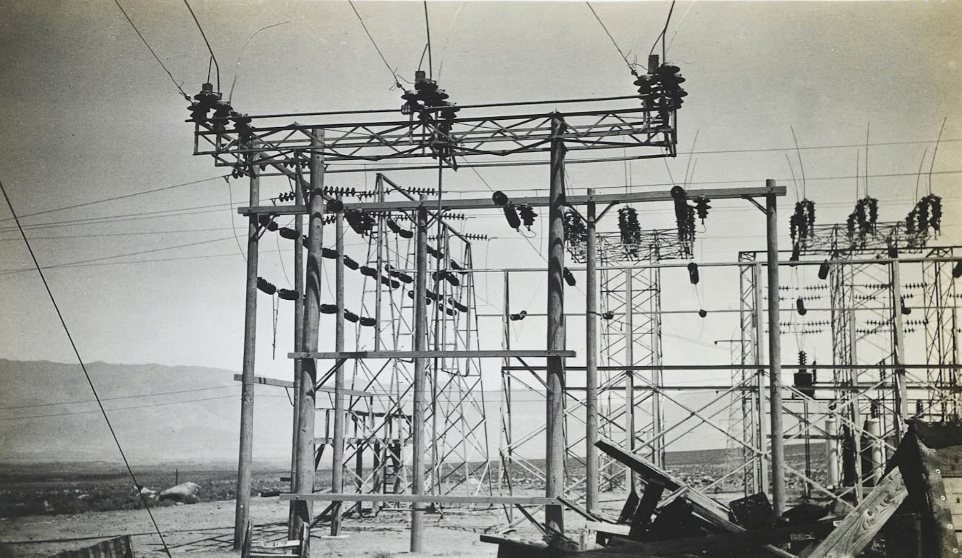
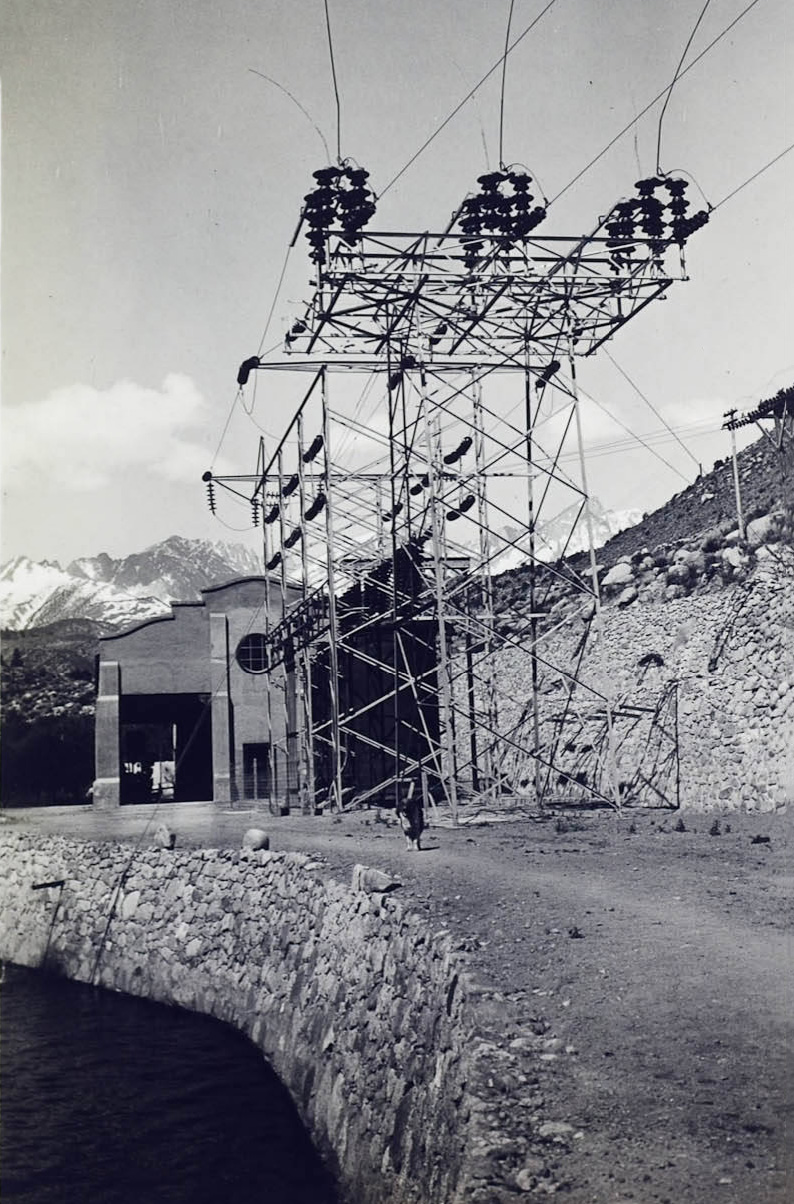
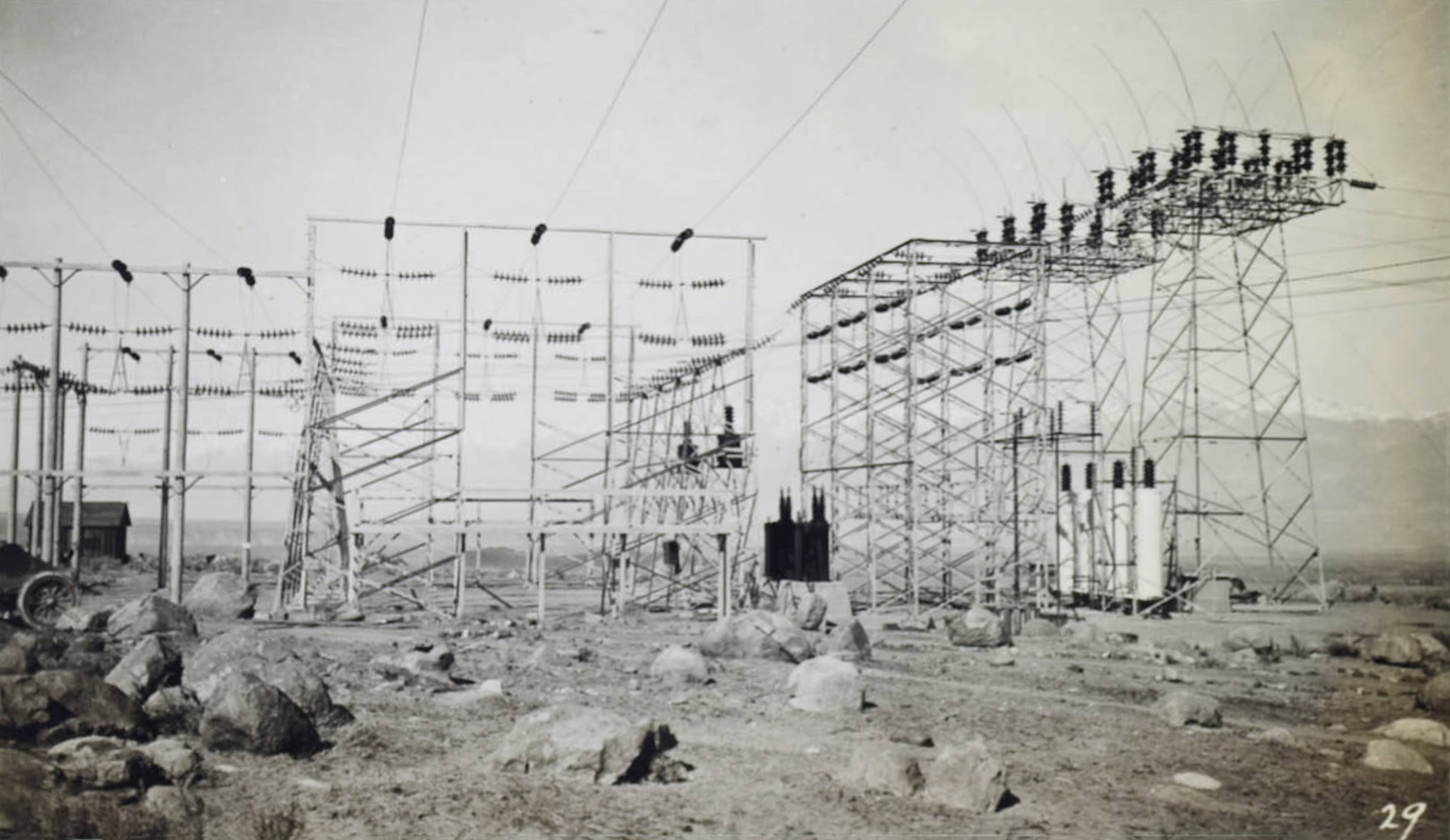
 Situated on Bishop Creek near Plant #6, here practically all of the power generated at the hydro-electric plants on Bishop Creek, Rush Creek, Leevining Creek and in Owens River Gorge, is pooled for distribution to Nevada, Southern California, and for resale in Arizona and Lower California. From this station two outgoing 55,000 volt transmissioin lines supply the Nevada District; and the 238 mile double circuit, three phase, 130,000 volt steel tower transmission line extended to the main sutsbation of the Southern Sierras Power Company at San Bernardino. The Control Station is the headquarters of the Superintendentof Transmission. |
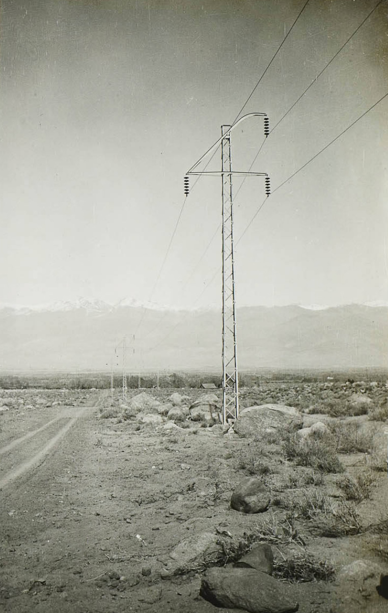
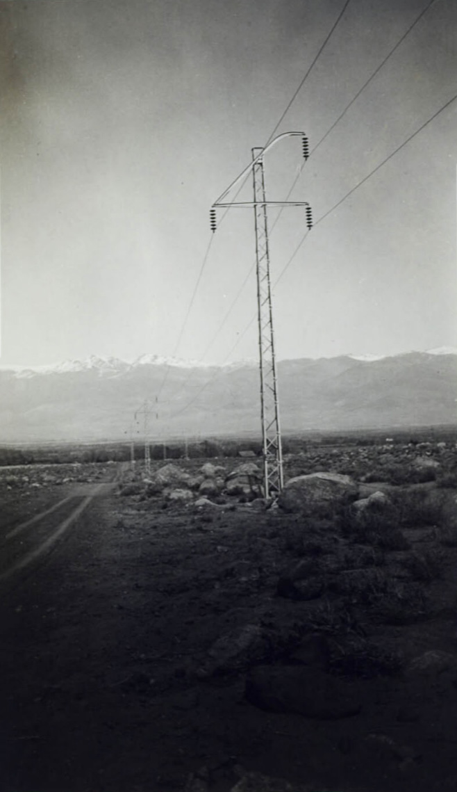
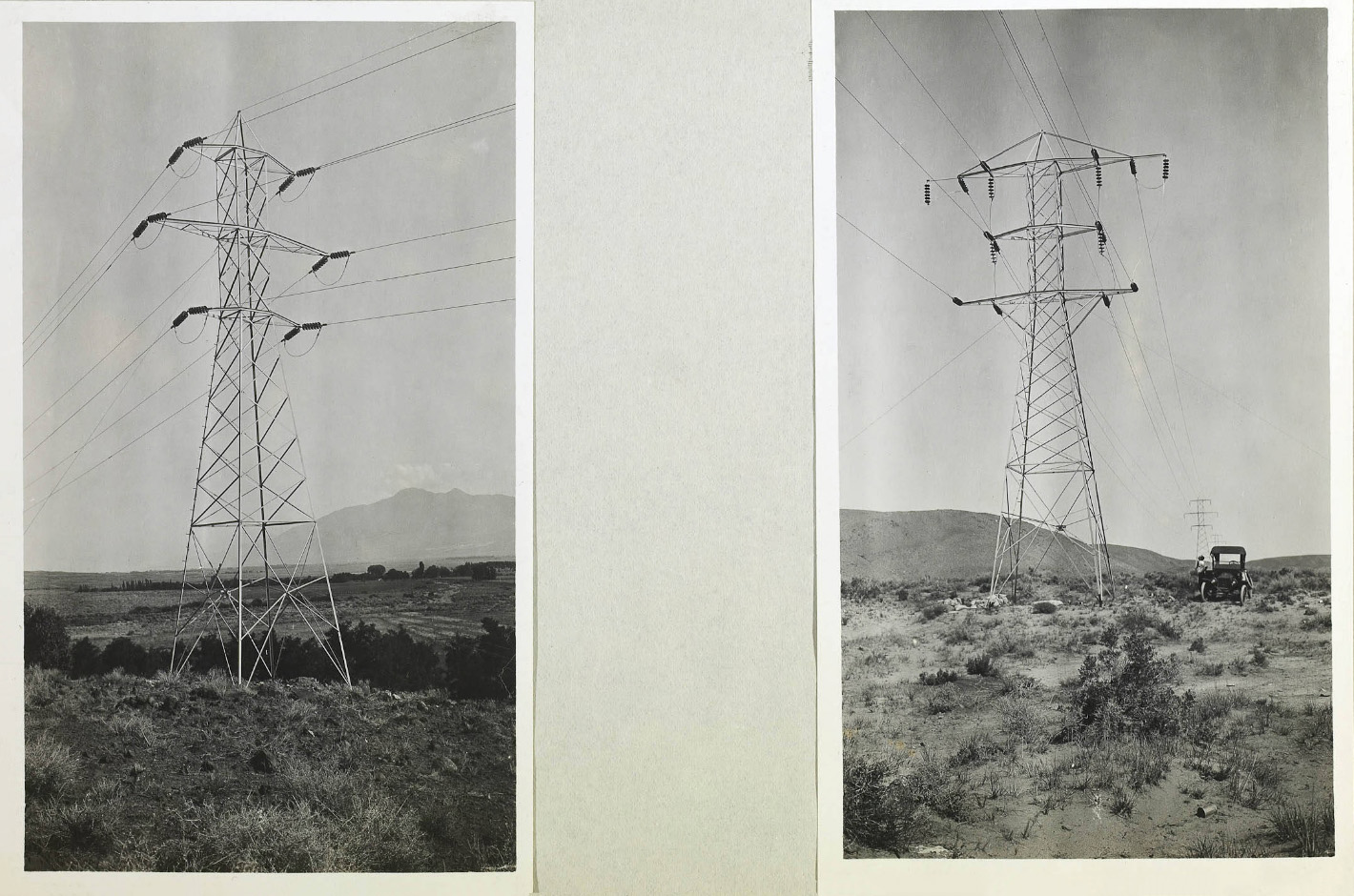
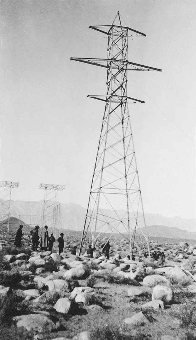
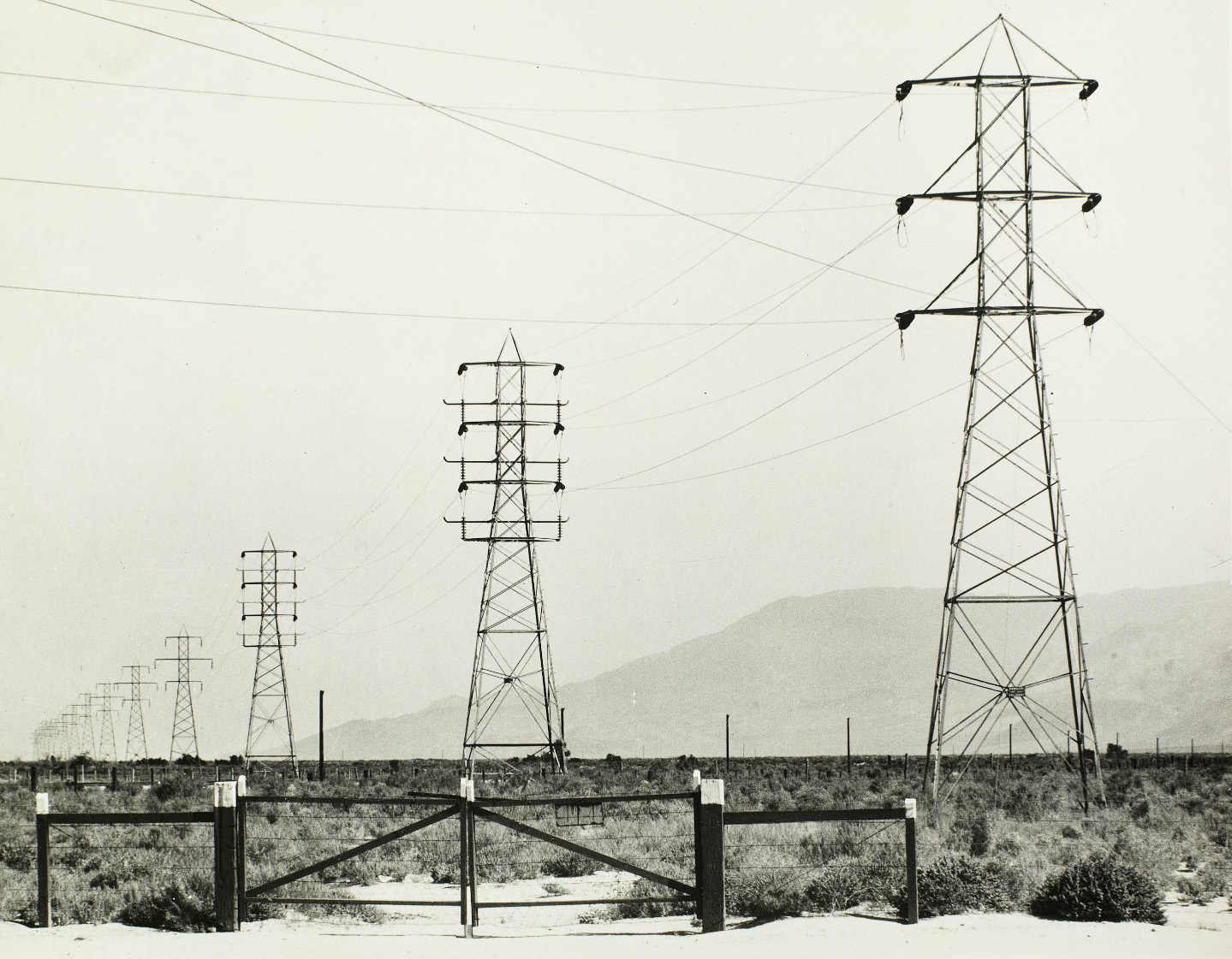 This transmission line, connecting Control Station, Bishop Creek, with the San Bernardino Substation, is a 140,000 volt two-circuit steel tower line 238 miles in length. The towers are 70' in height and are spaced eight to the mile, and vary in weight from 3,700 pounds for standard suspension towers to 11,400 pounds for Santa Fe Railroad crossing towers. |
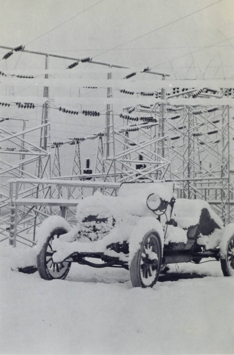 Snow storm at the Control Station near Bishop Creek Plant #6 |
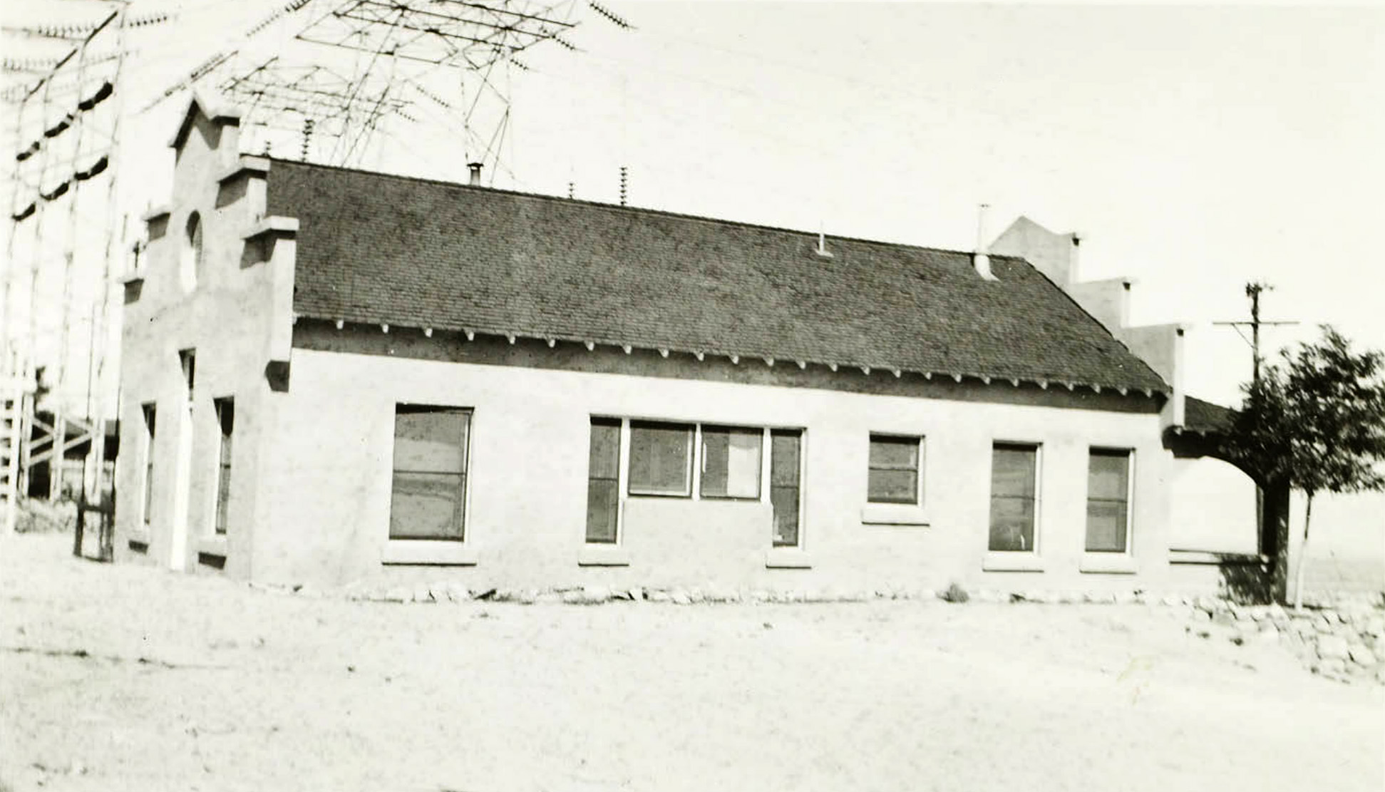
 Control Station office near Bishop Creek Plant #6 |
 Wishbone transmission tower between Bishop Creek Plant #6 and the Control Station |
 Near view of outdoor transformers at Bishop Creek Plant #6 |
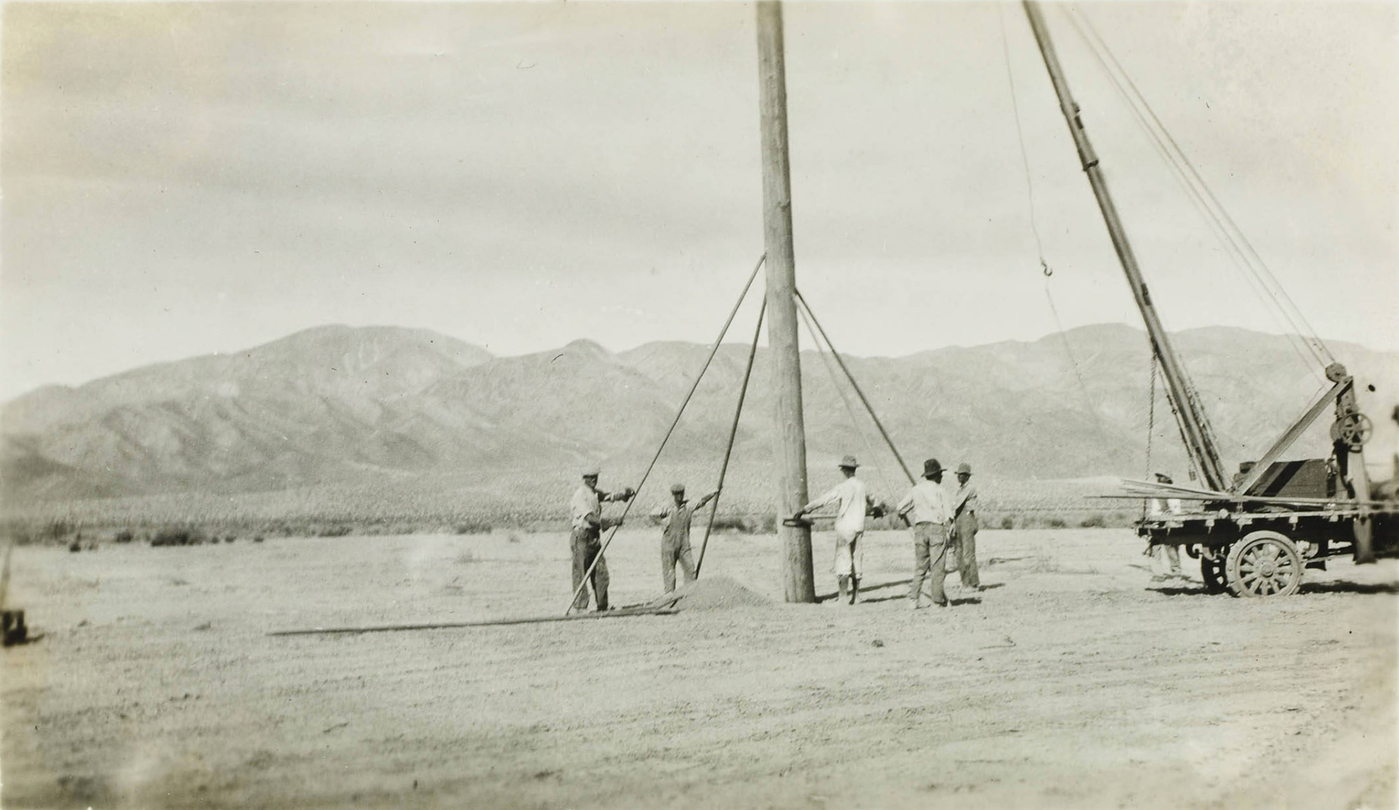
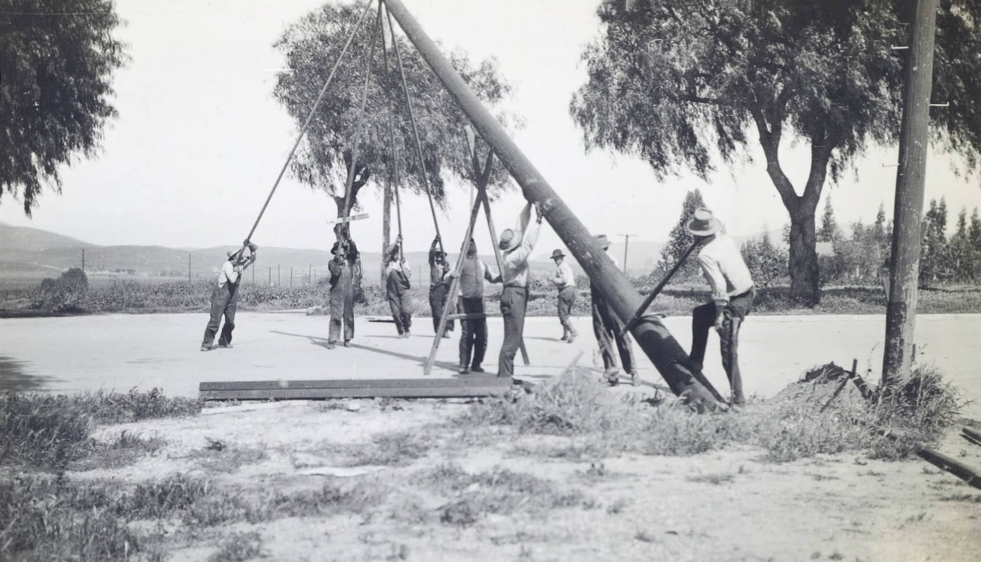 Manually erecting a transmission tower pole. |
 Control Station near Bishop Creek Plant #6 |
 Control Station |
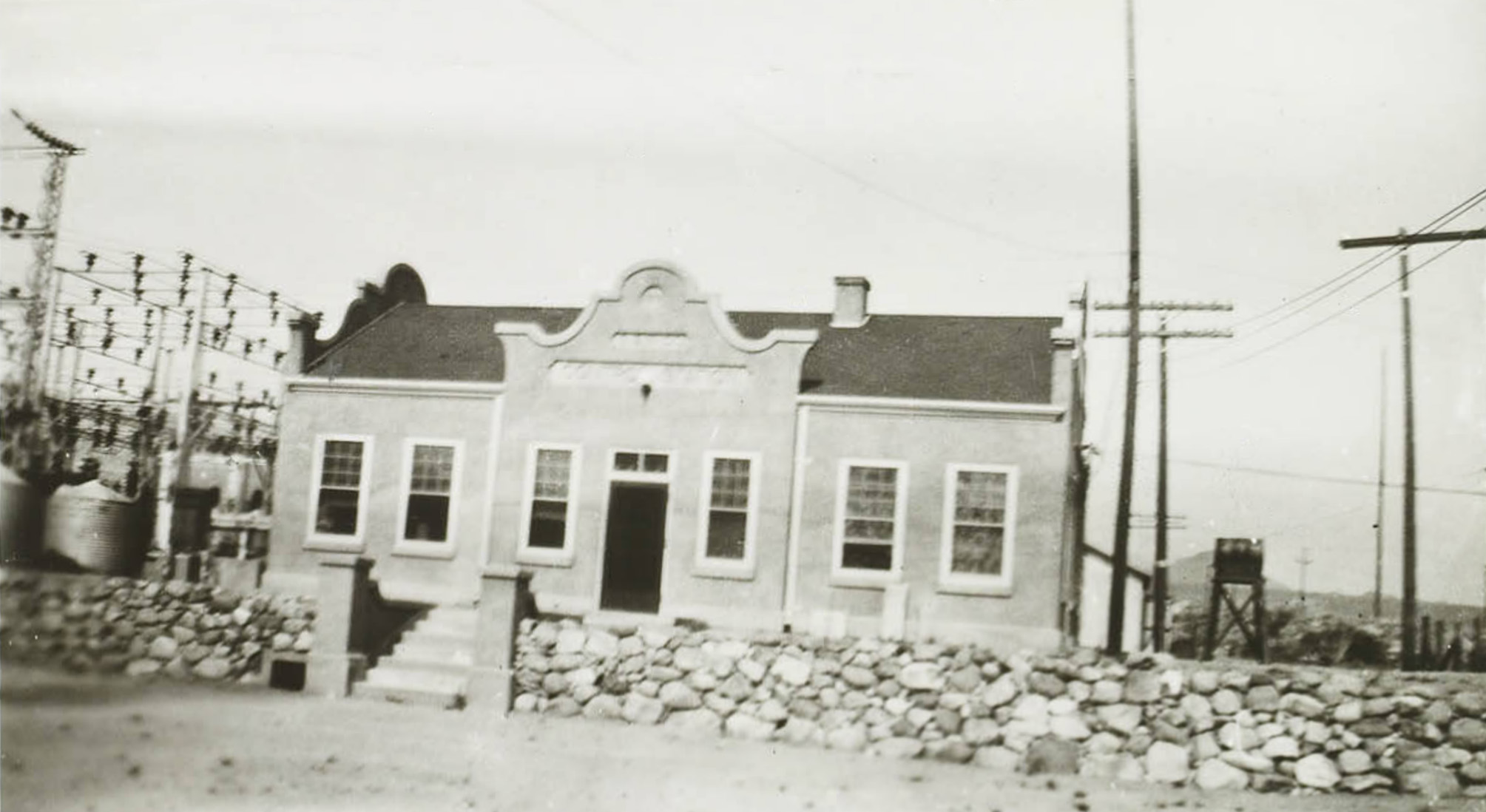 Office and Switch Station |
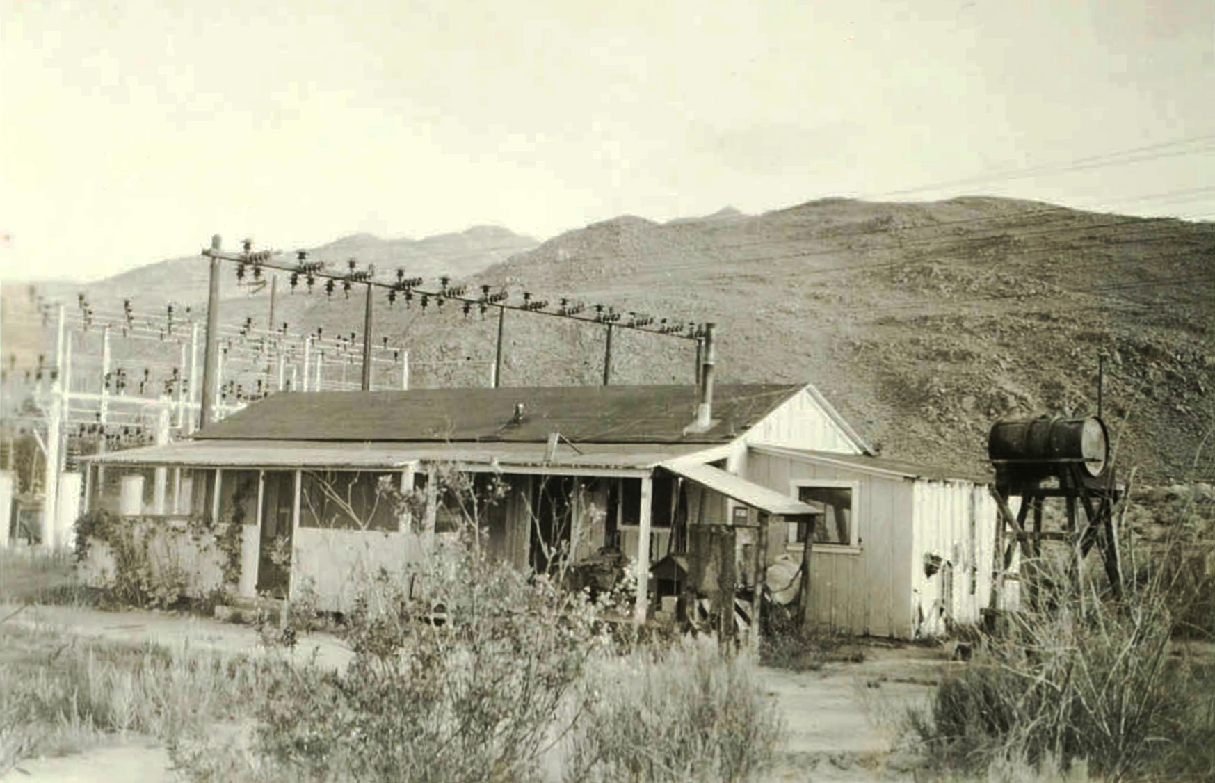 Control Station dwelling |
 Control Station garage and water tank |
Big Pine Creek Powerhouse Big Pine Creek |
|
 Big Pine Powerhouse (Photo and text courtest Library of Congress) |
 Big Pine Powerhouse and transformer (Photo and text courtest Library of Congress) |
 Angle and Transposition transmission towers near Independence, CA - October 1913 |
|
Cottonwood Powerhouse Cottonwood Creek |
|
 Installing side guys on tower near Lone Pine - 1952 |
 Installing side guys on tower near Lone Pine - 1952 |
 Cottonwood Power Plant looking east (Photo and text courtest Library of Congress) |
 Overhaul of Pelton Wheel, Westinghouse Generator, 750KW, 2300 volts, 137 Amps, 600 RPM (Photo and text courtest Library of Congress) |
 Cottonwood Generator Floor Looking West (Photo and text courtest Library of Congress) |
 Cottonwood Power Plant looking east (Photo and text courtest Library of Congress) |
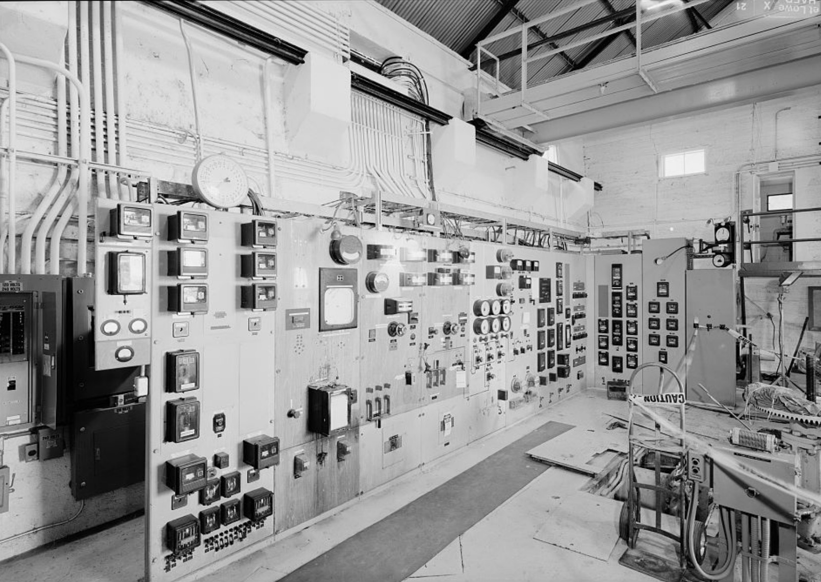 Cottonwood Power Plant Control Panel (Photo and text courtest Library of Congress) |
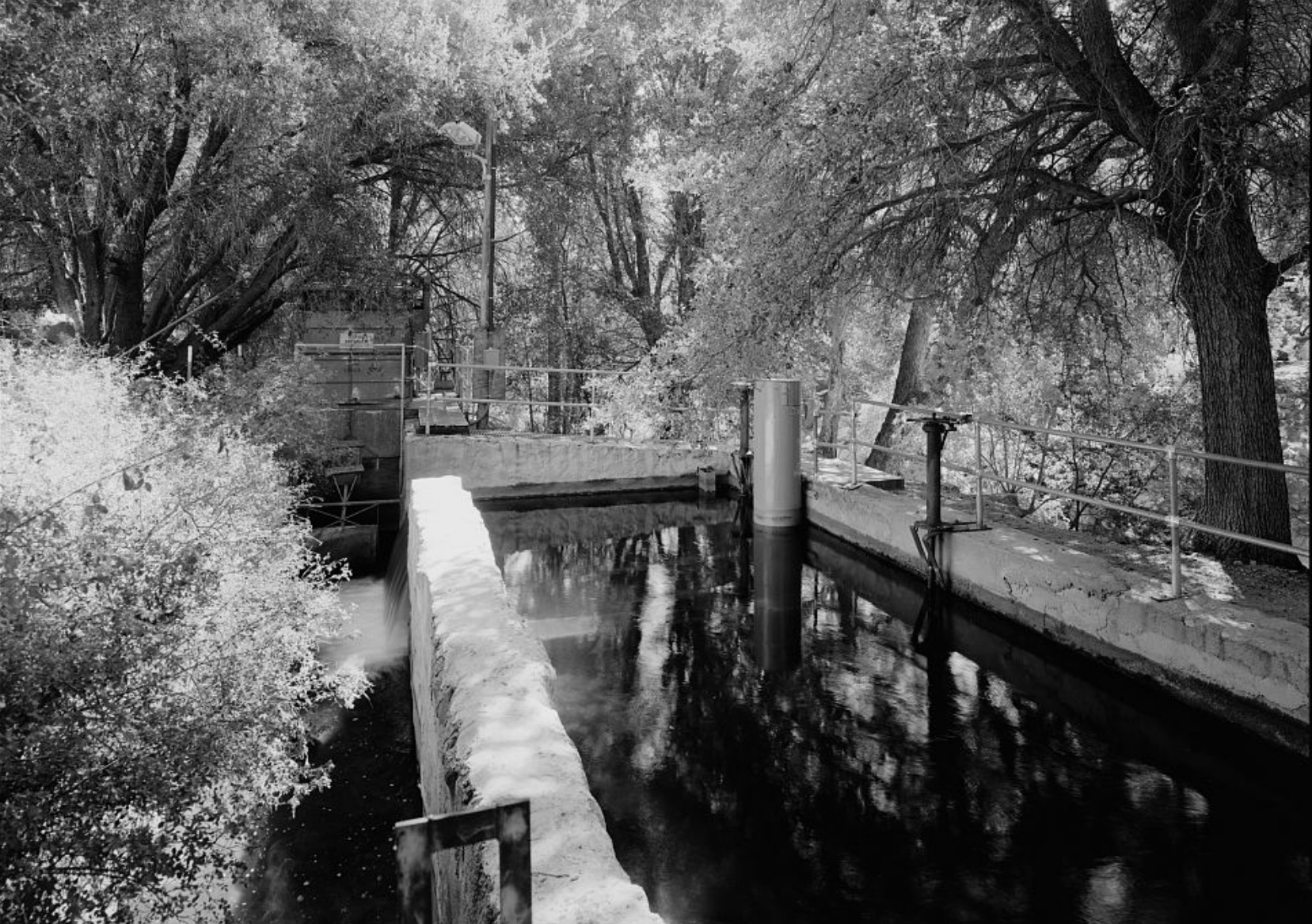
 Cottonwood Creek Overhead Looking South (Photo and text courtest Library of Congress) |
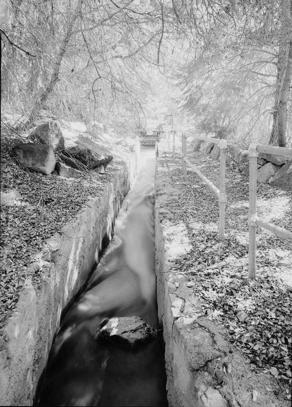
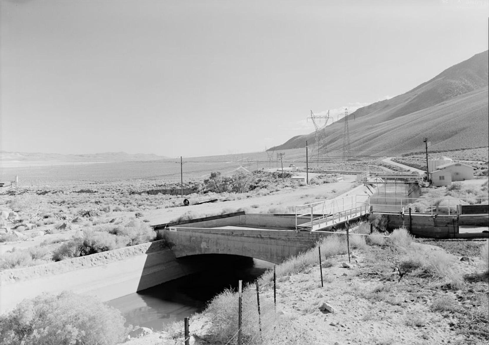
 Settling Pond, Intake and Raceway for Cottonwood Power Plant (Photo and text courtest Library of Congress) |
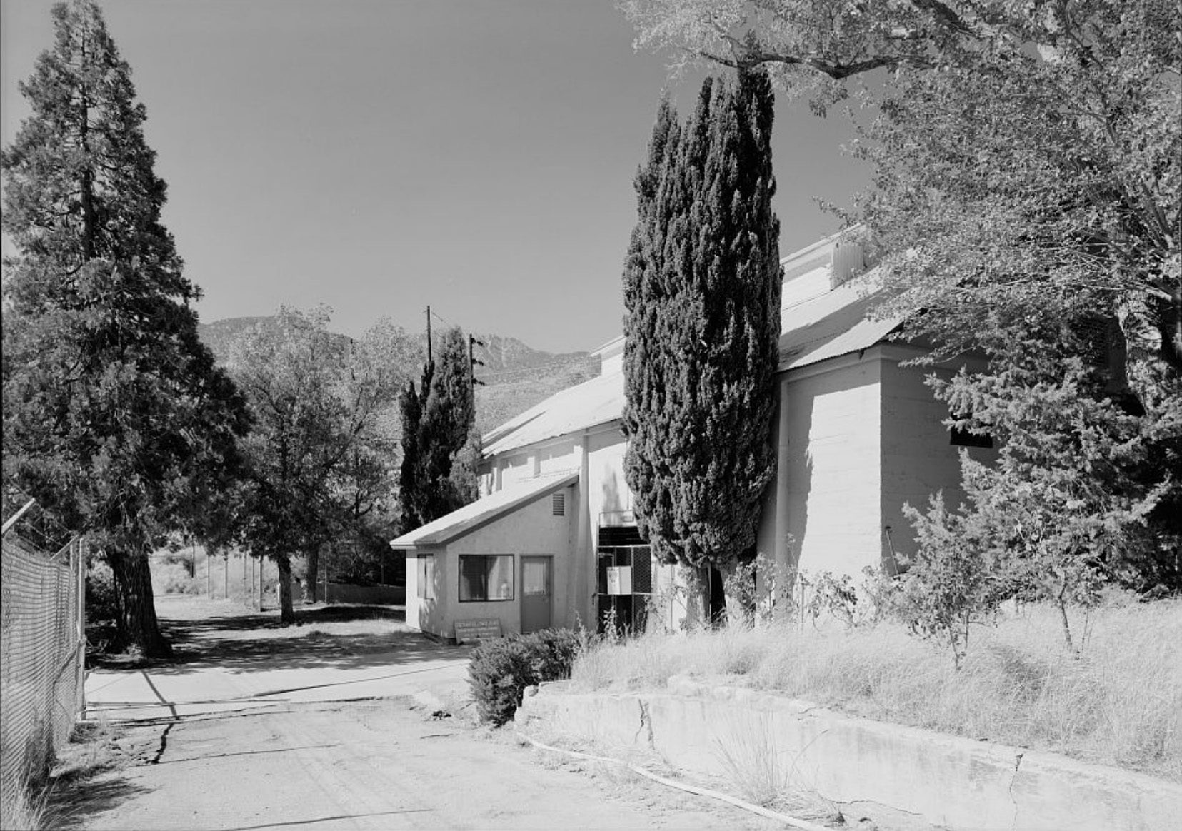 Cottonwood Power Plant South Wall - Looking West (Photo and text courtest Library of Congress) |
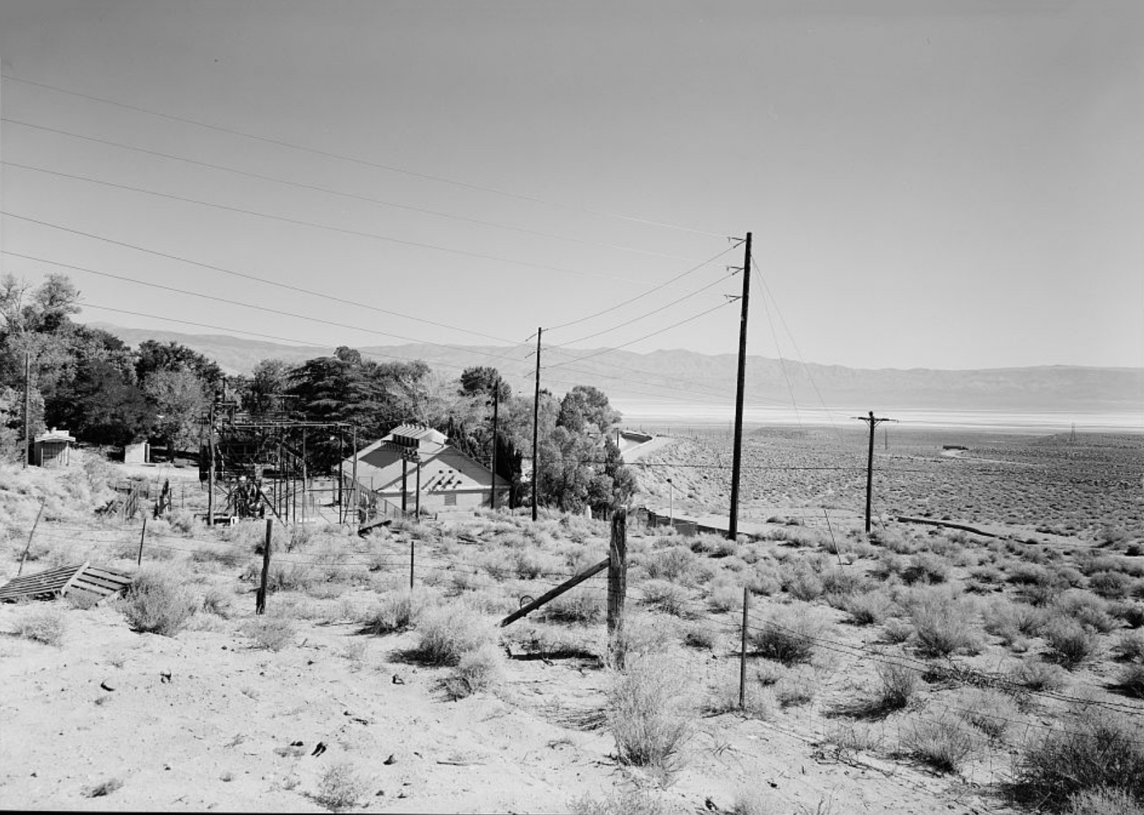
Haiwee Powerhouse Los Angeles Aqueduct - Haiwee Reservoir |
|
 Haiwee Power Plant Transmission Lines (Photo courtesy Digital Public Library) |
 Haiwee Power Plant Step up transformers in Foreground, Surge Tank at To of Ridge (Photo and text courtest Library of Congress) |
 Haiwee Power House Bypass Channel in the Foreground, Looking Northwest (Photo and text courtest Library of Congress) |
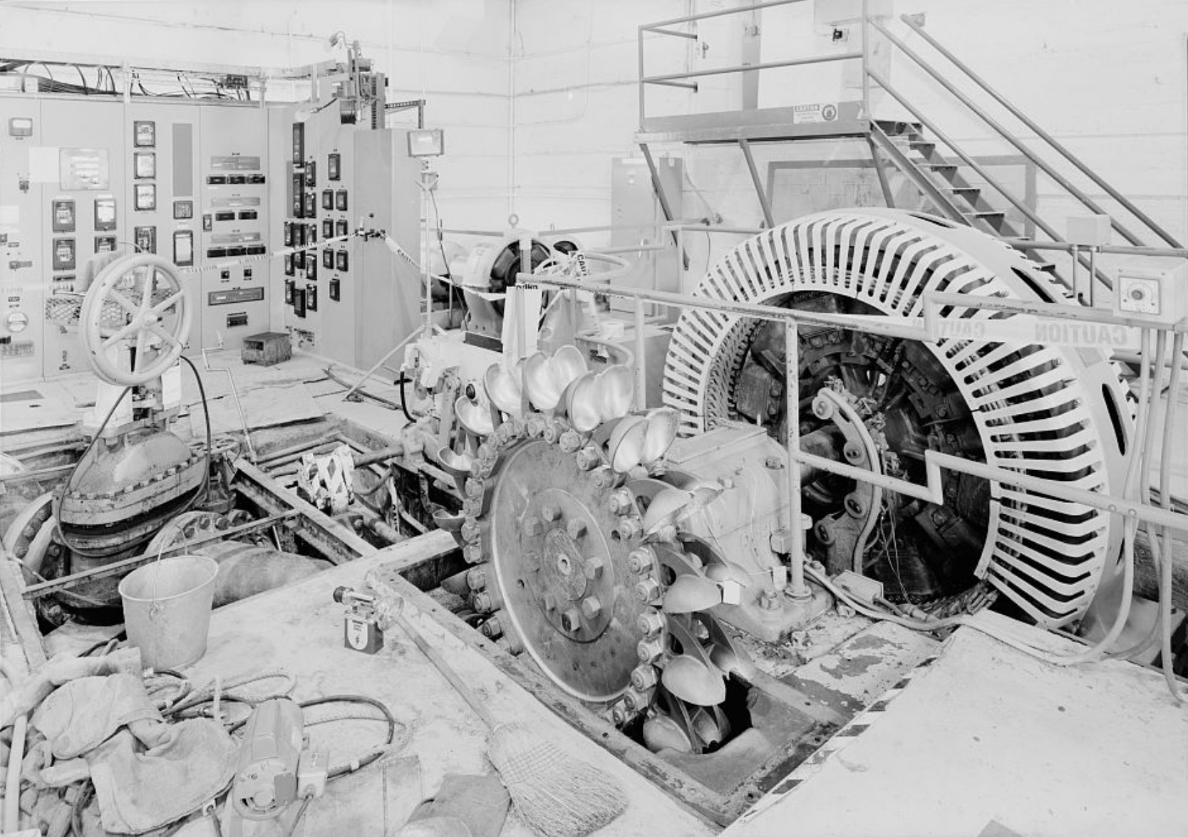
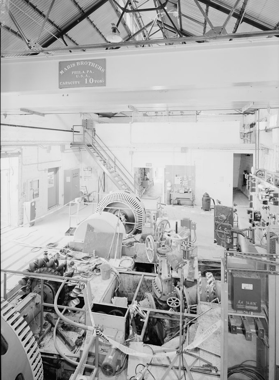
 Generator Floor Looking Northwest, GE AC Generator 306/368 AMP 375 RPM, 60/50 Cycles, 2300KW (Photo and text courtest Library of Congress) |
 Disconnect alley, Referring to the switches on the left. (Photo and text courtest Library of Congress) |
 Governor and speed control mechanisms tank At left an accumulator ttank which stores air pressure (Photo and text courtest Library of Congress) |
 Slate mounted control board (Photo and text courtest Library of Congress) |
 Control room on the control floor (Photo and text courtest Library of Congress) |
 Haiwee Power Plant floor looking east (Photo and text courtest Library of Congress) |
 Backside of the circuit control board to the disconnect alley Exciter unit, rheostats form big circular units (Photo and text courtest Library of Congress) |
Transmission Lines |
|
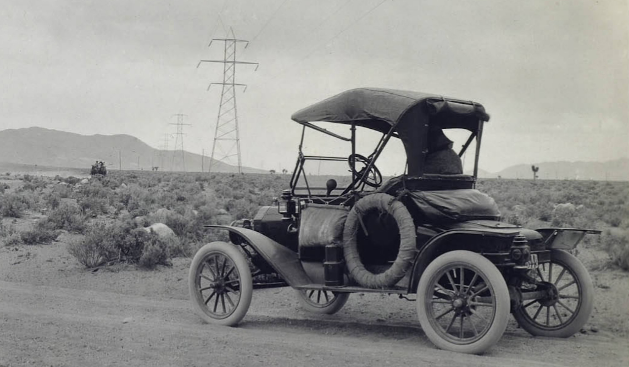
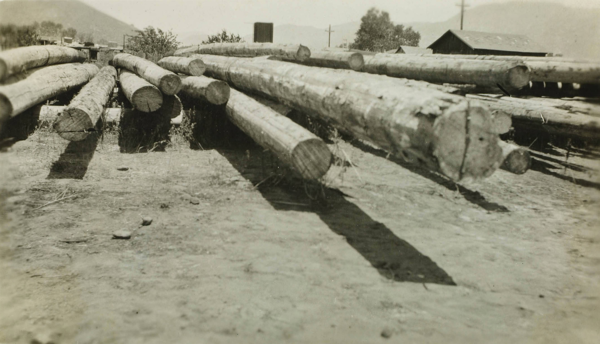 Wood transmission poles in the Mojave Desert "Pole Yard" |
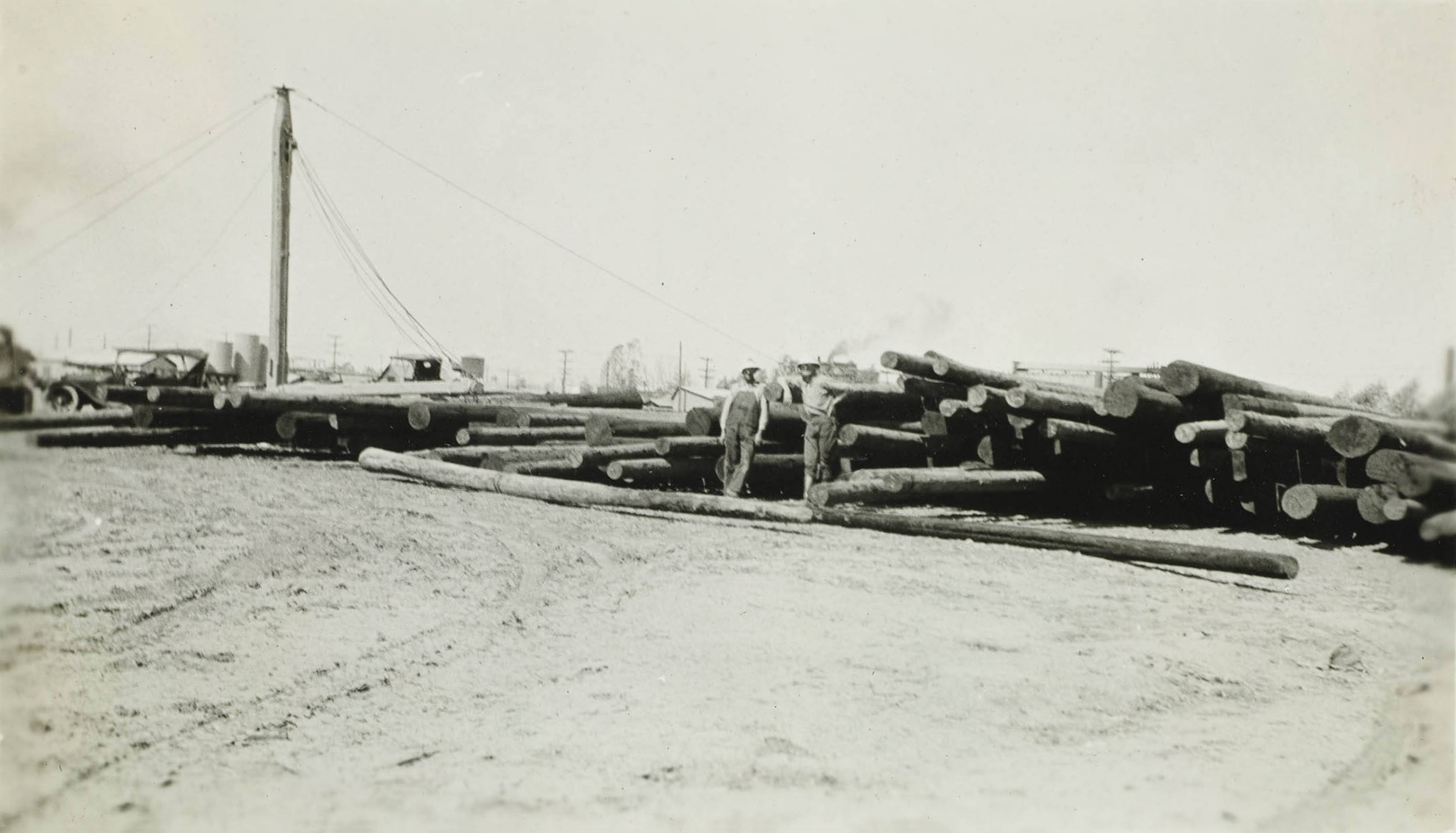 Wood transmission poles in the Mojave Desert "Pole Yard" |
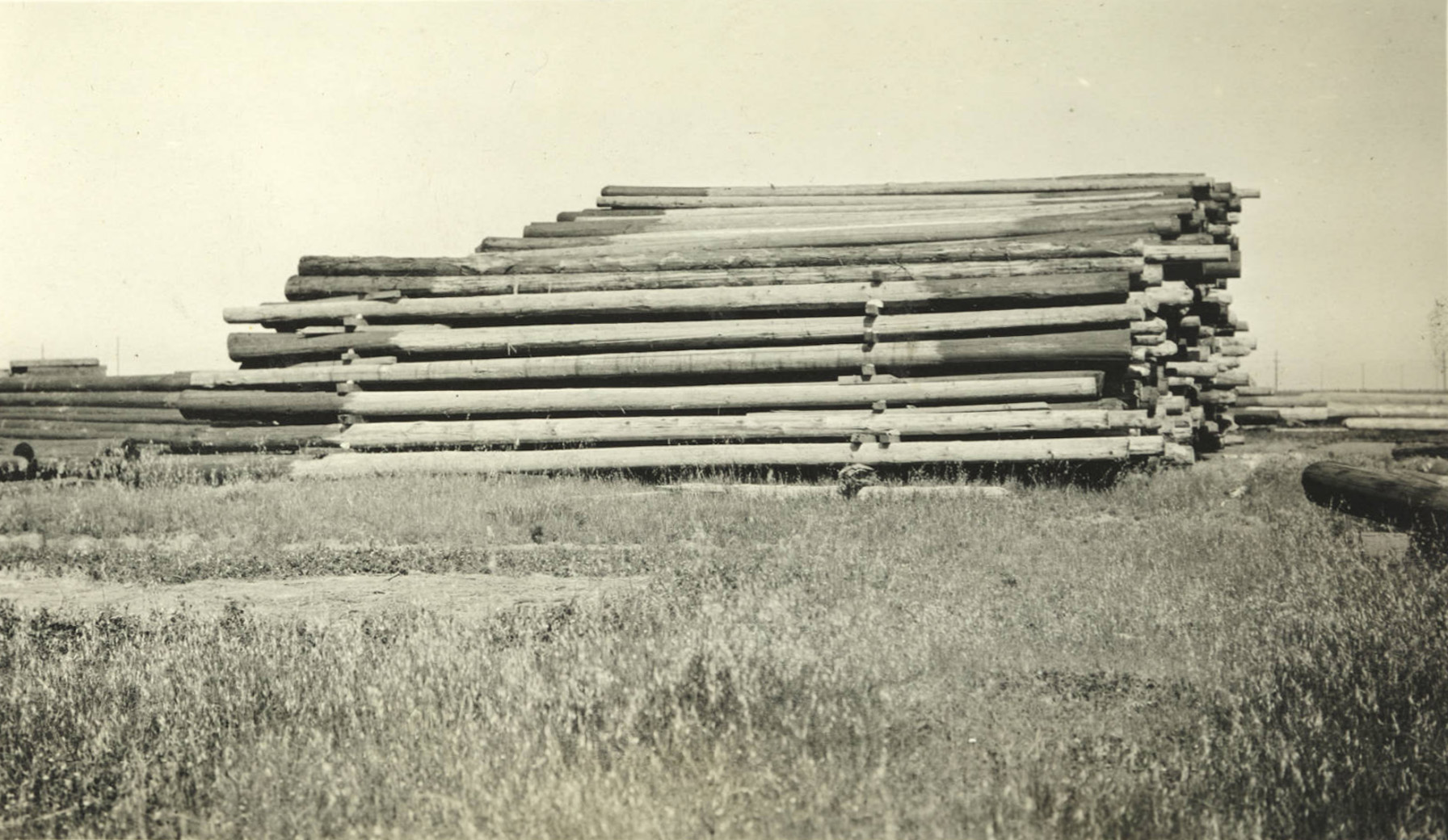 Wood transmission poles in the Mojave Desert "Pole Yard" |
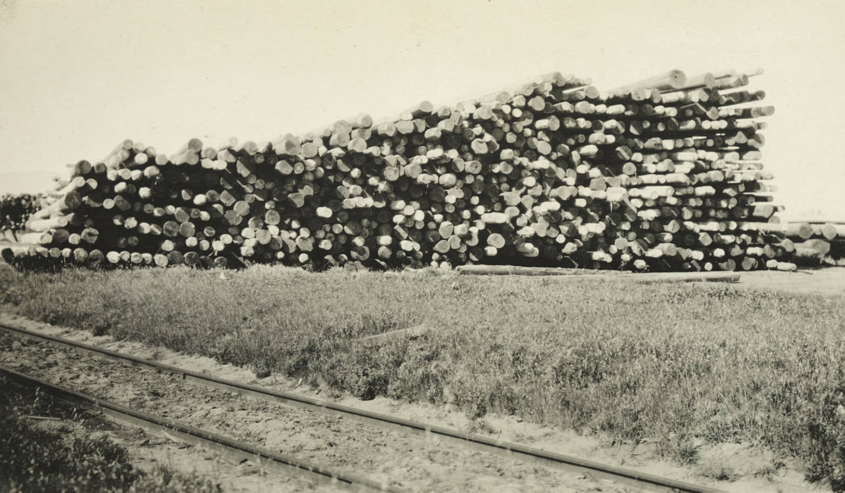 Wood transmission poles in the Mojave Desert "Pole Yard" |
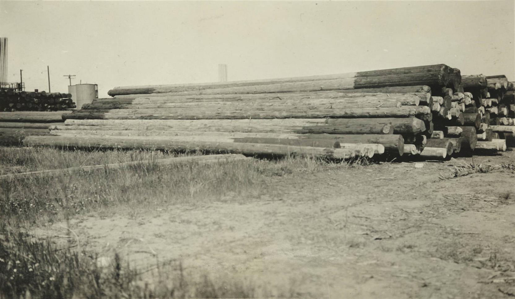 Wood transmission poles in the Mojave Desert "Pole Yard" |
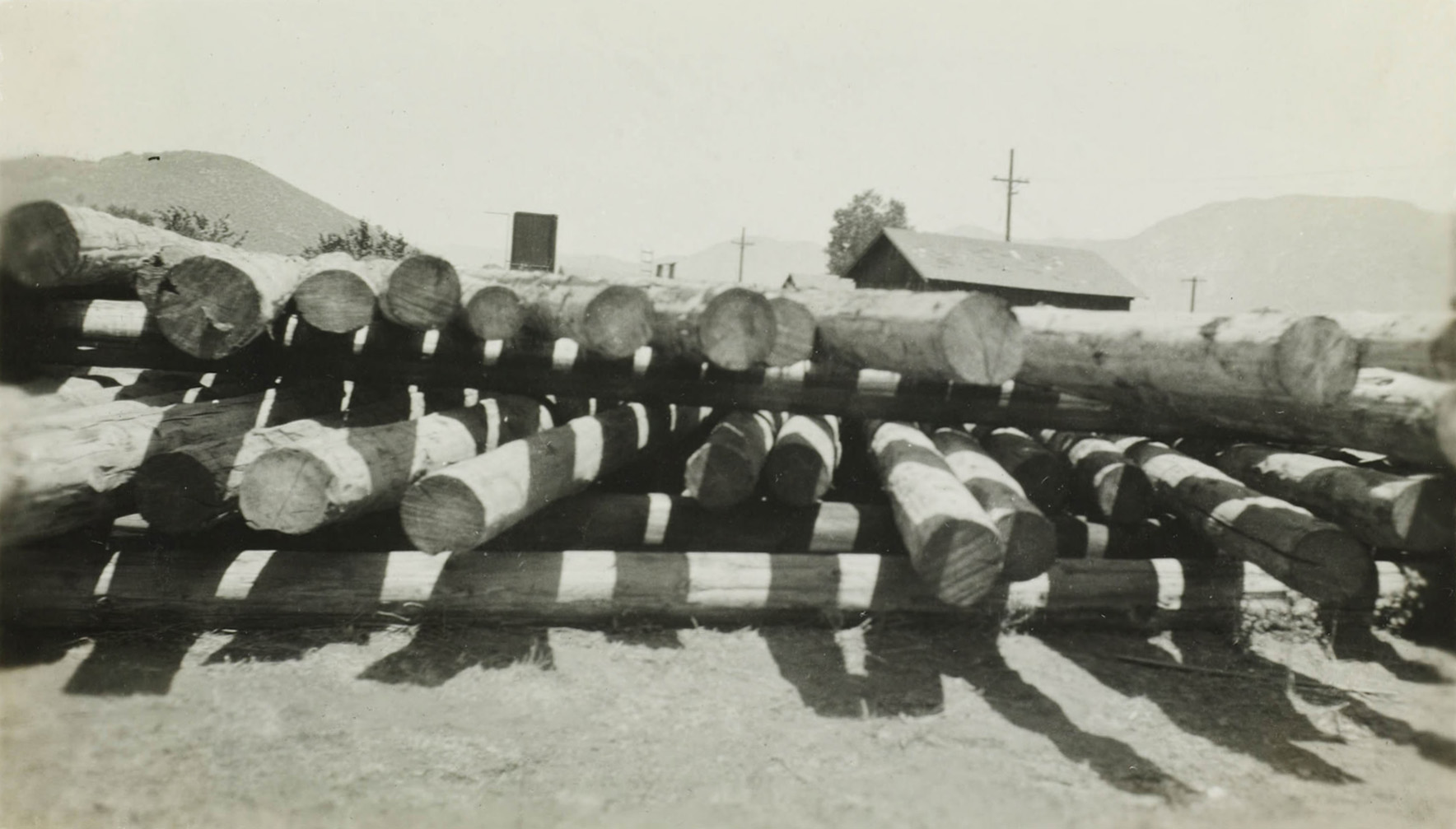 Wood transmission poles in the Mojave Desert "Pole Yard" |
 When the truck breaks down - revert to mule power |
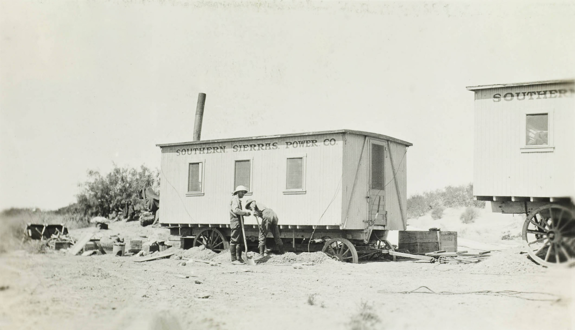 Crew quarters on the desert - stuck in the sand after a flash flood |
 Hauling transmission poles in the desert |
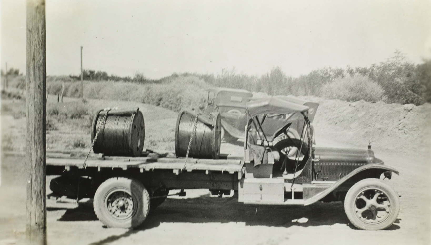 Coils of transmission wire |
 Erecting wood transmission towers in Owens Valley |
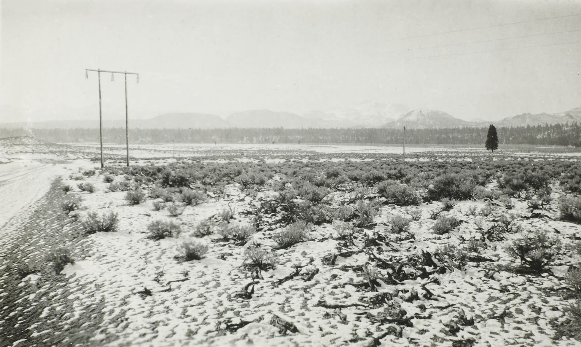 Silver Lake power lines in Owens Valley |
 Erecting wood transmission towers in Owens Valley |
|
 Erecting steel transmission towers in the Rose Valley |
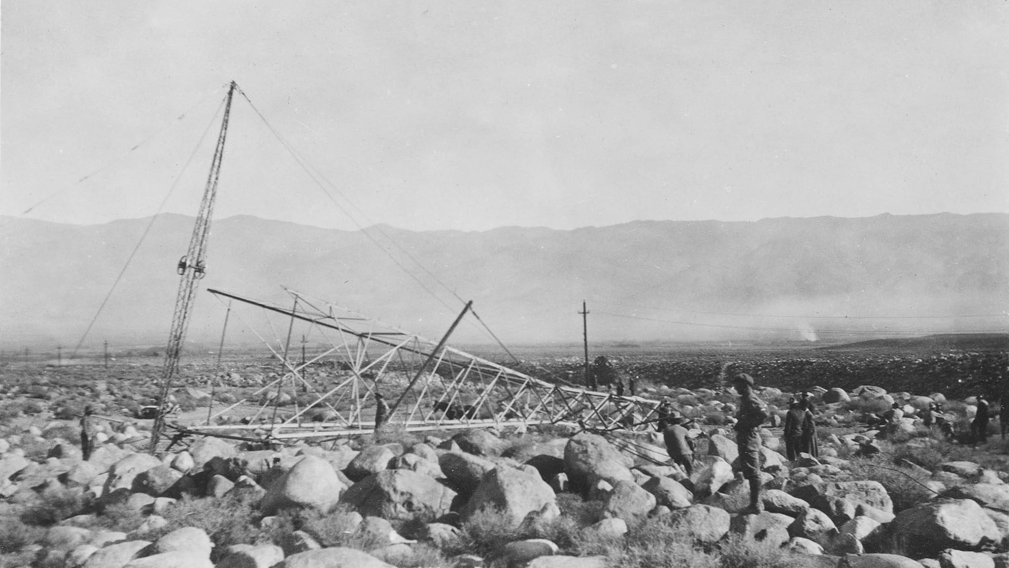 Erecting steel transmission towers in the Rose Valley |
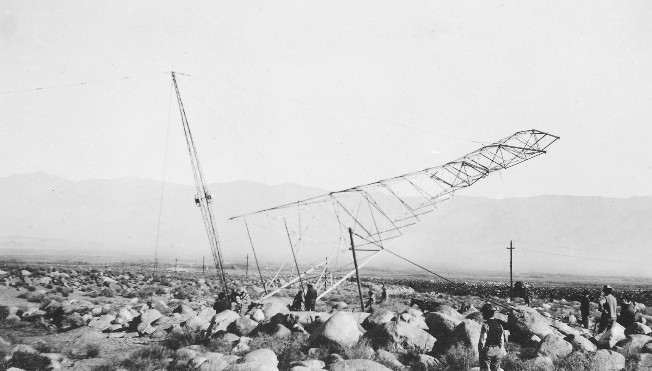 Erecting steel transmission towers in the Rose Valley |
 Erecting steel transmission towers in the Rose Valley |
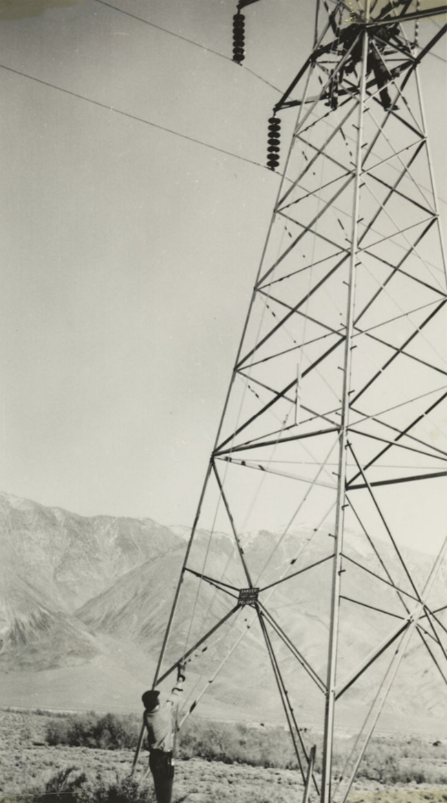
 Inspecting the transmission towers on the Mojave Desert |
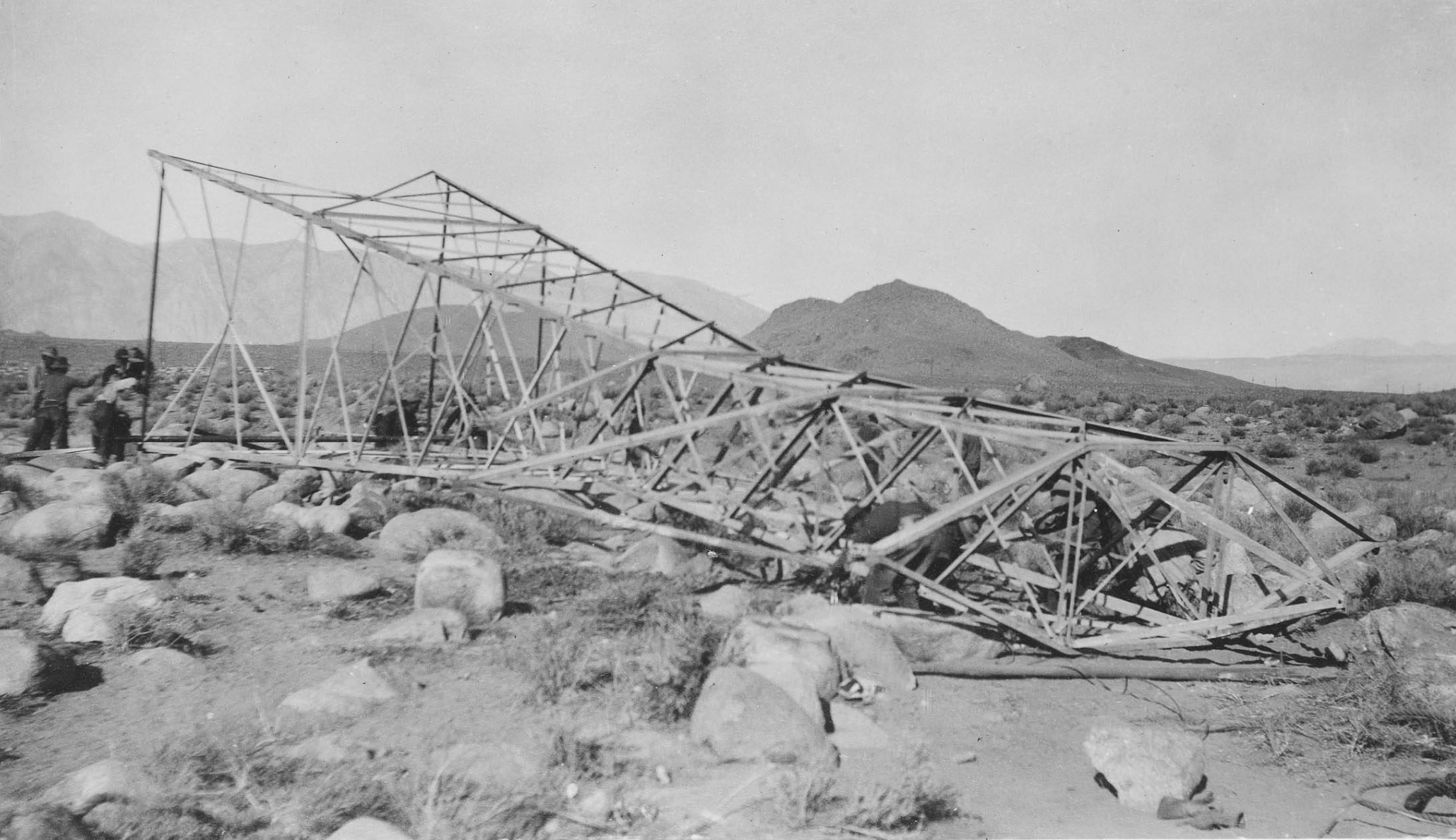
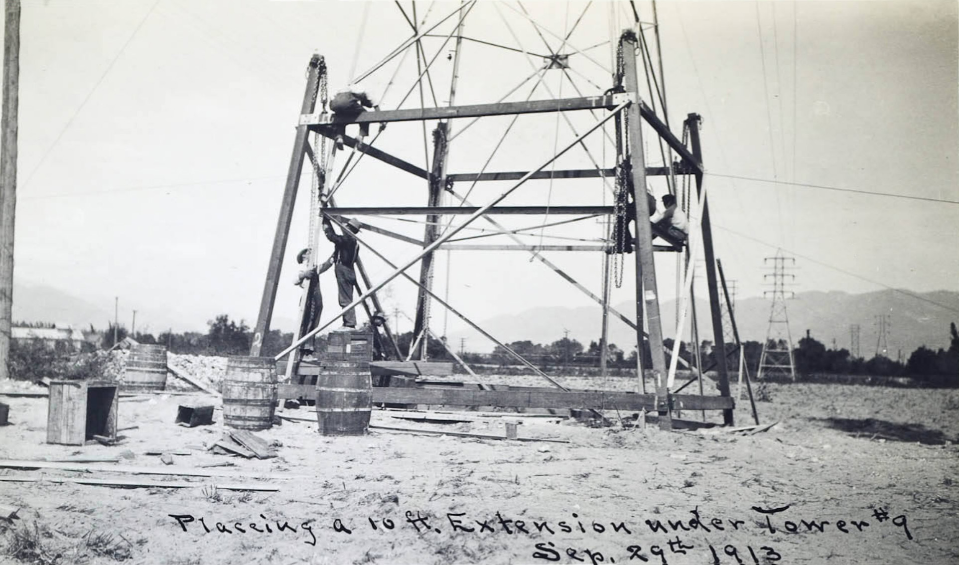 Making an extension to one of the steel transmission towers Note the block and tackle method of raising the extension. |
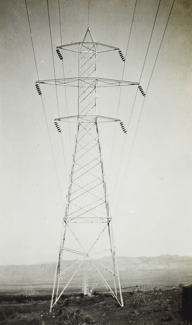 General view of tower in a windstorm showing strain on the insulators. |
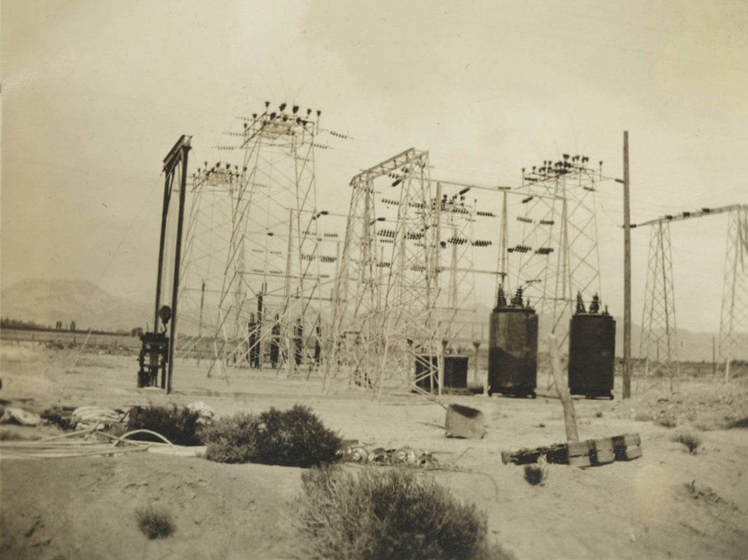 Lone Pine Sub-Station |
San Bernardino Power Distribution Center |
|
Main Substation of the Southern Sierras Power Company - San Bernardino, CA This is the southern terminus of the 238 mile steel tower transmission line from Control Station on Bishop Creek. Here current is received from four sources for distribution - from the eleven hydro plants in the North; from the San Bernardino steam-electric generating plant, shown on the right; from the interconnections with the Southern California Edison Company's system, and from the San Diego Consolidated Gas and Electric Company through the Rincon interconnection. Power is distributed here to all points on the System in Southern California and for resale in Arizona and Lower California. |
|
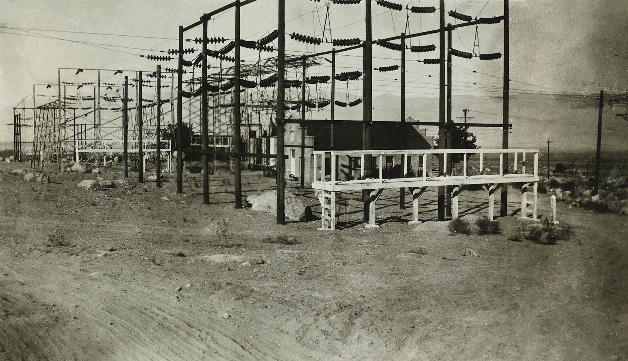
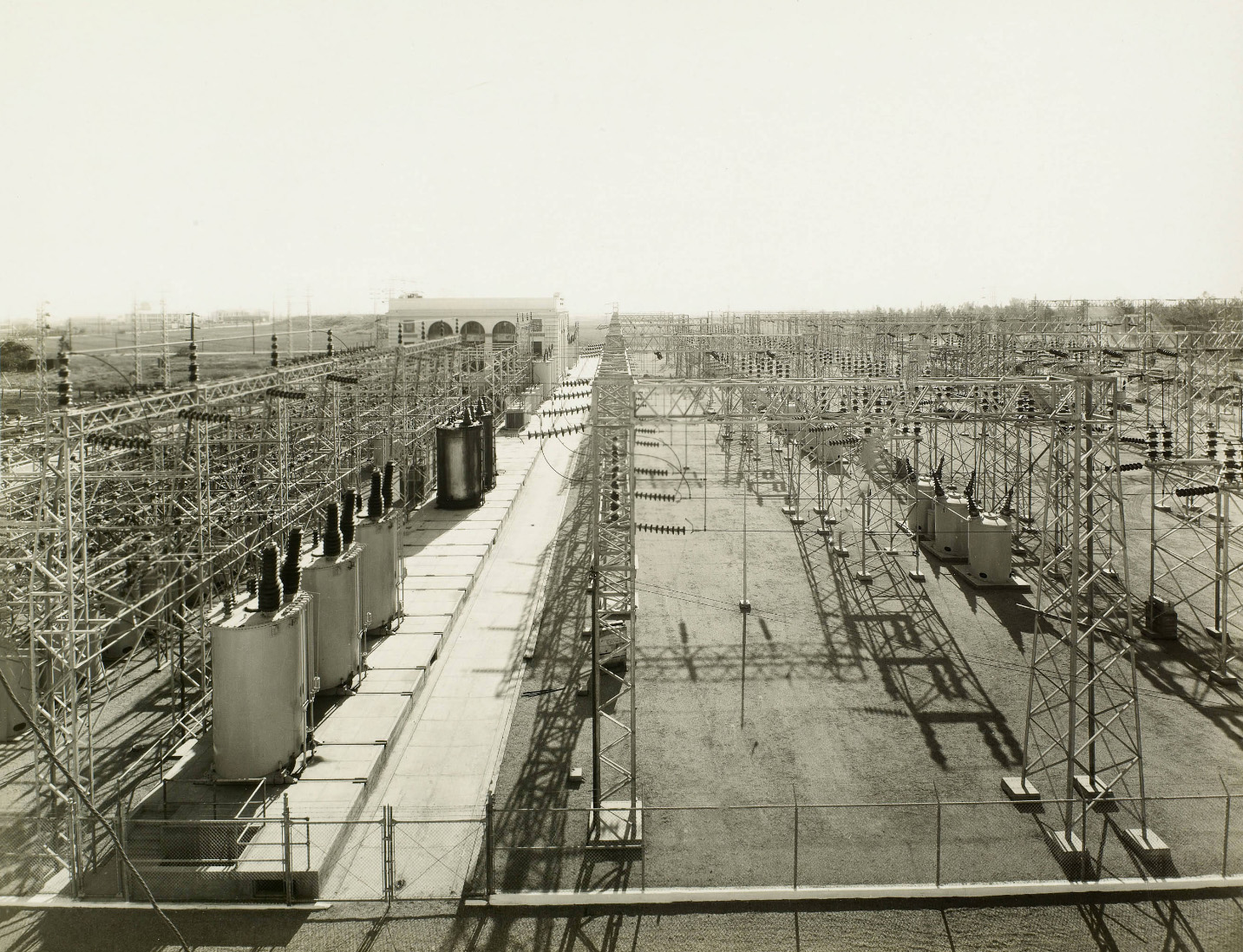 Main switching yard as seen from the steam plant in San Bernardino |
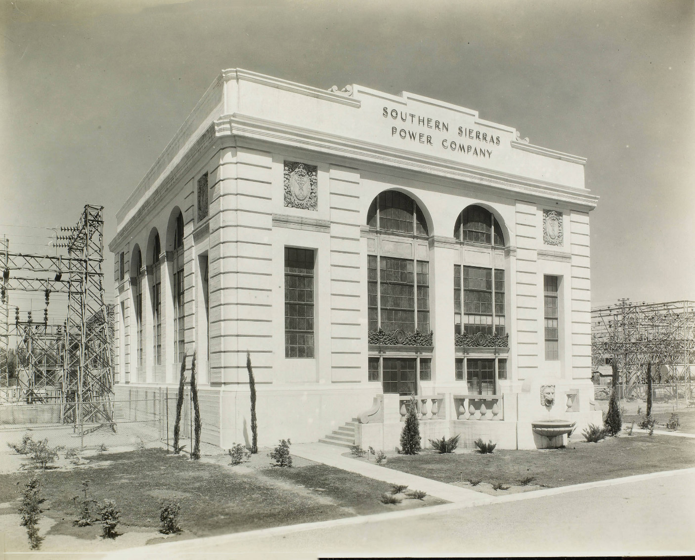 Southern Sierras Power Company headquarters in San Bernardino |
Big Pine Citizen Newspaper |
||
| A Thousand Acres of Nothing - 'Aim Morhardt and Lee Early | ||
| Irene Cuff | ||
More Eastern Sierra Nevada Power Plant Construction |
||
XXXXXXXXXX |
||
XXXXXXXXXX |
Sign Guestbook View Old Guest Book Entries Oct 1999 - Feb 2015 (MS Word) |
 CONTACT the Pigmy Packer |
View Guestbook View Old Guest Book Entries Oct 1999 - Feb 2015 (PDF) |